EP2631429B1 - Aubage - Google Patents
Aubage Download PDFInfo
- Publication number
- EP2631429B1 EP2631429B1 EP12157031.1A EP12157031A EP2631429B1 EP 2631429 B1 EP2631429 B1 EP 2631429B1 EP 12157031 A EP12157031 A EP 12157031A EP 2631429 B1 EP2631429 B1 EP 2631429B1
- Authority
- EP
- European Patent Office
- Prior art keywords
- blade
- side wall
- depression
- blades
- depressions
- Prior art date
- Legal status (The legal status is an assumption and is not a legal conclusion. Google has not performed a legal analysis and makes no representation as to the accuracy of the status listed.)
- Active
Links
Images


Classifications
-
- F—MECHANICAL ENGINEERING; LIGHTING; HEATING; WEAPONS; BLASTING
- F01—MACHINES OR ENGINES IN GENERAL; ENGINE PLANTS IN GENERAL; STEAM ENGINES
- F01D—NON-POSITIVE DISPLACEMENT MACHINES OR ENGINES, e.g. STEAM TURBINES
- F01D5/00—Blades; Blade-carrying members; Heating, heat-insulating, cooling or antivibration means on the blades or the members
- F01D5/12—Blades
- F01D5/14—Form or construction
- F01D5/141—Shape, i.e. outer, aerodynamic form
- F01D5/142—Shape, i.e. outer, aerodynamic form of the blades of successive rotor or stator blade-rows
- F01D5/143—Contour of the outer or inner working fluid flow path wall, i.e. shroud or hub contour
-
- F—MECHANICAL ENGINEERING; LIGHTING; HEATING; WEAPONS; BLASTING
- F04—POSITIVE - DISPLACEMENT MACHINES FOR LIQUIDS; PUMPS FOR LIQUIDS OR ELASTIC FLUIDS
- F04D—NON-POSITIVE-DISPLACEMENT PUMPS
- F04D29/00—Details, component parts, or accessories
- F04D29/40—Casings; Connections of working fluid
- F04D29/52—Casings; Connections of working fluid for axial pumps
- F04D29/54—Fluid-guiding means, e.g. diffusers
- F04D29/541—Specially adapted for elastic fluid pumps
- F04D29/542—Bladed diffusers
- F04D29/544—Blade shapes
-
- Y—GENERAL TAGGING OF NEW TECHNOLOGICAL DEVELOPMENTS; GENERAL TAGGING OF CROSS-SECTIONAL TECHNOLOGIES SPANNING OVER SEVERAL SECTIONS OF THE IPC; TECHNICAL SUBJECTS COVERED BY FORMER USPC CROSS-REFERENCE ART COLLECTIONS [XRACs] AND DIGESTS
- Y02—TECHNOLOGIES OR APPLICATIONS FOR MITIGATION OR ADAPTATION AGAINST CLIMATE CHANGE
- Y02T—CLIMATE CHANGE MITIGATION TECHNOLOGIES RELATED TO TRANSPORTATION
- Y02T50/00—Aeronautics or air transport
- Y02T50/60—Efficient propulsion technologies, e.g. for aircraft
Definitions
- the invention relates to a blading for a turbomachine, in particular a gas turbine, according to the preamble of claim 1 and a manufacturing method for such blading.
- a vane passage of a turbomachine is generally defined by a hub and a shell side sidewall, and vanes or blades therebetween, which sidewalls may each be hub or housing fixed.
- increased deflections of the flow in the region of the side walls can occur due to the influence of the wall friction, resulting in some strong secondary currents. These secondary flows cause increased losses.
- a blading for a turbine wherein on a side wall having a number of blades, suction and pressure side and downstream of the blade outlet edges and depressions are formed in the middle between adjacent blades.
- suction and pressure side and downstream of the blade outlet edges and depressions are formed in the middle between adjacent blades.
- Blades for turbines or turbomachines are known in which on a number of blades having side wall elevations are formed.
- US 2007/258818 A1 discloses a blading having a plurality of blades disposed on a side wall.
- a first thickening is provided on a blade pressure side and a depression is provided on a blade suction side.
- a second thickening extends from the first thickening parallel to the vane pressure side and the vane suction side, and extends between the vane pressure side and the vane suction side.
- the second thickening is not connected to the blade suction side.
- EP 1 712 737 A1 discloses a blading with a thickening and a depression. The thickening and depression each extend over the entire blade length.
- the object of the present invention is to provide an improved blading and a method for the production thereof.
- a blading for a turbomachine in which protrusions and depressions are formed on a side wall having a plurality of blades, at least one depression on a blade pressure side and at least one depression on a blade suction side are respectively formed for the number of blades arranged.
- a blading for a turbomachine in which protrusions and depressions are formed on a side wall having a plurality of blades, at least one depression on a blade suction side and at least one expansion on a blade pressure side are respectively formed for the number of blades arranged.
- a further advantage of this embodiment may also be an increase in the operating range of the turbomachines.
- An advantage may also lie in a simple design implementation and / or the applicability for already existing designs of turbomachinery.
- blading is in particular an arrangement of moving blades and / or an arrangement of guide vanes, in particular one or more stages.
- a blading according to the invention is particularly suitable for high pressure compressors.
- an aircraft engine has a blading according to the invention.
- a side wall in the sense of the present invention may be hub- or rotor- and / or housing-side as well as hub or rotor and / or housing fixed.
- one side wall may be the hub side, i. radially inner and hub fixed circumferential surface of a play screen, and / or the housing side, i. radially outer circumferential surface of a play screen, which may be formed in particular by a hub-fixed shroud or a housing-fixed inner surface include.
- a side wall may comprise the housing-side, radially outer peripheral surface and / or the hub-side peripheral surface of a guide grid, which may be formed in particular by a cover band fixed to the housing or a hub-fixed outer surface.
- a recess or thickening in the sense of the present invention can, in particular with respect to a, in particular straight or curved, reference cone surface radially inward or outward projecting back or, which is concentric with a rotation axis.
- the reference cone surface may in particular pass through the radially innermost or radially outermost points of the side wall or therebetween.
- a radius of the reference cone surface may correspond to the mean value of the maximum and minimum or all radial extensions of the side wall.
- the indentation may also refer to a reference conical surface passing through an uncontoured region of the sidewall or a root or tip of the vanes.
- a larger radial dimension compared to the recess can be understood, under a depression corresponding to a smaller radial dimension compared to the thickening.
- the peaks or valleys represent depressions or depressions in the sense of the present invention with respect to the center line.
- the valleys mountains
- the valleys represent depressions (thickenings) relative to this reference cone surface
- the mountains valleys
- thickenings thickenings
- a depression (thickening) arranged on a blade suction or pressure side may be characterized in particular by a section in the circumferential direction which is perpendicular to an axis of rotation of the turbomachine (see, for example, L4 to L8 in FIG EP 1 995 410 A1 ), in particular such a section in the axial center of the blading (cf, for example, L6 in FIG EP 1 995 410 A1 ), the side wall on the blade root is lowered radially inwards (increased radially outward).
- the side wall in the axial direction before and / or after the pressure-side depressions and / or suction-side thickening uncontoured, ie has the same radius over the entire circumference of a radial section.
- the depression or thickening arranged on the blade pressure side and / or the thickening or depression arranged on the blade suction side, viewed in the flow direction, begins before, at or after the blade leading edge.
- the depression or thickening arranged on the blade pressure side and / or the thickening or depression arranged in the region of the blade suction side extend in the axial direction over at least 10%, preferably at least 30%, in particular at least 50% and preferably at least 60% of the axial Grid length, and / or at most 100%, in particular at most 80% of the axial grid length, measured in each case between the blade inlet and - outlet edge.
- the thickening or depression arranged on the blade suction side and / or the depression or thickening arranged on the blade pressure side is arranged entirely or partially in the axial half of the blade grid facing the inlet side during the blading.
- a radial extremum of the depressions and / or thickening which is arranged on a blade pressure or suction side, in the axial direction at least 10%, in particular at least 20%, preferably at least 40% and / or at most 90%, in particular at most 80%, preferably at most 60% of the blade chord length away from the blade leading edge.
- a radial minimum of the recesses may be in a range that extends between 20% and 60% of the blade chord length measured from the blade leading edge.
- a radial maximum of the thickening may in particular lie in a range which extends between 40% and 80% of the blade chord length, measured from the blade leading edge.
- a further thickening is arranged in the side facing the outlet side.
- This further thickening can be arranged and designed to be circumferentially symmetrical.
- this further thickening can be arranged circumferentially asymmetrically and configured.
- the ratio of the extent of this further thickening in the circumferential direction to its extent in the axial or flow direction can be less than 1, ie, this further thickening in the axial or flow direction can be "stretched".
- the further thickening arranged in the half facing the outlet side may preferably extend in the circumferential direction, at least substantially, from one to the adjacent blade.
- the second thickening may extend over at least 10% of the axial grid length. This further thickening may be radially higher or lower than the thickening arranged on a blade suction or pressure side.
- the depression located on a vane suction or pressure side extends on both sides of this further thickening, i. this further thickening may be arranged in the depression arranged on a blade suction or pressure side. Such further thickening then shares a fluid flow in the depression located on a blade suction or pressure side.
- a further symmetrically or circumferentially asymmetrically further thickening may be arranged at the leading edge of a blade, in particular a recess arranged in the direction of flow at a blade suction or pressure side.
- a fluid flow can be directed away from the blade root into the depression arranged on a blade suction or pressure side.
- the present invention can be applied to vane grids having a kinked, in particular at least substantially orthogonal, transition from the vane pressure and / or suction sides to the sidewall, as well as vane grids having a foot fillet surface in the transition region of the vane pressure and / or or suction sides to the side wall.
- a turbo-machine blading manufacturing method at least one master forming, forming, and / or machining is performed so as to form protrusions and depressions in a side wall having a plurality of blades, wherein the number of blades is formed in each case at least one depression or thickening on a blade pressure side and at least one thickening or depression on a blade suction side.
- the inventive design advantageously a blading with high efficiency, especially in a high-speed high-speed compressor (level) are provided.
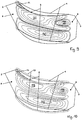
- the Fig. 1 shows a perspective view of a blading for a turbomachine with a contouring of the hub-side side wall 1 in a compressor stator grid in the hub region, wherein the housing wall in the Fig. 1 not shown.
- a number of blades 20 with a blade leading edge 2, a blade trailing edge 3, a blade pressure side 4 and a blade suction side 5 are arranged on a side wall 1, wherein the side wall 1 may preferably have an uncontoured region 8 at the grate entry and an uncontoured region 9 at the grate exit.
- the leading edge 6 on the blade root and the trailing edge 7 on the blade root are recognized.
- FIG. 12 is an illustration of the contouring of the side wall 1 for an example of the blading of the first aspect in a contour line diagram in which the blades 20 do not have a foot fillet surface and the isolines of the extent of the sidewall contour in the direction orthogonal to the sidewall are shown.
- a thickening 10 is arranged at the blade pressure side 4 at the blade pressure side 4 at the blade pressure side 4 at the blade pressure side 4 at the blade pressure side 4 a recess 11 and on the Schaufelsaugseite 5 a thickening 10 is arranged.
- this thickening 10 may be formed by a survey.
- this thickening 10 may be formed by a depression which is less pronounced with respect to the recess 11.
- a further thickening 12 extending from the blade suction side 5 to the blade pressure side 4 is in the side facing the outlet side (right in FIG Fig. 2 ) arranged.
- FIG. 3 shows a representation of the contouring of the side wall 1 for a further example of the blading according to the first aspect in a contour line diagram, in which the blades 20 have a foot flattening surface 13 which is shown in FIG Fig. 3 is shown in dashed lines, and in which the isolines of the extension of the side wall contour are shown in the direction orthogonal to the side wall.
- the depression 11 and at the blade suction side 5 the thickening 10 as well as the second thickening 12 extending from the blade suction side 5 to the blade pressure side 4 are arranged in the side adjacent to the outlet side on the blade pressure side 4.
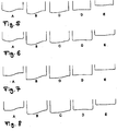
- sectional views along the blade channel lengths are shown below, wherein in the Fig. 4 the intersection positions are shown in the corresponding altitude line diagrams.
- Fig. 5 shows a representation of the blade walls and the hub-side side wall 1 of the sections A, B, C, D and E in the in the Fig. 4 shown cutting positions for a first embodiment of the blading, which has a non-orthogonal transition of the side wall 1 in the blades 20 and no favorausrundungs composition.
- Fig. 6 shows a representation of the blade walls and the hub-side side wall 1 of the sections A, B, C, D and E in the in the Fig. 4 shown cutting positions for a second embodiment of the blading, which has a non-orthogonal transition of the side wall 1 in the blades 20 and the dominantausrundungs component 13.
- Fig. 5 shows a representation of the blade walls and the hub-side side wall 1 of the sections A, B, C, D and E in the in the Fig. 4 shown cutting positions for a first embodiment of the blading, which has a non-orthogonal transition of the side wall 1 in the blades 20 and no instructaus
- FIG. 7 shows a representation of the blade walls and the hub-side side wall 1 of the sections A, B, C, D and E in the in the Fig. 4 shown sectional positions for a third embodiment of the blading, which has an orthogonal transition of the side wall 1 in the blades 20 and no favorausrundungs salt.
- Fig. 8 shows a representation of the blade walls and the hub-side side wall 1 of the sections A, B, C, D and E in the in the Fig. 4 shown cutting positions for a fourth embodiment of the blading, which has an orthogonal transition of the side wall 1 in the blades 20 and the dominantausrundungs component 13.
- the invention may also be applied to combinations of an orthogonal and a non-orthogonal transition in which an orthogonal transition occurs at the blade pressure side 4 or at the blade suction side 5, while at the other of the two blade walls delimiting the flow channel a non-orthogonal transition from the side wall 1 to the blade 20 takes place.
- Fig. 9 1 is a contour view of the side wall 1 for an exemplary embodiment of the blading according to the second aspect, in a contour line diagram in which the blades 20 do not have a foot flattening surface and in which the isolines of the extension of the side wall contour in the direction orthogonal to the side wall are shown.
- On the blade pressure side 4 is a thickening 10 and on the Schaufelsaugseite 5 is a recess 11 is arranged.
- this thickening 10 may be formed by a survey.
- this thickening 10 may be formed by a depression which is less pronounced with respect to the recess 11.
- a further thickening 12 in the recess 11 and a further thickening 14 at the leading edge 2 of the blades 20 is arranged.
- Fig. 10 shows a representation of the contouring of the side wall 1 for a further embodiment of the blading according to the second aspect in a contour line diagram in which the blades 20 have a predominantlyausrundungs constitutional 13, in the Fig. 10 is shown in dashed lines. Otherwise, the embodiment corresponds to Fig. 10 the above-described embodiment of the Fig. 9 ,
- Fig. 11 shows a representation of the contouring of the side wall 1 for a further example of the blading according to the second aspect in Fig. 9 corresponding representation, in which in the recess 11 no further thickening (see, further thickening 12 in Fig. 9 ) is provided.
- the example corresponds to the Fig. 11 the above-described embodiment of the Fig. 9 .
- Fig. 12 shows a representation of the contouring of the side wall 1 for a further example of the blading according to the second aspect in Fig. 10 corresponding representation, in which in the recess 11 no further thickening (see, further thickening 12 in Fig. 10 ) is provided.
- the example corresponds to the Fig. 12 the above-described embodiment of the Fig. 10 .
Landscapes
- Engineering & Computer Science (AREA)
- Physics & Mathematics (AREA)
- Fluid Mechanics (AREA)
- Mechanical Engineering (AREA)
- General Engineering & Computer Science (AREA)
- Geometry (AREA)
- Structures Of Non-Positive Displacement Pumps (AREA)
Claims (10)
- Aubage d'une turbomachine, dans lequel des renflements (10) et des évidements (11) sont formés sur une paroi latérale (1) pourvue d'une pluralité d'aubes (20) ; pour chaque aube de la pluralité d'aubes (20), au moins un évidement (11) est disposé sur un côté sous pression (4) et au moins un renflement (10) étant disposé sur un côté sous dépression (5) ; la paroi latérale (1) n'est pas profilée axialement après l'évidement (11) ; caractérisé en ce qu'un autre renflement (12) à symétrie périphérique ou asymétrie périphérique est disposé dans la moitié de grille d'aubes dirigée vers le côté sortie, entre le côté sous dépression et le côté sous pression, et l'évidement (11) s'étend des deux côtés de cet autre renflement (12) conformé en bosse.
- Aubage d'une turbomachine, dans lequel des renflements (10) et des évidements (11) sont formés sur une paroi latérale (1) pourvue d'une pluralité d'aubes (20) ; pour chaque aube de la pluralité d'aubes (20), au moins un évidement (11) est disposé sur un côté sous dépression (5) et au moins un renflement (10) est disposé sur un côté sous pression (4), et un autre renflement (12) à symétrie périphérique ou asymétrie périphérique est disposé dans la moitié de grille d'aubes dirigée vers le côté sortie, entre le côté sous dépression et le côté sous pression ; caractérisé en ce que l'évidement (11) s'étend des deux côtés de cet autre renflement (12) conformé en bosse et la paroi latérale (1) n'est pas profilée axialement après l'évidement (11).
- Aubage selon l'une des revendications précédentes, caractérisé en ce que la paroi latérale n'est pas profilée axialement avant et/ou après les renflements et/ou les évidements.
- Aubage selon l'une des revendications précédentes, caractérisé en ce que les évidements et/ou les renflements, qui sont disposés sur un côté sous pression ou dépression des aubes, sont au moins partiellement disposés dans la moitié de la grille d'aubes dirigée vers le côté entrée.
- Aubage selon l'une des revendications précédentes, caractérisé en ce que les évidements et/ou des les renflements, qui sont disposés sur un côté sous pression ou dépression, s'étendent dans la direction axiale sur au moins 10%, de préférence au moins 30%, en particulier au moins 50%, de façon préférée au moins 60%, de la longueur de la grille axiale.
- Aubage selon l'une des revendications précédentes, caractérisé en ce qu'un extremum des évidements et/ou des renflements, qui sont disposés sur un côté sous pression ou dépression, se trouve à une distance du bord d'attaque des aubes dans la direction axiale d'au moins 10%, en particulier d'au moins 20%, de préférence d'au moins 40% et/ou d'au plus 90%, notamment d'au plus 80%, de préférence d'au plus 60% de la longueur de corde de l'aube.
- Aubage selon l'une des revendications précédentes, caractérisé en outre par un autre renflement (14) à symétrie périphérique ou asymétrie périphérique au niveau du bord d'attaque des aubes, notamment du côté sous pression et/ou dépression de l'aube.
- Aubage selon l'une des revendications précédentes, caractérisé en ce qu'au niveau de la transition entre l'aube (20) et la paroi latérale (1), l'aube (20) présente une aire de congé d'embase (13).
- Aubage selon l'une des revendications précédentes, caractérisé en ce qu'au niveau de la transition entre l'aube (20) et la paroi latérale (1), l'aube (20) présente une transition flambée, en particulier orthogonale.
- Procédé de fabrication d'un aubage selon l'une des revendications précédentes, comprenant au moins une étape de formage et/ou au moins une étape d'usinage à enlèvement de copeaux, de telle sorte que des renflements (10) et des évidements (11) sont formés au niveau de la paroi latérale (1) pourvue d'une pluralité d'aubes (20) ; pour chaque aube de la pluralité d'aubes, au moins un évidement (11) ou renflement (10) est formé du côté sous pression (4), au moins un renflement (10) ou évidement (11) est formé du côté sous dépression (5) et un autre renflement (12) à symétrie périphérique ou à asymétrie périphérique est formé dans la moitié de grille d'aubes, dirigée vers le côté sortie, entre le côté sous dépression et le côté sous pression, la paroi latérale (1) n'étant pas profilée axialement après l'autre renflement (12) conformé en bosse et l'évidement (11) s'étendant des deux côtés de cet autre renflement (12).
Priority Applications (4)
| Application Number | Priority Date | Filing Date | Title |
|---|---|---|---|
| ES12157031.1T ES2573118T3 (es) | 2012-02-27 | 2012-02-27 | Álabes |
| EP12157031.1A EP2631429B1 (fr) | 2012-02-27 | 2012-02-27 | Aubage |
| US13/683,669 US9194235B2 (en) | 2011-11-25 | 2012-11-21 | Blading |
| US14/933,581 US9963973B2 (en) | 2011-11-25 | 2015-11-05 | Blading |
Applications Claiming Priority (1)
| Application Number | Priority Date | Filing Date | Title |
|---|---|---|---|
| EP12157031.1A EP2631429B1 (fr) | 2012-02-27 | 2012-02-27 | Aubage |
Publications (2)
| Publication Number | Publication Date |
|---|---|
| EP2631429A1 EP2631429A1 (fr) | 2013-08-28 |
| EP2631429B1 true EP2631429B1 (fr) | 2016-05-11 |
Family
ID=45771684
Family Applications (1)
| Application Number | Title | Priority Date | Filing Date |
|---|---|---|---|
| EP12157031.1A Active EP2631429B1 (fr) | 2011-11-25 | 2012-02-27 | Aubage |
Country Status (2)
| Country | Link |
|---|---|
| EP (1) | EP2631429B1 (fr) |
| ES (1) | ES2573118T3 (fr) |
Cited By (1)
| Publication number | Priority date | Publication date | Assignee | Title |
|---|---|---|---|---|
| DE102023126341A1 (de) | 2023-09-27 | 2025-03-27 | MTU Aero Engines AG | Beschaufelung für eine Turbomaschine, sowie Turbomaschine |
Families Citing this family (2)
| Publication number | Priority date | Publication date | Assignee | Title |
|---|---|---|---|---|
| EP3401504B1 (fr) * | 2017-05-10 | 2024-07-03 | MTU Aero Engines AG | Grille d'aube |
| BE1026276B1 (fr) * | 2018-05-14 | 2019-12-17 | Safran Aero Boosters Sa | Bosse inter-aubes de compresseur de turbomachine axiale |
Citations (3)
| Publication number | Priority date | Publication date | Assignee | Title |
|---|---|---|---|---|
| EP2458148A1 (fr) * | 2010-11-25 | 2012-05-30 | Siemens Aktiengesellschaft | Composant de turbomachine avec surface de refroidissement |
| EP2589752A2 (fr) * | 2011-11-01 | 2013-05-08 | United Technologies Corporation | Contour d'extrémité d'aube de stator non axisymétrique |
| EP2597257A1 (fr) * | 2011-11-25 | 2013-05-29 | MTU Aero Engines GmbH | Aubage |
Family Cites Families (11)
| Publication number | Priority date | Publication date | Assignee | Title |
|---|---|---|---|---|
| DE3202855C1 (de) | 1982-01-29 | 1983-03-31 | MTU Motoren- und Turbinen-Union München GmbH, 8000 München | Einrichtung zur Verminderung von Sekundaerstroemungsverlusten in einem beschaufelten Stroemungskanal |
| GB9823840D0 (en) * | 1998-10-30 | 1998-12-23 | Rolls Royce Plc | Bladed ducting for turbomachinery |
| US7220100B2 (en) * | 2005-04-14 | 2007-05-22 | General Electric Company | Crescentic ramp turbine stage |
| JP4616781B2 (ja) | 2006-03-16 | 2011-01-19 | 三菱重工業株式会社 | タービン翼列エンドウォール |
| US8511978B2 (en) * | 2006-05-02 | 2013-08-20 | United Technologies Corporation | Airfoil array with an endwall depression and components of the array |
| GB0704426D0 (en) * | 2007-03-08 | 2007-04-18 | Rolls Royce Plc | Aerofoil members for a turbomachine |
| FR2928174B1 (fr) * | 2008-02-28 | 2011-05-06 | Snecma | Aube avec plateforme non axisymetrique : creux et bosse sur extrados. |
| US8105037B2 (en) * | 2009-04-06 | 2012-01-31 | United Technologies Corporation | Endwall with leading-edge hump |
| EP2248966B1 (fr) | 2009-05-09 | 2017-04-19 | Roto Frank Ag | Serrure de porte dotée d'un élément de fermeture et entraînement d'élément de fermeture commutable |
| US8439643B2 (en) * | 2009-08-20 | 2013-05-14 | General Electric Company | Biformal platform turbine blade |
| FR2950942B1 (fr) * | 2009-10-02 | 2013-08-02 | Snecma | Rotor d'un compresseur de turbomachine a paroi d'extremite interne optimisee |
-
2012
- 2012-02-27 EP EP12157031.1A patent/EP2631429B1/fr active Active
- 2012-02-27 ES ES12157031.1T patent/ES2573118T3/es active Active
Patent Citations (3)
| Publication number | Priority date | Publication date | Assignee | Title |
|---|---|---|---|---|
| EP2458148A1 (fr) * | 2010-11-25 | 2012-05-30 | Siemens Aktiengesellschaft | Composant de turbomachine avec surface de refroidissement |
| EP2589752A2 (fr) * | 2011-11-01 | 2013-05-08 | United Technologies Corporation | Contour d'extrémité d'aube de stator non axisymétrique |
| EP2597257A1 (fr) * | 2011-11-25 | 2013-05-29 | MTU Aero Engines GmbH | Aubage |
Cited By (3)
| Publication number | Priority date | Publication date | Assignee | Title |
|---|---|---|---|---|
| DE102023126341A1 (de) | 2023-09-27 | 2025-03-27 | MTU Aero Engines AG | Beschaufelung für eine Turbomaschine, sowie Turbomaschine |
| EP4534798A1 (fr) | 2023-09-27 | 2025-04-09 | MTU Aero Engines AG | Aubage pour turbomachine et turbomachine |
| US12460548B2 (en) | 2023-09-27 | 2025-11-04 | MTU Aero Engines AG | Blading assembly for a turbomachine and turbomachine |
Also Published As
| Publication number | Publication date |
|---|---|
| EP2631429A1 (fr) | 2013-08-28 |
| ES2573118T3 (es) | 2016-06-06 |
Similar Documents
| Publication | Publication Date | Title |
|---|---|---|
| DE69601283T2 (de) | Strömungsleitenden Vorrichtung für ein Gasturbinentriebwerk | |
| EP2242931B1 (fr) | Structure d'écoulement pour turbocompresseur | |
| EP2696029B1 (fr) | Grille d'aube avec définition de contour de la paroi latérale et turbomachine | |
| EP2787171B1 (fr) | Grille d'aubes avec définition de contour de la paroi latérale et turbomachine | |
| EP2746533B1 (fr) | Grille d'aube et turbomachine | |
| DE102004055439A1 (de) | Strömungsarbeitsmaschine mit dynamischer Strömungsbeeinflussung | |
| EP2597257B1 (fr) | Aubage | |
| DE102015101156A1 (de) | Laufschaufel mit hoher Sehnenlänge, zwei Teilspannweiten-Dämpferelementen und gekrümmtem Schwalbenschwanz | |
| CH710476A2 (de) | Verdichter mit einer Axialverdichterendwandeinrichtung zur Steuerung der Leckageströmung in dieser. | |
| EP1621733A2 (fr) | Dispositif d'écoulement pour turbine à gaz | |
| EP3404210A1 (fr) | Segment de grille d'aubes d'une turbomachine avec paroi de plateforme non-axisymétrique , grille d'aubes, canal d'aube, plateforme, turbomachine associés | |
| EP2806103B1 (fr) | Grille d'aubes et turbomachine | |
| DE102014203604A1 (de) | Schaufelreihengruppe | |
| CH701927B1 (de) | Statoranordnung, Kompressor und Gasturbinenmotor. | |
| EP2647796A1 (fr) | Système d'étanchéité pour turbomachine | |
| EP2631429B1 (fr) | Aubage | |
| EP2458149B1 (fr) | Aubage pour turboréacteur | |
| WO2005116404A1 (fr) | Aube comportant une zone de transition | |
| EP3388626B1 (fr) | Contournage d'une plate-forme de grille d'aube | |
| EP3650709A1 (fr) | Dispositif diffuseur à aubes pour un compresseur radial | |
| EP2871368A1 (fr) | Compresseur de turbine à gaz | |
| EP1723339A1 (fr) | Compresseur d'une turbine a gaz ainsi que turbine a gaz | |
| EP3492701A1 (fr) | Canal d'écoulement de turbomachine | |
| DE102013224199A1 (de) | Gasturbinen-Laufschaufel | |
| DE102013213416A1 (de) | Schaufel für eine Gasturbomaschine |
Legal Events
| Date | Code | Title | Description |
|---|---|---|---|
| PUAI | Public reference made under article 153(3) epc to a published international application that has entered the european phase |
Free format text: ORIGINAL CODE: 0009012 |
|
| 17P | Request for examination filed |
Effective date: 20121017 |
|
| AK | Designated contracting states |
Kind code of ref document: A1 Designated state(s): AL AT BE BG CH CY CZ DE DK EE ES FI FR GB GR HR HU IE IS IT LI LT LU LV MC MK MT NL NO PL PT RO RS SE SI SK SM TR |
|
| AX | Request for extension of the european patent |
Extension state: BA ME |
|
| RAP1 | Party data changed (applicant data changed or rights of an application transferred) |
Owner name: MTU AERO ENGINES AG |
|
| 17Q | First examination report despatched |
Effective date: 20140214 |
|
| REG | Reference to a national code |
Ref country code: DE Ref legal event code: R079 Ref document number: 502012007043 Country of ref document: DE Free format text: PREVIOUS MAIN CLASS: F01D0005140000 Ipc: F04D0029540000 |
|
| GRAP | Despatch of communication of intention to grant a patent |
Free format text: ORIGINAL CODE: EPIDOSNIGR1 |
|
| INTG | Intention to grant announced |
Effective date: 20160212 |
|
| RIC1 | Information provided on ipc code assigned before grant |
Ipc: F04D 29/54 20060101AFI20160201BHEP Ipc: F01D 5/14 20060101ALI20160201BHEP Ipc: F04D 29/68 20060101ALI20160201BHEP |
|
| GRAS | Grant fee paid |
Free format text: ORIGINAL CODE: EPIDOSNIGR3 |
|
| GRAA | (expected) grant |
Free format text: ORIGINAL CODE: 0009210 |
|
| AK | Designated contracting states |
Kind code of ref document: B1 Designated state(s): AL AT BE BG CH CY CZ DE DK EE ES FI FR GB GR HR HU IE IS IT LI LT LU LV MC MK MT NL NO PL PT RO RS SE SI SK SM TR |
|
| REG | Reference to a national code |
Ref country code: GB Ref legal event code: FG4D Free format text: NOT ENGLISH |
|
| REG | Reference to a national code |
Ref country code: CH Ref legal event code: EP |
|
| REG | Reference to a national code |
Ref country code: AT Ref legal event code: REF Ref document number: 798897 Country of ref document: AT Kind code of ref document: T Effective date: 20160515 |
|
| REG | Reference to a national code |
Ref country code: IE Ref legal event code: FG4D Free format text: LANGUAGE OF EP DOCUMENT: GERMAN |
|
| REG | Reference to a national code |
Ref country code: ES Ref legal event code: FG2A Ref document number: 2573118 Country of ref document: ES Kind code of ref document: T3 Effective date: 20160606 |
|
| REG | Reference to a national code |
Ref country code: DE Ref legal event code: R096 Ref document number: 502012007043 Country of ref document: DE |
|
| REG | Reference to a national code |
Ref country code: LT Ref legal event code: MG4D |
|
| REG | Reference to a national code |
Ref country code: NL Ref legal event code: MP Effective date: 20160511 |
|
| PG25 | Lapsed in a contracting state [announced via postgrant information from national office to epo] |
Ref country code: NL Free format text: LAPSE BECAUSE OF FAILURE TO SUBMIT A TRANSLATION OF THE DESCRIPTION OR TO PAY THE FEE WITHIN THE PRESCRIBED TIME-LIMIT Effective date: 20160511 Ref country code: NO Free format text: LAPSE BECAUSE OF FAILURE TO SUBMIT A TRANSLATION OF THE DESCRIPTION OR TO PAY THE FEE WITHIN THE PRESCRIBED TIME-LIMIT Effective date: 20160811 Ref country code: FI Free format text: LAPSE BECAUSE OF FAILURE TO SUBMIT A TRANSLATION OF THE DESCRIPTION OR TO PAY THE FEE WITHIN THE PRESCRIBED TIME-LIMIT Effective date: 20160511 Ref country code: LT Free format text: LAPSE BECAUSE OF FAILURE TO SUBMIT A TRANSLATION OF THE DESCRIPTION OR TO PAY THE FEE WITHIN THE PRESCRIBED TIME-LIMIT Effective date: 20160511 |
|
| PG25 | Lapsed in a contracting state [announced via postgrant information from national office to epo] |
Ref country code: RS Free format text: LAPSE BECAUSE OF FAILURE TO SUBMIT A TRANSLATION OF THE DESCRIPTION OR TO PAY THE FEE WITHIN THE PRESCRIBED TIME-LIMIT Effective date: 20160511 Ref country code: LV Free format text: LAPSE BECAUSE OF FAILURE TO SUBMIT A TRANSLATION OF THE DESCRIPTION OR TO PAY THE FEE WITHIN THE PRESCRIBED TIME-LIMIT Effective date: 20160511 Ref country code: HR Free format text: LAPSE BECAUSE OF FAILURE TO SUBMIT A TRANSLATION OF THE DESCRIPTION OR TO PAY THE FEE WITHIN THE PRESCRIBED TIME-LIMIT Effective date: 20160511 Ref country code: GR Free format text: LAPSE BECAUSE OF FAILURE TO SUBMIT A TRANSLATION OF THE DESCRIPTION OR TO PAY THE FEE WITHIN THE PRESCRIBED TIME-LIMIT Effective date: 20160812 Ref country code: SE Free format text: LAPSE BECAUSE OF FAILURE TO SUBMIT A TRANSLATION OF THE DESCRIPTION OR TO PAY THE FEE WITHIN THE PRESCRIBED TIME-LIMIT Effective date: 20160511 Ref country code: PT Free format text: LAPSE BECAUSE OF FAILURE TO SUBMIT A TRANSLATION OF THE DESCRIPTION OR TO PAY THE FEE WITHIN THE PRESCRIBED TIME-LIMIT Effective date: 20160912 |
|
| PG25 | Lapsed in a contracting state [announced via postgrant information from national office to epo] |
Ref country code: IT Free format text: LAPSE BECAUSE OF FAILURE TO SUBMIT A TRANSLATION OF THE DESCRIPTION OR TO PAY THE FEE WITHIN THE PRESCRIBED TIME-LIMIT Effective date: 20160511 |
|
| PG25 | Lapsed in a contracting state [announced via postgrant information from national office to epo] |
Ref country code: DK Free format text: LAPSE BECAUSE OF FAILURE TO SUBMIT A TRANSLATION OF THE DESCRIPTION OR TO PAY THE FEE WITHIN THE PRESCRIBED TIME-LIMIT Effective date: 20160511 Ref country code: SK Free format text: LAPSE BECAUSE OF FAILURE TO SUBMIT A TRANSLATION OF THE DESCRIPTION OR TO PAY THE FEE WITHIN THE PRESCRIBED TIME-LIMIT Effective date: 20160511 Ref country code: RO Free format text: LAPSE BECAUSE OF FAILURE TO SUBMIT A TRANSLATION OF THE DESCRIPTION OR TO PAY THE FEE WITHIN THE PRESCRIBED TIME-LIMIT Effective date: 20160511 Ref country code: EE Free format text: LAPSE BECAUSE OF FAILURE TO SUBMIT A TRANSLATION OF THE DESCRIPTION OR TO PAY THE FEE WITHIN THE PRESCRIBED TIME-LIMIT Effective date: 20160511 Ref country code: CZ Free format text: LAPSE BECAUSE OF FAILURE TO SUBMIT A TRANSLATION OF THE DESCRIPTION OR TO PAY THE FEE WITHIN THE PRESCRIBED TIME-LIMIT Effective date: 20160511 |
|
| REG | Reference to a national code |
Ref country code: DE Ref legal event code: R097 Ref document number: 502012007043 Country of ref document: DE |
|
| REG | Reference to a national code |
Ref country code: FR Ref legal event code: PLFP Year of fee payment: 6 |
|
| PG25 | Lapsed in a contracting state [announced via postgrant information from national office to epo] |
Ref country code: SM Free format text: LAPSE BECAUSE OF FAILURE TO SUBMIT A TRANSLATION OF THE DESCRIPTION OR TO PAY THE FEE WITHIN THE PRESCRIBED TIME-LIMIT Effective date: 20160511 Ref country code: PL Free format text: LAPSE BECAUSE OF FAILURE TO SUBMIT A TRANSLATION OF THE DESCRIPTION OR TO PAY THE FEE WITHIN THE PRESCRIBED TIME-LIMIT Effective date: 20160511 |
|
| PLBE | No opposition filed within time limit |
Free format text: ORIGINAL CODE: 0009261 |
|
| STAA | Information on the status of an ep patent application or granted ep patent |
Free format text: STATUS: NO OPPOSITION FILED WITHIN TIME LIMIT |
|
| 26N | No opposition filed |
Effective date: 20170214 |
|
| PG25 | Lapsed in a contracting state [announced via postgrant information from national office to epo] |
Ref country code: SI Free format text: LAPSE BECAUSE OF FAILURE TO SUBMIT A TRANSLATION OF THE DESCRIPTION OR TO PAY THE FEE WITHIN THE PRESCRIBED TIME-LIMIT Effective date: 20160511 Ref country code: BE Free format text: LAPSE BECAUSE OF NON-PAYMENT OF DUE FEES Effective date: 20170228 |
|
| PG25 | Lapsed in a contracting state [announced via postgrant information from national office to epo] |
Ref country code: MC Free format text: LAPSE BECAUSE OF FAILURE TO SUBMIT A TRANSLATION OF THE DESCRIPTION OR TO PAY THE FEE WITHIN THE PRESCRIBED TIME-LIMIT Effective date: 20160511 |
|
| REG | Reference to a national code |
Ref country code: CH Ref legal event code: PL |
|
| PG25 | Lapsed in a contracting state [announced via postgrant information from national office to epo] |
Ref country code: LI Free format text: LAPSE BECAUSE OF NON-PAYMENT OF DUE FEES Effective date: 20170228 Ref country code: CH Free format text: LAPSE BECAUSE OF NON-PAYMENT OF DUE FEES Effective date: 20170228 |
|
| REG | Reference to a national code |
Ref country code: IE Ref legal event code: MM4A |
|
| PG25 | Lapsed in a contracting state [announced via postgrant information from national office to epo] |
Ref country code: LU Free format text: LAPSE BECAUSE OF NON-PAYMENT OF DUE FEES Effective date: 20170227 |
|
| REG | Reference to a national code |
Ref country code: BE Ref legal event code: MM Effective date: 20170228 |
|
| REG | Reference to a national code |
Ref country code: FR Ref legal event code: PLFP Year of fee payment: 7 |
|
| PG25 | Lapsed in a contracting state [announced via postgrant information from national office to epo] |
Ref country code: IE Free format text: LAPSE BECAUSE OF NON-PAYMENT OF DUE FEES Effective date: 20170227 |
|
| REG | Reference to a national code |
Ref country code: AT Ref legal event code: MM01 Ref document number: 798897 Country of ref document: AT Kind code of ref document: T Effective date: 20170227 |
|
| PG25 | Lapsed in a contracting state [announced via postgrant information from national office to epo] |
Ref country code: AT Free format text: LAPSE BECAUSE OF NON-PAYMENT OF DUE FEES Effective date: 20170227 |
|
| PG25 | Lapsed in a contracting state [announced via postgrant information from national office to epo] |
Ref country code: MT Free format text: LAPSE BECAUSE OF FAILURE TO SUBMIT A TRANSLATION OF THE DESCRIPTION OR TO PAY THE FEE WITHIN THE PRESCRIBED TIME-LIMIT Effective date: 20160511 |
|
| PG25 | Lapsed in a contracting state [announced via postgrant information from national office to epo] |
Ref country code: AL Free format text: LAPSE BECAUSE OF FAILURE TO SUBMIT A TRANSLATION OF THE DESCRIPTION OR TO PAY THE FEE WITHIN THE PRESCRIBED TIME-LIMIT Effective date: 20160511 |
|
| PG25 | Lapsed in a contracting state [announced via postgrant information from national office to epo] |
Ref country code: HU Free format text: LAPSE BECAUSE OF FAILURE TO SUBMIT A TRANSLATION OF THE DESCRIPTION OR TO PAY THE FEE WITHIN THE PRESCRIBED TIME-LIMIT; INVALID AB INITIO Effective date: 20120227 |
|
| PG25 | Lapsed in a contracting state [announced via postgrant information from national office to epo] |
Ref country code: BG Free format text: LAPSE BECAUSE OF FAILURE TO SUBMIT A TRANSLATION OF THE DESCRIPTION OR TO PAY THE FEE WITHIN THE PRESCRIBED TIME-LIMIT Effective date: 20160511 |
|
| PG25 | Lapsed in a contracting state [announced via postgrant information from national office to epo] |
Ref country code: CY Free format text: LAPSE BECAUSE OF NON-PAYMENT OF DUE FEES Effective date: 20160511 |
|
| PG25 | Lapsed in a contracting state [announced via postgrant information from national office to epo] |
Ref country code: MK Free format text: LAPSE BECAUSE OF FAILURE TO SUBMIT A TRANSLATION OF THE DESCRIPTION OR TO PAY THE FEE WITHIN THE PRESCRIBED TIME-LIMIT Effective date: 20160511 |
|
| PG25 | Lapsed in a contracting state [announced via postgrant information from national office to epo] |
Ref country code: TR Free format text: LAPSE BECAUSE OF FAILURE TO SUBMIT A TRANSLATION OF THE DESCRIPTION OR TO PAY THE FEE WITHIN THE PRESCRIBED TIME-LIMIT Effective date: 20160511 |
|
| PG25 | Lapsed in a contracting state [announced via postgrant information from national office to epo] |
Ref country code: IS Free format text: LAPSE BECAUSE OF FAILURE TO SUBMIT A TRANSLATION OF THE DESCRIPTION OR TO PAY THE FEE WITHIN THE PRESCRIBED TIME-LIMIT Effective date: 20160911 |
|
| PGFP | Annual fee paid to national office [announced via postgrant information from national office to epo] |
Ref country code: GB Payment date: 20260219 Year of fee payment: 15 |
|
| PGFP | Annual fee paid to national office [announced via postgrant information from national office to epo] |
Ref country code: ES Payment date: 20260319 Year of fee payment: 15 |
|
| PGFP | Annual fee paid to national office [announced via postgrant information from national office to epo] |
Ref country code: DE Payment date: 20260217 Year of fee payment: 15 |
|
| PGFP | Annual fee paid to national office [announced via postgrant information from national office to epo] |
Ref country code: FR Payment date: 20260223 Year of fee payment: 15 |