EP2631504A1 - Boîtier d'expansion pour un frein à tambour - Google Patents
Boîtier d'expansion pour un frein à tambour Download PDFInfo
- Publication number
- EP2631504A1 EP2631504A1 EP13168710.5A EP13168710A EP2631504A1 EP 2631504 A1 EP2631504 A1 EP 2631504A1 EP 13168710 A EP13168710 A EP 13168710A EP 2631504 A1 EP2631504 A1 EP 2631504A1
- Authority
- EP
- European Patent Office
- Prior art keywords
- brake
- lever
- gear
- movement
- housing
- Prior art date
- Legal status (The legal status is an assumption and is not a legal conclusion. Google has not performed a legal analysis and makes no representation as to the accuracy of the status listed.)
- Withdrawn
Links
- 230000007246 mechanism Effects 0.000 claims description 9
- 238000000034 method Methods 0.000 abstract description 2
- 230000005540 biological transmission Effects 0.000 description 12
- 230000007480 spreading Effects 0.000 description 8
- 230000008878 coupling Effects 0.000 description 6
- 238000010168 coupling process Methods 0.000 description 6
- 238000005859 coupling reaction Methods 0.000 description 6
- 101100390736 Danio rerio fign gene Proteins 0.000 description 4
- 101100390738 Mus musculus Fign gene Proteins 0.000 description 4
- 230000008901 benefit Effects 0.000 description 4
- 230000005764 inhibitory process Effects 0.000 description 3
- 230000002427 irreversible effect Effects 0.000 description 3
- 230000008859 change Effects 0.000 description 2
- 239000000463 material Substances 0.000 description 2
- 230000004913 activation Effects 0.000 description 1
- 230000006978 adaptation Effects 0.000 description 1
- 230000001447 compensatory effect Effects 0.000 description 1
- 150000001875 compounds Chemical class 0.000 description 1
- 238000011109 contamination Methods 0.000 description 1
- 238000005553 drilling Methods 0.000 description 1
- 230000000694 effects Effects 0.000 description 1
- 230000003993 interaction Effects 0.000 description 1
- 230000000149 penetrating effect Effects 0.000 description 1
- 230000008569 process Effects 0.000 description 1
- 230000009467 reduction Effects 0.000 description 1
- 230000000630 rising effect Effects 0.000 description 1
Images


Classifications
-
- B—PERFORMING OPERATIONS; TRANSPORTING
- B60—VEHICLES IN GENERAL
- B60T—VEHICLE BRAKE CONTROL SYSTEMS OR PARTS THEREOF; BRAKE CONTROL SYSTEMS OR PARTS THEREOF, IN GENERAL; ARRANGEMENT OF BRAKING ELEMENTS ON VEHICLES IN GENERAL; PORTABLE DEVICES FOR PREVENTING UNWANTED MOVEMENT OF VEHICLES; VEHICLE MODIFICATIONS TO FACILITATE COOLING OF BRAKES
- B60T7/00—Brake-action initiating means
- B60T7/12—Brake-action initiating means for automatic initiation; for initiation not subject to will of driver or passenger
- B60T7/20—Brake-action initiating means for automatic initiation; for initiation not subject to will of driver or passenger specially for trailers, e.g. in case of uncoupling of or overrunning by trailer
- B60T7/203—Brake-action initiating means for automatic initiation; for initiation not subject to will of driver or passenger specially for trailers, e.g. in case of uncoupling of or overrunning by trailer with automatic brake release or reduction in case of reverse travel, e.g. by means of mechanisms mounted on the draw bar
- B60T7/206—Brake-action initiating means for automatic initiation; for initiation not subject to will of driver or passenger specially for trailers, e.g. in case of uncoupling of or overrunning by trailer with automatic brake release or reduction in case of reverse travel, e.g. by means of mechanisms mounted on the draw bar by means of mechanisms mounted on trailer drum brakes
-
- F—MECHANICAL ENGINEERING; LIGHTING; HEATING; WEAPONS; BLASTING
- F16—ENGINEERING ELEMENTS AND UNITS; GENERAL MEASURES FOR PRODUCING AND MAINTAINING EFFECTIVE FUNCTIONING OF MACHINES OR INSTALLATIONS; THERMAL INSULATION IN GENERAL
- F16D—COUPLINGS FOR TRANSMITTING ROTATION; CLUTCHES; BRAKES
- F16D51/00—Brakes with outwardly-movable braking members co-operating with the inner surface of a drum or the like
- F16D51/16—Brakes with outwardly-movable braking members co-operating with the inner surface of a drum or the like shaped as brake-shoes pivoted on a fixed or nearly-fixed axis
- F16D51/18—Brakes with outwardly-movable braking members co-operating with the inner surface of a drum or the like shaped as brake-shoes pivoted on a fixed or nearly-fixed axis with two brake-shoes
- F16D51/20—Brakes with outwardly-movable braking members co-operating with the inner surface of a drum or the like shaped as brake-shoes pivoted on a fixed or nearly-fixed axis with two brake-shoes extending in opposite directions from their pivots
-
- F—MECHANICAL ENGINEERING; LIGHTING; HEATING; WEAPONS; BLASTING
- F16—ENGINEERING ELEMENTS AND UNITS; GENERAL MEASURES FOR PRODUCING AND MAINTAINING EFFECTIVE FUNCTIONING OF MACHINES OR INSTALLATIONS; THERMAL INSULATION IN GENERAL
- F16D—COUPLINGS FOR TRANSMITTING ROTATION; CLUTCHES; BRAKES
- F16D65/00—Parts or details
- F16D65/38—Slack adjusters
- F16D65/40—Slack adjusters mechanical
- F16D65/52—Slack adjusters mechanical self-acting in one direction for adjusting excessive play
- F16D65/56—Slack adjusters mechanical self-acting in one direction for adjusting excessive play with screw-thread and nut
- F16D65/561—Slack adjusters mechanical self-acting in one direction for adjusting excessive play with screw-thread and nut for mounting within the confines of a drum brake
- F16D65/562—Slack adjusters mechanical self-acting in one direction for adjusting excessive play with screw-thread and nut for mounting within the confines of a drum brake arranged between service brake actuator and braking member, and subjected to service brake force
Definitions
- the invention relates to an expanding lock for a drum brake according to the preamble of patent claim 1.
- the known wheel brakes are, since they are intended primarily for trailer vehicles, equipped with a reverse automatic, which partially reverses the brake shoe support in a reverse drive of the trailer, and thus allows at least partial deflection of one or both brake shoes inwards. Even if the deflection takes place only at one end of the brake shoes, this still leads to a significantly increased Bremsbetutzutz, which would lead to an unwanted adjustment in a braking and without suitable compensatory measures. To avoid this, is at the EP 0 482 430 B1 the adjusting device connected to the evasive brake shoe arranged, this compound can be solved when reversing and thus at a cancellation of the brake shoe support.
- the adjusting device is provided with a release device in the form of a further lever mounted outside on the expansion housing. This triggers in the case of a greatly increased Bremsbetuschistshubs the engagement of the adjusting lever in the Nachstelltechnikrad.
- the invention has for its object to provide an improved expansion lock with adjusting device for a suitable for use with a reversing automatic wheel brake.
- Such an expansion lock is preferably part of a wheel brake.
- Further components of the wheel brake are a brake drum, two brake shoes, a return mechanism for at least partially canceling the brake shoe support when reversing the vehicle, and arranged on the spreader adjuster for the clearance between the brake shoes and the brake drum.
- the adjusting device In the transmission of the adjusting device are at least one arranged with the movement of the brake member coupled first drive part with at least one first positive locking element, a rotatably mounted on the expansion lock second drive part which is provided for coupling with the first drive part with uniformly distributed over the circumference second form-fitting elements, and an adjusting element which can be screwed by turning the second drive part in the direction of one of the brake shoes and which is directly or indirectly supported thereon.
- the first drive part is movable via a first movement section and a second movement section displaceably arranged in extension therefrom, wherein the positive locking elements are engaged on the first movement section, and disengaged on the extended movement section, and between the second drive part and the adjustment element an overload clutch is arranged, which closes the transmission path to the adjusting element in the coupled state and interrupts in the uncoupled state.
- the expansion lock including the adjusting device has substantially the same size and the same connection dimensions, as a conventional expansion lock a drum brake. This allows for standardization of the wheel brake as an additional Adaptation of other wheel brake parts, such as the brake shoes, the brake shoe supports or the brake shoe holding springs, is not required.
- the auto-adjusting wheel brake described in more detail below is used in particular for trailer vehicles.
- a trailer vehicle consists of a chassis with one or more axles and with a rigid or movable drawbar to which the trailer hitch, a handbrake device and, when the trailer brakes are braked, parts of an overrun brake device are arranged.
- the braking force by means of a brake member 1, at it is z.
- B. may be a brake linkage or a brake cable, transmitted to the left and right of the vehicle arranged wheel brakes.
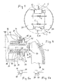
- the wheel brake is designed as a drum brake. It consists of a brake plate 8 and two half-shell-shaped brake shoes 2A, 2B which are arranged within a brake drum 3 rotating with the vehicle wheel. About acting on the brake linkage or brake cable braking force between the one ends of the brake shoes floating expanding spanner 5 is spread by the effective length between its one support 16 against the one end of the left brake shoe 2A on the one hand, and its other support 17 against the one end the right brake shoe 2B on the other hand is increased. The spreading force counteracts the tensile force of one or more springs 6, which endeavor to pull the brake shoes 2A, 2B against each other.
- the support 9 connects in normal braking operation, the other, here lower brake shoe ends together.
- a return mechanism 10 which, when the vehicle wheel reverses, partially or completely lifts this support of the brake shoes 2A, 2B, so that at least one of the two brake shoes is disengaged from the brake drum 3.
- the return automatic 10 in the lower support 9 can, for. B. consist of a support member and at least one evasive when reversing cams. When reversing collapses the lower jaw support, whereby the respective two brake shoe ends approach, and the braking effect is canceled altogether.
- the support 9 may also be integrated a manual adjustment with which can be adjusted by hand, the effective span between the two lower jaw ends.
- the expansion lock 5 is provided with an automatically described adjusting device described in more detail below, with the wear of the brake pads is automatically compensated during driving. Because with increasing wear of the pads of the application of the brake shoes 2A, 2B to the brake drum 3 required Zuspann- or Sp Schwarzweg is greater. The automatic adjusting device compensates for this so-called clearance L ( Fig. 4 ).
- the expanding lock 5 consists of a housing 12 and a spreading lever 14 mounted therein on a shaft 13 which is arranged far outside.
- Part of the expanding lever 14 is a hook 15 arranged approximately in the middle of the housing 12, on which the brake member 1, ie here the brake linkage or the brake cable, attacks.
- Part of the expansion lever 14 is also the longitudinal direction of the housing 12 facing support 16, against which the end of the one, here the left brake shoe 2 A directly or indirectly supported.
- the other support 17 is arranged, via which the expanding lock 5 is supported directly or indirectly against the end of the other brake shoe 2B.
- the transmission lever 18 may be located within the Sp Dr.gepuses, however, it extends in the embodiment outside and along this housing 12.
- the adjuster 20 is pivotally mounted here outside of the housing 12 on a housing fixed approximately in the middle of the housing fixed axis 21.
- the adjuster can also be protected together with the transmission lever in the Housing 12 may be arranged.
- Transmission lever 18 and adjusting lever 20 are arranged and mounted so that their reached by the coupling element 19 movement coupling between the shaft 13 and the axis 21 is located.
- the coupling element 19 opposite end of the adjusting lever 20 is provided with a projection 22.
- the projection 22 represents a first positive locking element, which can engage by positive engagement in a second positive locking element, namely the toothing 31 of a gear 30 of the adjusting device.
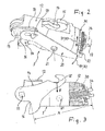
- the gear 30 is also part of an adjusting mechanism, which is arranged in a pointing toward the support 17 bore 12 A of the Sp Dr.gepatuses 12.
- the individual components of the adjuster all sit coaxially to each other on a fixed axis of rotation 49 fixed to the housing, and are therefore arranged to be compactly constructed.
- the adjusting element 34 of the adjusting mechanism and thus that component which is displaced successively when adjusting, is a central screw 34.
- This has a long external thread, and it is extended at its outer end to a head, where it forms the support 17 against the one Brake shoe 2B.
- the head of the screw 34 is designed in the manner of a fork or slit-shaped, so that therein the flat-shaped end of the brake shoe 2B is receiving without the screw 34 can rotate.
- the adjusting, so the central screw 34, is in a threaded connection 36 with a screw surrounding the threaded bushing 35.
- a spring 33 here in the form of a plate spring package
- the already mentioned gear 30 a seated in an annular groove of the threaded sleeve 35 ring 39 and a substantially backlash in the bore 12A seated another bushing 37.
- the other socket 37 is rotatably connected to the threaded bushing 35, but movably connected in the axial direction, which in the embodiment described here a spline 38 between bush 37 and threaded bushing 35 is achieved.
- the bush 37 is supported against an axial surface 41 of the housing 12.
- the threaded bush 35 is provided at its end facing away from the housing 12 with a spring stop 42.
- the ring-shaped spring 33 is supported for the purpose of pressure on the one hand on this stop 42, and on the other hand from the outside against the gear 30 from.
- the overload clutch 45 is composed of ramps which are distributed in the circumferential direction over the mutual contact surfaces of gear 30 and bushing 37 and each consist of a rising ramp surface. Due to this configuration, the gear 30 decoupled from the bushing 37 at sufficiently high moment of resistance of the bushing 37th
- the gear 30 is seated with a kind of cylindrical through hole on a cylindrical portion of the threaded bushing 35, so that the gear 30 is rotatably mounted relative to the threaded sleeve 35. Additional measures can be taken to keep the friction between the gear 30 and the spring 33 supporting it low in such a rotation.
- the ring 39 is axially tightly fitted with its inner circumference in the threaded sleeve 35, whereas its outer periphery is in an inwardly open annular groove 46, partly by a shoulder 47 on the inner edge of the gear 30, and partly by a shoulder 48 on the inner edge of the socket 37 is formed.
- the annular groove 46 thus assembled is axially wider than the ring 39 itself. In this way, depending on the size of the force acting on the screw 34 via the support 17, it is possible both to the situation Fig. 5a come, in which the gear 30 is supported with the shoulder 47 against the ring 39, as well as to the situation Fig. 5b in which it lacks such axial support, but the ring 39 abuts against the shoulder 48 of the sleeve 37 mounted in the housing 37.
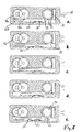
- FIGS. 6a-6e show in various stages, the interaction of Nachstellhebels 20 including the projection 22 with the teeth 31 of the gear 30.
- the adjusting lever 20 forms a first drive part
- the projection 22 forms a first positive locking element
- the teeth of the toothing 31 form second positive locking elements.
- Fig. 6a combined with Fig. 6b is the Zustellweg again, in which the clearance L corresponds to a predetermined distance measure, and is therefore not adjusted.
- the spreading of the expanding lock 5 is accompanied by the pivoting, ie the forward movement H1 of the adjusting lever 20. Its projection 22 engages in the in Fig. 6b in a positively locking manner, and the gear 30 rotates in forward rotation D1.
- the result is the following sequence:
- the Fig. 6d is the situation in a supposedly too big clearance again, but this game is actually based on the intervention of the return automatic, and therefore the great distance of the brake shoes to their friction partner, the brake drum.
- FIGS. 8a - e shows a second embodiment, in which functionally matching components are provided with the same reference numerals as in the embodiment of the FIGS. 1 to 6e ,
- the first drive unit is not composed of pivoting elements, that is, a transmission lever and an adjusting lever, but this drive is realized using, among other things, a substantially translationally moving rack 20.
- the shaft 13 In the housing 12 or in a housing insert 12B of the expanding lock is in turn mounted the shaft 13 on which the not reproduced here Sp Sonhebel 14 is pivotally mounted.
- the shaft 13 takes over a polygon with a pinion 18 a, which drives a second pinion or pinion pair with an inner and outer teeth 18 b in the manner of a transmission or reduction gear.
- Both pinions 18 a, 18 b are mounted in the housing 12 and in a receiving space 52 in an insert 12 B, which is arranged in the housing 12.
- the pinion 18b drives on its outer toothing in the insert 12B substantially longitudinally movably arranged rack 20, which forms the adjuster in this embodiment.
- the rack is provided with the projection 22, ie with that component which can come into positive engagement with the second drive part, the toothing of the gear 30.
- the gear 30 is arranged here in a receiving space 53 of the insert 12B and rotatably supported.
- the gear 30 is formed in this embodiment in two parts as a pair of sprockets, wherein the inner toothing meshes with another gear or drives this.
- the further gear or pinion is in the subsequent parts 33, 34, 35, 37, 39 of the adjusting device, which in the FIGS. 7 and 8th
- a spring-elastic leaf spring 51 acts on the toothed rack 20 in the direction of the toothed wheel 30 and thus influences the positive engagement between the adjuster and the toothed wheel 30.
- the leaf spring 51 is located together with the toothed rack 20 in an elongate receiving space 54 with which the insert 12B is provided , and the enough space for the longitudinal as for the lateral movement of the adjuster 20 offers.
- FIGS. 8a - e are, analogous to the corresponding functional states of FIGS. 6a - e , the various engagement situations between the adjuster 20 including the projection 22 formed thereon and the toothing 31 of the gear 30 shown. Notwithstanding the first embodiment, the projection 22 is not carried out here even elastic or flexible, but it is rigidly formed on the rack 20.
- the radially resilient Dodge is in the functional position according to Fig. 8e achieved by the rack 20 itself can escape laterally against the pressure of the leaf spring 51.
- An advantage of this second embodiment is the compact design, in which the most important moving parts of the adjusting device are housed within the Sp Schwarzschgephaseuses 12 protected against contamination.
- the housing 12 covers outwardly those movement spaces in which move the parts of the adjusting and partially engage with each other.
- the three receiving spaces 52, 53, 54 are covered to the outside by the housing 12.
- this housing made of flexible material, for. As rubber, raise the Sp Dr.gepatuse 12, which has the contour of the Sp Dr.gepatuse 12 and the outer components of the adjustment and their movement spaces thereon.
- An advantage of this second, but also in the first embodiment is further that no further part is necessary, which for canceling the adjustment in the case of activated automatic reversing with components of the brake z. B. is connected to a brake shoe.
- the components of the adjustment are protected by an additional housing dirt.
- this housing made of flexible material, for. As rubber, raise the Sp lanternschgepatuse 12, which has the contour of the Sp Schwarzschgepatuse 12 and the outer components of the adjustment and their movement spaces thereon.
Landscapes
- Engineering & Computer Science (AREA)
- General Engineering & Computer Science (AREA)
- Mechanical Engineering (AREA)
- Transportation (AREA)
- Braking Arrangements (AREA)
Applications Claiming Priority (2)
| Application Number | Priority Date | Filing Date | Title |
|---|---|---|---|
| DE102011002121A DE102011002121A1 (de) | 2011-04-18 | 2011-04-18 | Radbremse für ein trommelgebremstes Fahrzeug sowie Spreizschloss für eine Trommelbremse |
| EP12163283A EP2514646A3 (fr) | 2011-04-18 | 2012-04-05 | Frein de roue pour un véhicule avec frein à tambour ainsi que écarteur pour un frein à tambour |
Related Parent Applications (1)
| Application Number | Title | Priority Date | Filing Date |
|---|---|---|---|
| EP12163283.0 Division | 2012-04-05 |
Publications (1)
| Publication Number | Publication Date |
|---|---|
| EP2631504A1 true EP2631504A1 (fr) | 2013-08-28 |
Family
ID=46025467
Family Applications (2)
| Application Number | Title | Priority Date | Filing Date |
|---|---|---|---|
| EP13168710.5A Withdrawn EP2631504A1 (fr) | 2011-04-18 | 2012-04-05 | Boîtier d'expansion pour un frein à tambour |
| EP12163283A Withdrawn EP2514646A3 (fr) | 2011-04-18 | 2012-04-05 | Frein de roue pour un véhicule avec frein à tambour ainsi que écarteur pour un frein à tambour |
Family Applications After (1)
| Application Number | Title | Priority Date | Filing Date |
|---|---|---|---|
| EP12163283A Withdrawn EP2514646A3 (fr) | 2011-04-18 | 2012-04-05 | Frein de roue pour un véhicule avec frein à tambour ainsi que écarteur pour un frein à tambour |
Country Status (2)
| Country | Link |
|---|---|
| EP (2) | EP2631504A1 (fr) |
| DE (1) | DE102011002121A1 (fr) |
Families Citing this family (1)
| Publication number | Priority date | Publication date | Assignee | Title |
|---|---|---|---|---|
| DE102014118157A1 (de) | 2014-12-08 | 2016-06-09 | Bpw Fahrzeugtechnik Gmbh & Co. Kg | Trommelbremse für ein Fahrzeug sowie Bremsbackenpaar für eine Trommelbremse |
Citations (4)
| Publication number | Priority date | Publication date | Assignee | Title |
|---|---|---|---|---|
| US2049628A (en) * | 1934-09-28 | 1936-08-04 | Rowland Thomas Carlyle Ellison | Vehicle brake |
| US3805926A (en) * | 1969-07-01 | 1974-04-23 | Girling Ltd | Frictional couplings |
| EP0482430B1 (fr) | 1990-10-23 | 1994-11-23 | Knott GmbH | Frein à mâchoires internes à dispositif de rajustage |
| WO2007093399A1 (fr) | 2006-02-16 | 2007-08-23 | Al-Ko Kober Ag | Frein de roue |
Family Cites Families (5)
| Publication number | Priority date | Publication date | Assignee | Title |
|---|---|---|---|---|
| DE1922965A1 (de) * | 1968-05-06 | 1969-11-20 | Aisin Seiki | Selbsttaetige Bremsspiel-Einstellvorrichtung |
| US3540554A (en) * | 1968-08-29 | 1970-11-17 | Bendix Corp | Heat shield for brake adjuster |
| EP0210788A1 (fr) * | 1985-07-23 | 1987-02-04 | LUCAS INDUSTRIES public limited company | Dispositif automatique de rattrapage d'usure |
| GB2275086A (en) * | 1993-02-12 | 1994-08-17 | Allen Patricia Isabel Margaret | Reversing drum brake |
| DE102009036222B4 (de) * | 2009-08-05 | 2013-02-21 | Knott Gmbh | Innenbackenbremse mit thermisch geregelter Nachstelleinrichtung für das Bremsbackenlüftspiel |
-
2011
- 2011-04-18 DE DE102011002121A patent/DE102011002121A1/de not_active Withdrawn
-
2012
- 2012-04-05 EP EP13168710.5A patent/EP2631504A1/fr not_active Withdrawn
- 2012-04-05 EP EP12163283A patent/EP2514646A3/fr not_active Withdrawn
Patent Citations (4)
| Publication number | Priority date | Publication date | Assignee | Title |
|---|---|---|---|---|
| US2049628A (en) * | 1934-09-28 | 1936-08-04 | Rowland Thomas Carlyle Ellison | Vehicle brake |
| US3805926A (en) * | 1969-07-01 | 1974-04-23 | Girling Ltd | Frictional couplings |
| EP0482430B1 (fr) | 1990-10-23 | 1994-11-23 | Knott GmbH | Frein à mâchoires internes à dispositif de rajustage |
| WO2007093399A1 (fr) | 2006-02-16 | 2007-08-23 | Al-Ko Kober Ag | Frein de roue |
Also Published As
| Publication number | Publication date |
|---|---|
| EP2514646A2 (fr) | 2012-10-24 |
| DE102011002121A1 (de) | 2012-10-18 |
| EP2514646A3 (fr) | 2013-03-20 |
Similar Documents
| Publication | Publication Date | Title |
|---|---|---|
| EP3107779B1 (fr) | Frein de véhicule automobile, en particulier frein de véhicule automobile actionnable hydrauliquement et électromécaniquement de manière combinée, avec broche à plusieurs étages | |
| EP2531741B1 (fr) | Actionneur à tige de pression pour des unités d'étrier de frein compactes avec élément fileté prenant appui directement sur le boîtier d'actionneur | |
| EP2531742B1 (fr) | Actionneur à tige de pression pour des unités d'étrier de frein compactes avec levier d'actionnement se déplaçant en butée contre une butée élastique | |
| EP3102845B1 (fr) | Frein à disque de véhicule | |
| DE102014113826B4 (de) | Nachstelleinrichtung einer Scheibenbremse, und eine entsprechende Scheibenbremse | |
| DE202011110404U1 (de) | Bremsbetätigungsmechanismus für eine Scheibenbremse | |
| DD201991A5 (de) | Selbsttaetige nachstellvorrichtung fuer den anlegehub von bremsgestaengen von, insbesondere schienenfahrzeugen | |
| DE102014017156B3 (de) | Betätigungseinrichtung für eine Innenbackenbremse mit manuell betätigbarer Rückstelleinrichtung | |
| DE102006020550B4 (de) | Bremsmechanismus für eine Scheibenbremse | |
| EP0121815B1 (fr) | Dispositif automatique à action instantanée de rattrapage de jeu pour la course d'application de la timonerie de frein, notamment de véhicules ferroviaires | |
| DE102014113055B4 (de) | Scheibenbremse mit einer Nachstellvorrichtung | |
| DE202012002320U1 (de) | Verschleißnachstellvorrichtung für Scheibenbremsen | |
| DE102013214188B4 (de) | Vorrichtung zum Betätigen eines Verriegelungsmechanismus, insbesondere zum Betätigen einer Parksperreneinrichtung | |
| DE4105299A1 (de) | Zangenartiges bremsgestaenge, insbesondere fuer scheibenbremsen von schienenfahrzeugen | |
| EP2631504A1 (fr) | Boîtier d'expansion pour un frein à tambour | |
| DE202013009442U1 (de) | Verschleißnachstellvorrichtung für Scheibenbremsen | |
| DE102019101342B4 (de) | Verschleißnachsteller einer Kompakt-Bremszangeneinheit, und Kompakt-Bremszangeneinheit mit einem solchen Verschleißnachsteller | |
| DE202004009839U1 (de) | Verstellantrieb | |
| DE2636047C2 (de) | Nachstellvorrichtung für die Anschläge einer Vollscheibenbremse | |
| DE4105286A1 (de) | Zangenartiges bremsgestaenge, insbesondere fuer scheibenbremsen von schienenfahrzeugen | |
| DE3213835A1 (de) | Ueberlastkupplung fuer drehuebertragungen | |
| EP3404281B1 (fr) | Dispositif de fonctionnement d'un dispositif mécanique, en particulier d'un dispositif de freinage | |
| DE102014221741A1 (de) | Schwenkmodul einer Anhängerkupplung | |
| DE1530260C (de) | Selbsttätige doppeltwirkende Nachstellvorrichtung für eine Eisenbahn- oder andere Fahrzeug-Bremsanlage | |
| DE9018014U1 (de) | Scheibenbremse für Fahrzeuge |
Legal Events
| Date | Code | Title | Description |
|---|---|---|---|
| PUAI | Public reference made under article 153(3) epc to a published international application that has entered the european phase |
Free format text: ORIGINAL CODE: 0009012 |
|
| AC | Divisional application: reference to earlier application |
Ref document number: 2514646 Country of ref document: EP Kind code of ref document: P |
|
| AK | Designated contracting states |
Kind code of ref document: A1 Designated state(s): AL AT BE BG CH CY CZ DE DK EE ES FI FR GB GR HR HU IE IS IT LI LT LU LV MC MK MT NL NO PL PT RO RS SE SI SK SM TR |
|
| AX | Request for extension of the european patent |
Extension state: BA ME |
|
| 17P | Request for examination filed |
Effective date: 20140224 |
|
| RBV | Designated contracting states (corrected) |
Designated state(s): AL AT BE BG CH CY CZ DE DK EE ES FI FR GB GR HR HU IE IS IT LI LT LU LV MC MK MT NL NO PL PT RO RS SE SI SK SM TR |
|
| STAA | Information on the status of an ep patent application or granted ep patent |
Free format text: STATUS: REQUEST FOR EXAMINATION WAS MADE |
|
| STAA | Information on the status of an ep patent application or granted ep patent |
Free format text: STATUS: THE APPLICATION IS DEEMED TO BE WITHDRAWN |
|
| 18D | Application deemed to be withdrawn |
Effective date: 20171103 |