EP2631670B1 - System und Verfahren zur Radarlokalisierung - Google Patents
System und Verfahren zur Radarlokalisierung Download PDFInfo
- Publication number
- EP2631670B1 EP2631670B1 EP13156440.3A EP13156440A EP2631670B1 EP 2631670 B1 EP2631670 B1 EP 2631670B1 EP 13156440 A EP13156440 A EP 13156440A EP 2631670 B1 EP2631670 B1 EP 2631670B1
- Authority
- EP
- European Patent Office
- Prior art keywords
- pulse
- signal
- pulses
- radar
- determining
- Prior art date
- Legal status (The legal status is an assumption and is not a legal conclusion. Google has not performed a legal analysis and makes no representation as to the accuracy of the status listed.)
- Active
Links
Images

Classifications
-
- G—PHYSICS
- G01—MEASURING; TESTING
- G01S—RADIO DIRECTION-FINDING; RADIO NAVIGATION; DETERMINING DISTANCE OR VELOCITY BY USE OF RADIO WAVES; LOCATING OR PRESENCE-DETECTING BY USE OF THE REFLECTION OR RERADIATION OF RADIO WAVES; ANALOGOUS ARRANGEMENTS USING OTHER WAVES
- G01S13/00—Systems using the reflection or reradiation of radio waves, e.g. radar systems; Analogous systems using reflection or reradiation of waves whose nature or wavelength is irrelevant or unspecified
- G01S13/02—Systems using reflection of radio waves, e.g. primary radar systems; Analogous systems
- G01S13/06—Systems determining position data of a target
-
- G—PHYSICS
- G01—MEASURING; TESTING
- G01S—RADIO DIRECTION-FINDING; RADIO NAVIGATION; DETERMINING DISTANCE OR VELOCITY BY USE OF RADIO WAVES; LOCATING OR PRESENCE-DETECTING BY USE OF THE REFLECTION OR RERADIATION OF RADIO WAVES; ANALOGOUS ARRANGEMENTS USING OTHER WAVES
- G01S13/00—Systems using the reflection or reradiation of radio waves, e.g. radar systems; Analogous systems using reflection or reradiation of waves whose nature or wavelength is irrelevant or unspecified
- G01S13/02—Systems using reflection of radio waves, e.g. primary radar systems; Analogous systems
- G01S13/06—Systems determining position data of a target
- G01S13/08—Systems for measuring distance only
- G01S13/10—Systems for measuring distance only using transmission of interrupted, pulse modulated waves
- G01S13/103—Systems for measuring distance only using transmission of interrupted, pulse modulated waves particularities of the measurement of the distance
-
- G—PHYSICS
- G01—MEASURING; TESTING
- G01S—RADIO DIRECTION-FINDING; RADIO NAVIGATION; DETERMINING DISTANCE OR VELOCITY BY USE OF RADIO WAVES; LOCATING OR PRESENCE-DETECTING BY USE OF THE REFLECTION OR RERADIATION OF RADIO WAVES; ANALOGOUS ARRANGEMENTS USING OTHER WAVES
- G01S13/00—Systems using the reflection or reradiation of radio waves, e.g. radar systems; Analogous systems using reflection or reradiation of waves whose nature or wavelength is irrelevant or unspecified
- G01S13/02—Systems using reflection of radio waves, e.g. primary radar systems; Analogous systems
- G01S13/06—Systems determining position data of a target
- G01S13/08—Systems for measuring distance only
- G01S13/10—Systems for measuring distance only using transmission of interrupted, pulse modulated waves
- G01S13/26—Systems for measuring distance only using transmission of interrupted, pulse modulated waves wherein the transmitted pulses use a frequency- or phase-modulated carrier wave
- G01S13/28—Systems for measuring distance only using transmission of interrupted, pulse modulated waves wherein the transmitted pulses use a frequency- or phase-modulated carrier wave with time compression of received pulses
- G01S13/282—Systems for measuring distance only using transmission of interrupted, pulse modulated waves wherein the transmitted pulses use a frequency- or phase-modulated carrier wave with time compression of received pulses using a frequency modulated carrier wave
-
- G—PHYSICS
- G01—MEASURING; TESTING
- G01S—RADIO DIRECTION-FINDING; RADIO NAVIGATION; DETERMINING DISTANCE OR VELOCITY BY USE OF RADIO WAVES; LOCATING OR PRESENCE-DETECTING BY USE OF THE REFLECTION OR RERADIATION OF RADIO WAVES; ANALOGOUS ARRANGEMENTS USING OTHER WAVES
- G01S7/00—Details of systems according to groups G01S13/00, G01S15/00, G01S17/00
- G01S7/02—Details of systems according to groups G01S13/00, G01S15/00, G01S17/00 of systems according to group G01S13/00
- G01S7/28—Details of pulse systems
- G01S7/285—Receivers
-
- G—PHYSICS
- G01—MEASURING; TESTING
- G01S—RADIO DIRECTION-FINDING; RADIO NAVIGATION; DETERMINING DISTANCE OR VELOCITY BY USE OF RADIO WAVES; LOCATING OR PRESENCE-DETECTING BY USE OF THE REFLECTION OR RERADIATION OF RADIO WAVES; ANALOGOUS ARRANGEMENTS USING OTHER WAVES
- G01S7/00—Details of systems according to groups G01S13/00, G01S15/00, G01S17/00
- G01S7/02—Details of systems according to groups G01S13/00, G01S15/00, G01S17/00 of systems according to group G01S13/00
- G01S7/28—Details of pulse systems
- G01S7/285—Receivers
- G01S7/292—Extracting wanted echo-signals
- G01S7/2921—Extracting wanted echo-signals based on data belonging to one radar period
-
- G—PHYSICS
- G01—MEASURING; TESTING
- G01S—RADIO DIRECTION-FINDING; RADIO NAVIGATION; DETERMINING DISTANCE OR VELOCITY BY USE OF RADIO WAVES; LOCATING OR PRESENCE-DETECTING BY USE OF THE REFLECTION OR RERADIATION OF RADIO WAVES; ANALOGOUS ARRANGEMENTS USING OTHER WAVES
- G01S7/00—Details of systems according to groups G01S13/00, G01S15/00, G01S17/00
- G01S7/02—Details of systems according to groups G01S13/00, G01S15/00, G01S17/00 of systems according to group G01S13/00
- G01S7/36—Means for anti-jamming, e.g. ECCM, i.e. electronic counter-counter measures
Definitions
- the present invention relates to a radar location system, using a transmitter and a receiver of radar signals and allowing reflection of the waves emitted on the objects to detect and locate these objects. It applies in the field of object detection and localization, in particular where the location of objects close to the system is necessary.
- a “solid state” emitter uses devices in particular transistors in which the current flows in semiconductor materials which are solid by opposed to a vacuum tube emitter where the current consists of a confined electron beam which consists of an electron "gas"
- the radar signals generally use a succession of pulses of duration T1.
- they must have a ratio between the average power emitted and the maximum power emitted as high as possible, so it is necessary to have long pulses.
- the cost of solid-state emission systems depends mainly on the maximum power, but the radar range depends mainly on average power.
- a reflected pulse will return to the transmitter at the same time as the next pulse emitted.
- the area in which the radar can not locate the most troublesome is one that is located a short distance away. Indeed, the masked area at the end of the domain is not very troublesome because it is sufficient to increase the pulse repetition period (PRI) if it is desired to observe pulses reflected in this range of distance.
- PRI pulse repetition period
- the non-usable space domain (geographical area in which the radar is not able to locate an object) is the zone located at a distance of distance less than the distance traveled by a pulse during the time T1.
- the standard detection methods applied to a fraction of the received pulse, cause a degraded detection and a degraded precision, because the code is incomplete. .
- This degradation can be reflected, for example, by multiple correlation peaks leading to ambiguities of position or a sharp decline in the power of the pulses and therefore to a loss of efficiency of the radar.
- the reception is broadband, that is to say that the bandwidth of the receiver covers the entire spectrum corresponding to the N frequencies.
- the signals received in the N frequencies are received simultaneously and assigned to the right frequency by means of adequate frequency (analog or digital) filtering.
- This last embodiment makes it possible to counter the problem of the zone in which the radar can not locate an object, this zone being important at a short distance.
- it creates a new problem which is the appearance of N-2 zones in which the radar can not locate object, in the central part of the domain in distance.
- it is necessary to emit, on several observation sequences, a signal whose sequence sequence PRI is slightly varied so as to move the blind central zone.
- this solution does not allow optimal performance in the central area.
- the reference patent application FR 2 146 105 discloses an electromagnetic correlation detection method and a detection system using this method.
- the object of the present invention is therefore a radar localization system allowing a precise location at short distance and does not have the drawbacks of the systems known in the state of the art.
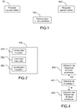
- a radar locating system comprising radar signal transmitting means 101 , said signal comprising at least one transmitted pulse, an emitted pulse having a duration T1 and an associated index i and a beginner. at a moment T2 (i). Moreover, said pulse being modulated by at least one code retaining good autocorrelation properties when a fraction of said code is used.
- the system also comprises means 102 for receiving reflected radar signals, means 103 for determining a correlation between a reconstruction of an emitted pulse and the radar signal received during the time interval beginning at T2 (i) + 2 * T1 and ending at T2 (i + 1).
- said means for determining a correlation are further adapted to reconstruct an assembly of at least one truncated pulse j, a truncated pulse j being of duration T3 (j), less than the duration of the transmitted pulse T1 and corresponding to the final part of said transmitted pulse, said truncated pulses being of increasing respective durations, to determine at least a first signal correlated by correlation of said truncated pulse j and of the signal received during the time interval starting from T2 (i) + T1 and ending at T2 (i) + T1 + T3 (j) determining a second signal, from all or part of the first signals correlated j, by the copying of the time interval, of said correlated signal j , beginning at T2 (i) + T1 + T3 (d-1) and ending at T2 (i) + T1 + T3 (d), over the time interval, of said second signal, beginning at T2 (i) + T1 + T3 (j-1) and ending at T2 (
- the second signal is obtained by copying different parts of the first signals.
- This second signal is a signal for which the different peaks represents the different objects, having reflected the radar wave and which are located in the radar environment.
- This system thus makes it possible to locate an object located very close, indeed it allows to make the location even if a part of the reflected pulse arrives at the receiver during the emission of this said pulse.
- said means 103 for determining a correlation are further adapted for multiplying the temporal samples of said truncated pulses by a respective weighting coefficient belonging to a weighting window.
- This technical characteristic makes it possible to improve the accuracy of the location.
- said means for determining a correlation are furthermore adapted, from a reconstructed pulse j, to calculate a first vector corresponding to the discrete fourier transform of the signal received over the interval from T2 ( i) + T1 to T2 (i) + T1 + T3 (j), determine a second vector corresponding to the discrete fourier transform of the time reversal of the complex conjugate of the reconstructed pulse j and calculate said first signal correlated by inverse discrete Fourier transform of the term-to-term multiplication of the first and second vectors.
- This technical feature reduces the resource requirements of computing modules and devices used by the system.
- said transmission means 101 are furthermore suitable for transmitting radar signals comprising at least one modulated pulse using a linear or nonlinear frequency ramp and said receiving module is adapted for receiving signals.
- radar comprising said modulated pulses using a linear or non-linear frequency ramp.
- said means 103 for determining a correlation are furthermore adapted, from a reconstructed pulse j, to filter the samples of said second signal over an interval starting from T2 (i) + T1 + T3 (j) and ending at T2 (i) + T1 + T3 (j + 1) so that a sample of said interval is equal to the weighted average of the samples adjacent to said sample.
- said transmission means 101 are adapted to use a set of different frequencies for the transmission of said pulses of said radar signals and said reception means 102 are adapted to receive said pulses of said radar signals reflected on said different frequencies.
- the system further comprises means for determining a third synchronization signal, for a transmitted pulse using a frequency, by term-to-term addition, for all or part of the pulses transmitted using the same frequency, samples of the interval of said reflected radar signal beginning at T2 (j) + T1 and ending at T2 (j) + 2 * T1, said addition being stored in the time interval, of said third signal, starting at T2 ( i) + T1 and ending at T2 (i) + 2 * T1.
- said means 103 for determining a correlation are further adapted for the correlation between the reconstruction of an emitted pulse and the time interval, of said third signal, starting at T2 (i) + 2 * T1 and ending at T2 (i + 1)
- the radar localization method uses the system presented in the invention and comprises the following steps: a step 401 for detecting a possible source of interference, a step 402, in the case of non-detection of a source for jamming, transmitting and receiving a radar signal for which the pulses forming part of the same group of successive pulses use an identical transmission frequency, the transmission frequency varying from one group to the next and a step 403, in the case of detecting a source of interference, of transmitting and of receiving a radar signal using different frequencies for two successive pulses, the frequencies following a distribution law periodic or non-periodic.
- Barker codes In contrast, the property is not verified on Barker codes. Indeed a truncated Barker code is no longer a Barker code.
- correlation processing with a reconstructed pulse is employed (this processing is also known as pulse compression) .
- the correlation can also be achieved by the use of a discrete Fourier transform.
- the correlation method uses a conventional matched filter. This method is, however, heavier in computation than the discrete Fourier transform method for large " BT " compressions.
- the module for determining a correlation is presented figure 2 and includes the following devices.
- a device 301 for reconstructing a pulse makes it possible to obtain a pulse corresponding to the final part of the initial pulse and of duration T3 (j).
- N a limited number of reconstructed pulses.
- This embodiment having the disadvantage of not having a reconstructed replica perfectly adapted to each of the samples of the received signal. It is also possible to use a discrete Fourier transform processing.
- the concatenation device 303 is furthermore adapted to make it possible to select, in each of the N signals correlated by N reconstructed pulses, the useful area of this correlation and to construct a second signal by copying the samples of the time interval, the correlated signal j, starting at T2 (i) + T1 + T3 (j-1) and ending at T2 (i) + T1 + T3 (j), over the time interval, of the second signal, starting at T2 (i) + T1 + T3 (d-1) and ending at T2 (i) + T1 + T3 (j).
- the samples of the correlated signal of the interval beginning at T2 (i) + 2 * T1 and ending at T2 (i + 1) are copied over the time interval, of the second signal, starting at T2 (i) + T1 + T3 (j-1) and ending at T2 (i) + T1 + T3 (j).
- the figure 3 presents a mode of operation of the device 303.
- the modulated pulses using a nonlinear frequency ramp are used.
- a nonlinear frequency ramp also known as non-linear chirp or "S" chirp
- the advantage of this type of pulse is to present, in the complete correlation zone a spectrum such that the amplitude weighting is unnecessary, so not to cause loss of weighting in this area. On the other hand, in the incomplete correlation zone, this property is lost as the visible fraction of the impulse diminishes. An amplitude weighting is then desirable.
- the frequency spreading band of the reconstructed pulse depends on the length of this pulse.
- the spatial resolution (minimum separation between two points so that the radar detects these two points independently) depends on the frequency spreading band.
- the correlation module may therefore include a filtering device. This filtering can use a formula using a monotonic function (power, Log., Etc.) and it aims to make the resolution in the same distance for all the signals correlated with the reconstructed pulses.
- the filter function can be different on the different intervals starting at T2 (i) + T1 + T3 (j) and ending at T2 (i) + T1T3 (j).
- the system allows the use of multiple frequencies to perform the different treatments using frequency diversity to smooth target fluctuations. From 5 to 15 sufficiently spaced transmission frequencies are sufficient to obtain the effect of decorrelation and frequency diversity.
- the transmission module and the reception module are adapted for transmitting and receiving signals so as to use several frequencies. It is known in the state of the art devices for making this broadcast and reception.
- the organization of the different frequencies can be of two different types.
- a first type the frequencies used by successive pulses are identical.
- the transmission frequency is changed after a certain number of pulse occurrences.
- a second type the frequency used by two successive pulses is different and the frequency utilization follows a distribution law that can be periodic.
- the first type of frequency utilization has the advantage of restricting the time spacing between the summed pulses together, thus improving the accuracy of the location of objects operating at a non-constant speed.
- having sequences of several pulses at constant frequency it has certain weaknesses. In particular the risk of false alarm due to ambiguous reflected pulses of large radar cross section is increased and the system is more disturbed by sources of interference due to the partial absence of frequency agility.
- the second type of frequency utilization has the advantage of limiting the risk of false alarm due to ambiguous reflected pulses of large radar cross-section, it also allows greater robustness with regard to sources of interference, due to Pulse pulse frequency agility. However this second type of frequency utilization is less robust vis-à-vis the non-constant speed movements of the targets.
- the module 103 for determining a correlation further comprises a synchronization device, making it possible to synchronize the reflected pulses corresponding to the same frequency and to add the samples of the intervals in the same signal. time of the received signal corresponding to the reception of these reflected pulses.
- a transmitted pulse i using a transmission frequency the pulses emitted using the same frequency are determined, then for all or part of the pulses emitted to the samples of the interval of said reflected radar signal starting at T2 (j) + T1 and ending at T2 (j) + 2 * T1 are summed and stored in the interval of a third signal starting at T2 (i) + T1 and ending at T2 (i) + 2 * T1.
Landscapes
- Engineering & Computer Science (AREA)
- Radar, Positioning & Navigation (AREA)
- Remote Sensing (AREA)
- Computer Networks & Wireless Communication (AREA)
- Physics & Mathematics (AREA)
- General Physics & Mathematics (AREA)
- Radar Systems Or Details Thereof (AREA)
Claims (8)
- Radarortungssystem, das Folgendes umfasst:- Mittel (101) zum Senden eines Radarsignals, wobei das Signal wenigstens einen emittierten Impuls umfasst, wobei ein emittierter Impuls eine Dauer T1 und einen Index i in Assoziation mit und beginnend an einem Zeitpunkt T2(i) hat, wobei der Impuls auch durch wenigstens einen Code moduliert wird, der gute Autokorrelationseigenschaften beibehält, wenn eine Fraktion des Codes benutzt wird;- Mittel (102) zum Empfangen von reflektierten Radarsignalen;- Mittel (103) zum Ermitteln einer Korrelation zwischen einer Rekonstruktion eines emittierten Impulses und dem während des Zeitintervalls beginnend bei T2(i)+2*T1 und endend bei T2(i+1) empfangenen Radarsignal,wobei das System dadurch gekennzeichnet ist, dass die Mittel zum Ermitteln einer Korrelation auch ausgelegt sind zum:- Rekonstruieren eines Satzes von wenigstens einem abgekürzten Impuls j, wobei ein abgekürzter Impuls j eine Dauer T3(j) hat, die kürzer ist als die Dauer T1 des emittierten Impulses und dem letzten Teil des emittierten Impulses entspricht, wobei die verkürzten Impulse jeweils zunehmende Dauern haben;- Ermitteln wenigstens eines ersten korrelierten Signals j durch Korrelieren des verkürzten Impulses j und des Signals, das während des Zeitintervalls beginnend bei T2(i)+T1 und endend bei T2(i)+T1+T3(j) empfangen wird;- Ermitteln eines zweiten Signals auf der Basis von einigen oder allen der ersten korrelierten Signale j, durch Kopieren des Zeitintervalls des korrelierten Signals j, beginnend bei T2(i)+T1+T3(j-1) und endend bei T2(i)+T1+T3(j), auf das Zeitintervall des zweiten Signals beginnend bei T2(i)+T1+T3(j-1) und endend bei T2(i)+T1+T3(j);- Ermitteln des Orts von Objekten, die das Radarsignal reflektiert haben, durch Ermitteln von Peaks des zweiten Signals.
- System nach Anspruch 1, wobei die Mittel (103) zum Ermitteln einer Korrelation ferner zum Multiplizieren von Zeit-Samples der verkürzten Impulse mit einem jeweiligen Gewichtungskoeffizienten ausgelegt sind, der zu einem Gewichtungsfenster gehört.
- System nach Anspruch 1 oder 2, wobei die Mittel zum Ermitteln einer Korrelation auch, auf der Basis eines rekonstruierten Impulses j, ausgelegt sind zum:- Berechnen eines ersten Vektors entsprechend der diskreten Fourier-Transformation des Signals, das im Intervall von T2(i)+T1 bis T2(i)+T1+T3(j) empfangen wurde;- Ermitteln eines zweiten Vektors entsprechend der diskreten Fourier-Transformation der zeitlichen Rücksendung des komplexen Konjugats des rekonstruierten Impulses j;- Berechnen des ersten korrelierten Signals j durch die umgekehrte diskrete Fourier-Transformation der Term-mal-Term-Multiplikation des ersten und zweiten Vektors.
- System nach einem der Ansprüche 1 bis 3, wobei die Sendemittel (101) ferner zum Senden von Radarsignalen ausgelegt sind, die wenigstens einen Impuls umfassen, der mit einer linearen oder nichtlinearen Frequenzrampe moduliert wurde, und das Empfangsmodul zum Empfangen von Radarsignalen ausgelegt ist, die die mit einer linearen oder nichtlinearen Frequenzrampe modulierten Impulse umfassen.
- System nach Anspruch 4, wobei die Mittel (103) zum Ermitteln einer Korrelation ferner, auf der Basis eines rekonstruierten Impulses j, zum Filtern der Samples des zweiten Signals in einem Intervall beginnend bei T2(i)+T1+T3(j) und endend bei T2(i)+T1+T3(j+1) ausgelegt ist, so dass ein Sample des Intervalls gleich dem gewichteten Durchschnitt der dem Sample benachbarten Samples ist.
- System nach einem der Ansprüche 1 bis 5, wobei die Sendemittel (101) zur Verwendung eines Satzes von unterschiedlichen Frequenzen zum Emittieren der Impulse der Radarsignale ausgelegt ist, und die Empfangsmittel (102) zum Empfangen der Impulse der auf den unterschiedlichen Frequenzen reflektierten Radarsignale ausgelegt sind.
- System nach Anspruch 6,- das ferner Mittel zum Ermitteln eines dritten Synchronisationssignals für einen mit einer Frequenz emittierten Impuls i durch eine Term-zu-Term-Addition, für einige oder alle emittierten Impulse j mit derselben Frequenz, der Samples des Intervalls des reflektierten Radarsignals beginnend bei T2(j)+T1 und endend bei T2(j)+2*T1 umfasst, wobei die Addition in dem Zeitintervall des dritten Signals beginnend bei T2(i)+T1 und endend bei T2(i)+2*T1 gespeichert wird;- und wobei die Mittel (103) zum Ermitteln einer Korrelation ferner zum Korrelieren zwischen der Rekonstruktion eines emittierten Impulses und dem Zeitintervall des dritten Signals beginnend bei T2(i)+2*T1 und endend bei T2(i+1) ausgelegt ist.
- Radarortungsverfahren unter Verwendung des Systems nach Anspruch 7, das die folgenden Schritte beinhaltet:- einen Schritt (401) zum Erkennen einer eventuellen Störquelle;- einen Schritt (402), falls keine Störquelle erkannt wird, des Sendens und Empfangens eines Radarsignals, dessen Impulse, die zur selben Gruppe von aufeinander folgenden Impulsen gehören, eine identische Sendefrequenz benutzen, wobei die Sendefrequenz von einer Gruppe zur nächsten variiert;- einen Schritt (403), falls eine Störquelle erkannt wird, des Sendens und Empfangens eines Radarsignals mit unterschiedlichen Frequenzen für zwei aufeinander folgende Impulse, wobei die Frequenzen einem periodischen oder nichtperiodischen Verteilungsgesetz folgen.
Applications Claiming Priority (1)
| Application Number | Priority Date | Filing Date | Title |
|---|---|---|---|
| FR1200547A FR2987453B1 (fr) | 2012-02-24 | 2012-02-24 | Systeme et procede de localisation radar |
Publications (2)
| Publication Number | Publication Date |
|---|---|
| EP2631670A1 EP2631670A1 (de) | 2013-08-28 |
| EP2631670B1 true EP2631670B1 (de) | 2016-12-21 |
Family
ID=47722186
Family Applications (1)
| Application Number | Title | Priority Date | Filing Date |
|---|---|---|---|
| EP13156440.3A Active EP2631670B1 (de) | 2012-02-24 | 2013-02-22 | System und Verfahren zur Radarlokalisierung |
Country Status (3)
| Country | Link |
|---|---|
| US (1) | US9035824B2 (de) |
| EP (1) | EP2631670B1 (de) |
| FR (1) | FR2987453B1 (de) |
Cited By (1)
| Publication number | Priority date | Publication date | Assignee | Title |
|---|---|---|---|---|
| RU2745108C1 (ru) * | 2020-09-17 | 2021-03-22 | Кирилл Евгеньевич Кузнецов | Способ определения разности расстояний до постановщика многократной ответно-импульсной помехи в активно-пассивной многопозиционной радиолокационной системе |
Families Citing this family (4)
| Publication number | Priority date | Publication date | Assignee | Title |
|---|---|---|---|---|
| US9465098B2 (en) * | 2013-09-12 | 2016-10-11 | Raytheon Company | Mitigating low duty factor electronic attack (EA) |
| RU2568628C2 (ru) * | 2014-03-21 | 2015-11-20 | Виктор Леонидович Семенов | Устройство определения параметров движения астероида |
| FR3026194B1 (fr) * | 2014-09-24 | 2018-01-26 | Thales Sa | Forme d'onde radar, procede de detection radar utilisant une telle onde, et radar mettant en oeuvre le procede |
| FR3027161B1 (fr) * | 2014-10-09 | 2017-05-12 | Centre Nat Rech Scient | Procede de generation de rayonnements electromagnetiques haute puissance |
Family Cites Families (13)
| Publication number | Priority date | Publication date | Assignee | Title |
|---|---|---|---|---|
| US4135189A (en) * | 1964-01-09 | 1979-01-16 | Compagnie Generale De Telegraphie Sans Fil | Random frequency radar system |
| FR2146105B1 (de) * | 1971-07-16 | 1975-10-10 | Thomson Csf | |
| US4358766A (en) * | 1974-07-01 | 1982-11-09 | Sanders Associates, Inc. | Jamming signal reduction system |
| GB2259820B (en) * | 1985-05-20 | 1993-08-25 | Gec Avionics | A noise radar |
| US5017921A (en) * | 1989-12-13 | 1991-05-21 | Grumman Aerospace Corporation | Radar system and a method for operating a radar system |
| US5311541A (en) * | 1992-05-08 | 1994-05-10 | Axonn Corporation | Frequency agile radio |
| AU4393693A (en) * | 1992-05-08 | 1994-12-20 | Axonn Corporation | A frequency agile radio |
| NL9302002A (nl) * | 1993-11-19 | 1995-06-16 | Hollandse Signaalapparaten Bv | Radarapparaat voorzien van ECCM voorzieningen. |
| US5537117A (en) * | 1995-08-08 | 1996-07-16 | Litton Systems, Inc. | Closed loop countermeasure to passive direction finding and location of radar transmitters using Doppler techniques |
| EP1081505A1 (de) * | 1999-09-06 | 2001-03-07 | CSEM Centre Suisse d'Electronique et de Microtechnique S.A. - Recherche et Développement | Digitaler Korrelator und Korrelationsverfahren in einem Telemetriemessungssystem |
| US6937639B2 (en) * | 2001-04-16 | 2005-08-30 | Time Domain Corporation | System and method for positioning pulses in time using a code that provides spectral shaping |
| US8179305B2 (en) * | 2009-08-12 | 2012-05-15 | Tektronix, Inc. | Enhanced impulse response measurement of an FM radar transmitter pulse |
| CN102893173B (zh) * | 2010-03-05 | 2014-12-03 | 温莎大学 | 雷达系统及其制作方法 |
-
2012
- 2012-02-24 FR FR1200547A patent/FR2987453B1/fr not_active Expired - Fee Related
-
2013
- 2013-02-22 US US13/774,770 patent/US9035824B2/en active Active
- 2013-02-22 EP EP13156440.3A patent/EP2631670B1/de active Active
Non-Patent Citations (1)
| Title |
|---|
| None * |
Cited By (1)
| Publication number | Priority date | Publication date | Assignee | Title |
|---|---|---|---|---|
| RU2745108C1 (ru) * | 2020-09-17 | 2021-03-22 | Кирилл Евгеньевич Кузнецов | Способ определения разности расстояний до постановщика многократной ответно-импульсной помехи в активно-пассивной многопозиционной радиолокационной системе |
Also Published As
| Publication number | Publication date |
|---|---|
| FR2987453B1 (fr) | 2014-04-25 |
| US9035824B2 (en) | 2015-05-19 |
| EP2631670A1 (de) | 2013-08-28 |
| FR2987453A1 (fr) | 2013-08-30 |
| US20130234878A1 (en) | 2013-09-12 |
Similar Documents
| Publication | Publication Date | Title |
|---|---|---|
| EP2100161B1 (de) | Verfahren zur mehrwege-passivradar-verarbeitung eines fm-gelegenheitssignals | |
| EP2339369B1 (de) | Radarortungsverfahren insbesondere für Bordradargeräte zur Umsetzung einer Hinderniserfassungs- und -vermeidungsfunktion | |
| EP2631670B1 (de) | System und Verfahren zur Radarlokalisierung | |
| EP0932836B1 (de) | Verfahren für impulskompression mit synthetischem-band wellenformen | |
| EP2287633B1 (de) | Radar zur Erkennung von Luftzielen, der als Ausrüstung eines Luftfahrzeugs dient, insbesondere zur Hindernisumfliegung | |
| FR3047566A1 (fr) | Procede de brouillage de radars du type a ouverture synthetique et dispositif associe | |
| EP0036794A1 (de) | Akustisches Abbildungssystem | |
| WO2007131980A1 (fr) | Procede de detection des reflecteurs d'une impulsion electromagnetique | |
| EP3022573B1 (de) | Vorrichtung zur erkennung von elektromagnetischen signalen | |
| FR3143767A1 (fr) | Procédé de caractérisation de cible pour un dispositif de détection du type radar ou sonar multi-panneaux à balayage électronique | |
| EP3198299B1 (de) | Radardetektionsverfahren und radar zur implementierung des besagten verfahrens | |
| EP2453251B1 (de) | Verfahren zum Durchfüren einer hochauflösenden Analyse einer Raumzone mittels einer frequenzbeweglichen Pulswelle | |
| FR3088730A1 (fr) | Procédé de création d'au moins une voie de réception virtuelle par l'utilisation d'une antenne radar et système radar | |
| FR2970085A1 (fr) | Procede d'extension de la portee instrumentee d'un radar | |
| EP4330722B1 (de) | Radarsystem und zugehöriges verfahren zur optimierung der beseitigung von radarstörungen | |
| FR3125888A1 (fr) | Procede d'optimisation de la determination de la distance d'une cible par rapport a un radar a codage de phase en mode pulse | |
| EP3400457B1 (de) | Verfahren zum löschen eines signals aus einem bordradar | |
| EP2810093A1 (de) | Verfahren zur mehrdeutigkeitsauflösung bei abstandsmessungen | |
| Trider | Signal investigation for low frequency active (LFA) sonar | |
| EP2687863B1 (de) | Verfahren zum Filtern von Radarbildern, die durch irreführende Echos aus der Ferne verzerrt werden | |
| FR2972055A1 (fr) | Procede de determination d'un rang d'ambiguite en distance d'un signal recu par un radar doppler a impulsions | |
| EP2558881B1 (de) | Pfadformende adaptive verarbeitung für aktives sonar | |
| EP4575551A1 (de) | Impulsradar mit hybridem impulsansatz und frequenzmodulation | |
| FR3009390A1 (fr) | Systeme d'analyse de la faune aerienne par radar imageur | |
| FR2986333A1 (fr) | Procede de polyvalent de surveillance utilisant un radar |
Legal Events
| Date | Code | Title | Description |
|---|---|---|---|
| PUAI | Public reference made under article 153(3) epc to a published international application that has entered the european phase |
Free format text: ORIGINAL CODE: 0009012 |
|
| AK | Designated contracting states |
Kind code of ref document: A1 Designated state(s): AL AT BE BG CH CY CZ DE DK EE ES FI FR GB GR HR HU IE IS IT LI LT LU LV MC MK MT NL NO PL PT RO RS SE SI SK SM TR |
|
| AX | Request for extension of the european patent |
Extension state: BA ME |
|
| 17P | Request for examination filed |
Effective date: 20140224 |
|
| RBV | Designated contracting states (corrected) |
Designated state(s): AL AT BE BG CH CY CZ DE DK EE ES FI FR GB GR HR HU IE IS IT LI LT LU LV MC MK MT NL NO PL PT RO RS SE SI SK SM TR |
|
| GRAP | Despatch of communication of intention to grant a patent |
Free format text: ORIGINAL CODE: EPIDOSNIGR1 |
|
| RIC1 | Information provided on ipc code assigned before grant |
Ipc: G01S 7/292 20060101ALI20160722BHEP Ipc: G01S 13/06 20060101ALI20160722BHEP Ipc: G01S 13/10 20060101ALI20160722BHEP Ipc: G01S 13/28 20060101AFI20160722BHEP Ipc: G01S 7/36 20060101ALI20160722BHEP Ipc: G01S 7/285 20060101ALI20160722BHEP |
|
| INTG | Intention to grant announced |
Effective date: 20160809 |
|
| GRAS | Grant fee paid |
Free format text: ORIGINAL CODE: EPIDOSNIGR3 |
|
| GRAA | (expected) grant |
Free format text: ORIGINAL CODE: 0009210 |
|
| RAP1 | Party data changed (applicant data changed or rights of an application transferred) |
Owner name: THALES |
|
| AK | Designated contracting states |
Kind code of ref document: B1 Designated state(s): AL AT BE BG CH CY CZ DE DK EE ES FI FR GB GR HR HU IE IS IT LI LT LU LV MC MK MT NL NO PL PT RO RS SE SI SK SM TR |
|
| REG | Reference to a national code |
Ref country code: GB Ref legal event code: FG4D Free format text: NOT ENGLISH |
|
| REG | Reference to a national code |
Ref country code: CH Ref legal event code: EP |
|
| REG | Reference to a national code |
Ref country code: IE Ref legal event code: FG4D Free format text: LANGUAGE OF EP DOCUMENT: FRENCH |
|
| REG | Reference to a national code |
Ref country code: AT Ref legal event code: REF Ref document number: 855953 Country of ref document: AT Kind code of ref document: T Effective date: 20170115 |
|
| REG | Reference to a national code |
Ref country code: FR Ref legal event code: PLFP Year of fee payment: 5 |
|
| REG | Reference to a national code |
Ref country code: DE Ref legal event code: R096 Ref document number: 602013015504 Country of ref document: DE |
|
| PG25 | Lapsed in a contracting state [announced via postgrant information from national office to epo] |
Ref country code: LV Free format text: LAPSE BECAUSE OF FAILURE TO SUBMIT A TRANSLATION OF THE DESCRIPTION OR TO PAY THE FEE WITHIN THE PRESCRIBED TIME-LIMIT Effective date: 20161221 |
|
| REG | Reference to a national code |
Ref country code: LT Ref legal event code: MG4D |
|
| REG | Reference to a national code |
Ref country code: NL Ref legal event code: MP Effective date: 20161221 |
|
| PG25 | Lapsed in a contracting state [announced via postgrant information from national office to epo] |
Ref country code: SE Free format text: LAPSE BECAUSE OF FAILURE TO SUBMIT A TRANSLATION OF THE DESCRIPTION OR TO PAY THE FEE WITHIN THE PRESCRIBED TIME-LIMIT Effective date: 20161221 Ref country code: NO Free format text: LAPSE BECAUSE OF FAILURE TO SUBMIT A TRANSLATION OF THE DESCRIPTION OR TO PAY THE FEE WITHIN THE PRESCRIBED TIME-LIMIT Effective date: 20170321 Ref country code: GR Free format text: LAPSE BECAUSE OF FAILURE TO SUBMIT A TRANSLATION OF THE DESCRIPTION OR TO PAY THE FEE WITHIN THE PRESCRIBED TIME-LIMIT Effective date: 20170322 Ref country code: LT Free format text: LAPSE BECAUSE OF FAILURE TO SUBMIT A TRANSLATION OF THE DESCRIPTION OR TO PAY THE FEE WITHIN THE PRESCRIBED TIME-LIMIT Effective date: 20161221 |
|
| REG | Reference to a national code |
Ref country code: AT Ref legal event code: MK05 Ref document number: 855953 Country of ref document: AT Kind code of ref document: T Effective date: 20161221 |
|
| PG25 | Lapsed in a contracting state [announced via postgrant information from national office to epo] |
Ref country code: FI Free format text: LAPSE BECAUSE OF FAILURE TO SUBMIT A TRANSLATION OF THE DESCRIPTION OR TO PAY THE FEE WITHIN THE PRESCRIBED TIME-LIMIT Effective date: 20161221 Ref country code: HR Free format text: LAPSE BECAUSE OF FAILURE TO SUBMIT A TRANSLATION OF THE DESCRIPTION OR TO PAY THE FEE WITHIN THE PRESCRIBED TIME-LIMIT Effective date: 20161221 Ref country code: RS Free format text: LAPSE BECAUSE OF FAILURE TO SUBMIT A TRANSLATION OF THE DESCRIPTION OR TO PAY THE FEE WITHIN THE PRESCRIBED TIME-LIMIT Effective date: 20161221 Ref country code: BE Free format text: LAPSE BECAUSE OF NON-PAYMENT OF DUE FEES Effective date: 20170228 |
|
| PG25 | Lapsed in a contracting state [announced via postgrant information from national office to epo] |
Ref country code: NL Free format text: LAPSE BECAUSE OF FAILURE TO SUBMIT A TRANSLATION OF THE DESCRIPTION OR TO PAY THE FEE WITHIN THE PRESCRIBED TIME-LIMIT Effective date: 20161221 |
|
| PG25 | Lapsed in a contracting state [announced via postgrant information from national office to epo] |
Ref country code: IS Free format text: LAPSE BECAUSE OF FAILURE TO SUBMIT A TRANSLATION OF THE DESCRIPTION OR TO PAY THE FEE WITHIN THE PRESCRIBED TIME-LIMIT Effective date: 20170421 Ref country code: SK Free format text: LAPSE BECAUSE OF FAILURE TO SUBMIT A TRANSLATION OF THE DESCRIPTION OR TO PAY THE FEE WITHIN THE PRESCRIBED TIME-LIMIT Effective date: 20161221 Ref country code: RO Free format text: LAPSE BECAUSE OF FAILURE TO SUBMIT A TRANSLATION OF THE DESCRIPTION OR TO PAY THE FEE WITHIN THE PRESCRIBED TIME-LIMIT Effective date: 20161221 Ref country code: EE Free format text: LAPSE BECAUSE OF FAILURE TO SUBMIT A TRANSLATION OF THE DESCRIPTION OR TO PAY THE FEE WITHIN THE PRESCRIBED TIME-LIMIT Effective date: 20161221 Ref country code: CZ Free format text: LAPSE BECAUSE OF FAILURE TO SUBMIT A TRANSLATION OF THE DESCRIPTION OR TO PAY THE FEE WITHIN THE PRESCRIBED TIME-LIMIT Effective date: 20161221 |
|
| PG25 | Lapsed in a contracting state [announced via postgrant information from national office to epo] |
Ref country code: SM Free format text: LAPSE BECAUSE OF FAILURE TO SUBMIT A TRANSLATION OF THE DESCRIPTION OR TO PAY THE FEE WITHIN THE PRESCRIBED TIME-LIMIT Effective date: 20161221 Ref country code: ES Free format text: LAPSE BECAUSE OF FAILURE TO SUBMIT A TRANSLATION OF THE DESCRIPTION OR TO PAY THE FEE WITHIN THE PRESCRIBED TIME-LIMIT Effective date: 20161221 Ref country code: AT Free format text: LAPSE BECAUSE OF FAILURE TO SUBMIT A TRANSLATION OF THE DESCRIPTION OR TO PAY THE FEE WITHIN THE PRESCRIBED TIME-LIMIT Effective date: 20161221 Ref country code: PT Free format text: LAPSE BECAUSE OF FAILURE TO SUBMIT A TRANSLATION OF THE DESCRIPTION OR TO PAY THE FEE WITHIN THE PRESCRIBED TIME-LIMIT Effective date: 20170421 Ref country code: PL Free format text: LAPSE BECAUSE OF FAILURE TO SUBMIT A TRANSLATION OF THE DESCRIPTION OR TO PAY THE FEE WITHIN THE PRESCRIBED TIME-LIMIT Effective date: 20161221 Ref country code: BG Free format text: LAPSE BECAUSE OF FAILURE TO SUBMIT A TRANSLATION OF THE DESCRIPTION OR TO PAY THE FEE WITHIN THE PRESCRIBED TIME-LIMIT Effective date: 20170321 |
|
| REG | Reference to a national code |
Ref country code: DE Ref legal event code: R097 Ref document number: 602013015504 Country of ref document: DE |
|
| PG25 | Lapsed in a contracting state [announced via postgrant information from national office to epo] |
Ref country code: MC Free format text: LAPSE BECAUSE OF FAILURE TO SUBMIT A TRANSLATION OF THE DESCRIPTION OR TO PAY THE FEE WITHIN THE PRESCRIBED TIME-LIMIT Effective date: 20161221 |
|
| REG | Reference to a national code |
Ref country code: CH Ref legal event code: PL |
|
| PLBE | No opposition filed within time limit |
Free format text: ORIGINAL CODE: 0009261 |
|
| STAA | Information on the status of an ep patent application or granted ep patent |
Free format text: STATUS: NO OPPOSITION FILED WITHIN TIME LIMIT |
|
| PG25 | Lapsed in a contracting state [announced via postgrant information from national office to epo] |
Ref country code: LI Free format text: LAPSE BECAUSE OF NON-PAYMENT OF DUE FEES Effective date: 20170228 Ref country code: CH Free format text: LAPSE BECAUSE OF NON-PAYMENT OF DUE FEES Effective date: 20170228 |
|
| 26N | No opposition filed |
Effective date: 20170922 |
|
| REG | Reference to a national code |
Ref country code: IE Ref legal event code: MM4A |
|
| PG25 | Lapsed in a contracting state [announced via postgrant information from national office to epo] |
Ref country code: DK Free format text: LAPSE BECAUSE OF FAILURE TO SUBMIT A TRANSLATION OF THE DESCRIPTION OR TO PAY THE FEE WITHIN THE PRESCRIBED TIME-LIMIT Effective date: 20161221 |
|
| PG25 | Lapsed in a contracting state [announced via postgrant information from national office to epo] |
Ref country code: LU Free format text: LAPSE BECAUSE OF NON-PAYMENT OF DUE FEES Effective date: 20170222 |
|
| REG | Reference to a national code |
Ref country code: FR Ref legal event code: PLFP Year of fee payment: 6 |
|
| REG | Reference to a national code |
Ref country code: BE Ref legal event code: MM Effective date: 20170228 |
|
| PG25 | Lapsed in a contracting state [announced via postgrant information from national office to epo] |
Ref country code: SI Free format text: LAPSE BECAUSE OF FAILURE TO SUBMIT A TRANSLATION OF THE DESCRIPTION OR TO PAY THE FEE WITHIN THE PRESCRIBED TIME-LIMIT Effective date: 20161221 Ref country code: IE Free format text: LAPSE BECAUSE OF NON-PAYMENT OF DUE FEES Effective date: 20170222 |
|
| PG25 | Lapsed in a contracting state [announced via postgrant information from national office to epo] |
Ref country code: MT Free format text: LAPSE BECAUSE OF FAILURE TO SUBMIT A TRANSLATION OF THE DESCRIPTION OR TO PAY THE FEE WITHIN THE PRESCRIBED TIME-LIMIT Effective date: 20161221 |
|
| PG25 | Lapsed in a contracting state [announced via postgrant information from national office to epo] |
Ref country code: HU Free format text: LAPSE BECAUSE OF FAILURE TO SUBMIT A TRANSLATION OF THE DESCRIPTION OR TO PAY THE FEE WITHIN THE PRESCRIBED TIME-LIMIT; INVALID AB INITIO Effective date: 20130222 |
|
| PG25 | Lapsed in a contracting state [announced via postgrant information from national office to epo] |
Ref country code: CY Free format text: LAPSE BECAUSE OF NON-PAYMENT OF DUE FEES Effective date: 20161221 |
|
| PG25 | Lapsed in a contracting state [announced via postgrant information from national office to epo] |
Ref country code: MK Free format text: LAPSE BECAUSE OF FAILURE TO SUBMIT A TRANSLATION OF THE DESCRIPTION OR TO PAY THE FEE WITHIN THE PRESCRIBED TIME-LIMIT Effective date: 20161221 |
|
| PG25 | Lapsed in a contracting state [announced via postgrant information from national office to epo] |
Ref country code: TR Free format text: LAPSE BECAUSE OF FAILURE TO SUBMIT A TRANSLATION OF THE DESCRIPTION OR TO PAY THE FEE WITHIN THE PRESCRIBED TIME-LIMIT Effective date: 20161221 |
|
| PG25 | Lapsed in a contracting state [announced via postgrant information from national office to epo] |
Ref country code: AL Free format text: LAPSE BECAUSE OF FAILURE TO SUBMIT A TRANSLATION OF THE DESCRIPTION OR TO PAY THE FEE WITHIN THE PRESCRIBED TIME-LIMIT Effective date: 20161221 |
|
| P01 | Opt-out of the competence of the unified patent court (upc) registered |
Effective date: 20230427 |
|
| PGFP | Annual fee paid to national office [announced via postgrant information from national office to epo] |
Ref country code: GB Payment date: 20260119 Year of fee payment: 14 |
|
| PGFP | Annual fee paid to national office [announced via postgrant information from national office to epo] |
Ref country code: DE Payment date: 20260114 Year of fee payment: 14 |
|
| PGFP | Annual fee paid to national office [announced via postgrant information from national office to epo] |
Ref country code: IT Payment date: 20260128 Year of fee payment: 14 |
|
| PGFP | Annual fee paid to national office [announced via postgrant information from national office to epo] |
Ref country code: FR Payment date: 20260121 Year of fee payment: 14 |