EP2631733B1 - Verfahren zum Formationsfliegen mit einem relativen Navigationssystem - Google Patents
Verfahren zum Formationsfliegen mit einem relativen Navigationssystem Download PDFInfo
- Publication number
- EP2631733B1 EP2631733B1 EP13156511.1A EP13156511A EP2631733B1 EP 2631733 B1 EP2631733 B1 EP 2631733B1 EP 13156511 A EP13156511 A EP 13156511A EP 2631733 B1 EP2631733 B1 EP 2631733B1
- Authority
- EP
- European Patent Office
- Prior art keywords
- aircraft
- grid
- emitting
- relative navigation
- relative
- Prior art date
- Legal status (The legal status is an assumption and is not a legal conclusion. Google has not performed a legal analysis and makes no representation as to the accuracy of the status listed.)
- Active
Links
Images




Classifications
-
- G—PHYSICS
- G05—CONTROLLING; REGULATING
- G05D—SYSTEMS FOR CONTROLLING OR REGULATING NON-ELECTRIC VARIABLES
- G05D1/00—Control of position, course, altitude or attitude of land, water, air or space vehicles, e.g. using automatic pilots
- G05D1/10—Simultaneous control of position or course in three dimensions
- G05D1/101—Simultaneous control of position or course in three dimensions specially adapted for aircraft
- G05D1/104—Simultaneous control of position or course in three dimensions specially adapted for aircraft involving a plurality of aircrafts, e.g. formation flying
Definitions
- Formation flying may be desired for a multitude of reasons including force multiplication, collaboration or fusion of disparate sensor data, radar signature minimization, reduction in the amount of time required to traverse an area with a fleet of aircraft, etc.
- Such flight in close proximity to other aircraft increases the risk of aircraft interfering with the flight of another or, in worst case, a midair collision.
- Establishing and maintaining the desired separation between such aircraft may be done visually in good weather by highly skilled pilots. In poor weather, or in the case of unmanned aircraft, ensuring desired separation requires an alternate means for determining relative position and velocity between participating aircraft. In the past, this has been done using complex systems of equipment and specially trained pilots.
- GPS Global Positioning Systems
- US 2011/0153205 A1 discloses a relative navigation system in which a grid is projected into space from a first object with the grid detected by a second object.
- the invention provides a method of flying aircraft in a predetermined formation, the method being in accordance with claim 1 herein.
- FIG. 1 illustrates an embodiment including a first aircraft 2 and a second aircraft 4.
- the first aircraft 2 may be equipped with a grid generator 10, which may project a relative navigation grid, such as a plurality of intersecting lines, into space within a field of transmission 14.
- a grid generator 10 which may project a relative navigation grid, such as a plurality of intersecting lines, into space within a field of transmission 14.
- the general details of how to project the relative navigation grid are known in the art, which include the disclosure in US 7,681,839, issued Mar. 23, 2010 , entitled Optical Tracking System For Refueling, and US 2011/0153205, published June 23, 2011 , entitled Relative Navigation System, both of which are incorporated by reference. Therefore, the specific details of the grid generation will not be fully described in this application, only a general description sufficient for describing the embodiments of the invention will be provided.
- the projected relative navigation grid comprises intersecting lines. At some distance away from the grid generator 10, these intersecting lines are observed as a grid in space, with the size of the relative navigation grid increasing away from the grid generator 10.
- the relative navigation grid in space generated by the grid generator 10 may be detected and read by a detector module 16 of the aircraft 4. For relative navigation between the aircraft 2 and the aircraft 4 it is presumed that detector module 16 of the aircraft 4 lies within the field of transmission of the grid generator 10, enabling the detector module 16 to "see" the relative navigation grid.
- the grid generator 10 may be thought of as projecting intersecting lines substantially in the y direction of the coordinate system. If one were to observe the projection of intersecting lines in the x-z plane at some distance R 2 away from the grid generator 10, one would observe a first relative navigation grid 20. If one were to observe the same projection of intersecting lines at a distance R 3 , which is greater than the first distance R 2 in the x-z plane, one would observe a second relative navigation grid 30, which appears relatively larger than the first relative navigation grid 20.
- the first relative navigation grid 20 at distance R 2 away from the grid generator 10 is spatially bound in the horizontal direction by a first vertical line 22 and a second vertical line 24. There exists a plurality of vertical lines spatially and temporally generated in between the first vertical line 22 and the second vertical line 24.
- the first relative navigation grid 20 at a distance R 2 away from the grid generator 10 is spatially bound in the vertical direction by a first horizontal line 26 and a second horizontal line 28. There exists a plurality of horizontal lines spatially and temporally generated in between the first horizontal line 26 and the second horizontal line 28.
- the distance R 2 can be any distance between the relative navigation grid 20 and the grid generator 10.
- the second relative navigation grid 30 at distance R 3 away from the grid generator 10 is for all practical purposes the same as the first relative navigation grid 20, but at further distance from the grid generator 10 than the first relative navigation grid 20.
- the relative navigation grid 30 is spatially bound in the horizontal direction by a first vertical line 32 of the second relative navigation grid 30 and a second vertical line 34 of the second relative navigation grid 30.
- the second relative navigation grid 30 at a distance R 3 away from the grid generator 10 is spatially bound in the vertical direction by a first horizontal line 36 of the second relative navigation grid 30 and a second horizontal line 38 of the second relative navigation grid 30.
- the similarity of the relative navigation grids 20 and 30 becomes apparent in the case of projected grid lines, where the relative navigation grid 30 is formed by the same lines forming the relative navigation grid 20, except that the relative navigation grid 30 is observed at a further distance from grid generator 10, making the relative navigation grid 30 appear larger than the relative navigation grid 20.
- the relative navigation grid 30 is the appearance of the grid lines generated by the grid generator 10 at the distance R 3 whereas the relative navigation grid 20 is the appearance of the grid lines at the distance R 2 .
- the relative navigation grids 20 and 30 may be of any number of lines. As illustrated, they are comprised of ten vertical lines by ten horizontal lines. A relative navigation grid comprised of a greater number of intersecting lines may result in improved detection for a fixed field of transmission 14 and distance from the detector module 16 than a relative navigation grid comprised of a fewer number of intersecting lines.
- the relative navigation grids 20 and 30 are depicted as a square shape, but this is not a requirement.
- the relative navigation grid can be any shape including rectangular, oval, or circular.
- the intersecting lines of the relative navigation grids 20 and 30 are depicted as orthogonal; however, this is not a requirement.
- the angles between the intersecting lines may be right angles, acute angles, or obtuse angles in different parts of the relative navigation grid.
- the vertical and horizontal lines may be formed in any suitable manner by the grid generator 10. For example, all of the lines may be formed sequentially or all at once. Either one of the vertical lines or horizontal lines may be formed before the other.
- the grid generator 10 may alternate between vertical and horizontal lines. When the grid generator 10 uses a scanning laser to form the relative navigation grid, the laser will sequentially form all of one of the vertical and horizontal lines, followed by the sequential forming of the other of the vertical and horizontal lines. The rate at which the lines are sequentially formed may be so fast that for practical purposes, it is as if all of the grid lines were simultaneously formed.
- the radiation source for the plurality of projected lines may be a coherent or incoherent radiation source.
- the radiation source when it is a coherent source, it may be a solid state laser that emits radiation at a wavelength in the near-UV range. Additionally, the radiation frequency and/or intensity may be selected, or attenuated by use of an optical filter, to reduce the risk of eye damage.
- the grid of intersecting projected lines may be generated by raster scanning each of the lines or by projecting and scanning an elongated radiation beam. Any suitable methods and apparatus for generating the intersecting lines may be used.
- any appropriate coordinate system may be used including polar, cylindrical, or spherical coordinate systems for both grid generation and for grid detection.
- polar coordinates any appropriate coordinate system may be used including polar, cylindrical, or spherical coordinate systems for both grid generation and for grid detection.
- a series of concentric circles and lines radiating out from the center of those circles may be projected by the grid generator into space.
- Grid data may be encoded at one or more locations of the relative navigation grid.
- grid data it is meant that the structure or characteristic of the relative navigation grid provides data or information that may be read or detected by the detector module 16.
- the projected lines comprising the series of projected intersecting lines are further encoded with different grid data in different regions of the relative navigation grid to indicate regions within the grid of intersecting lines.
- One manner of encoding of the grid data is by modulating the beam in the case of a laser being used to form the relative navigation grid. The modulation is achieved by changing the intensity of the beam and/or blocking the beam with some periodicity.
- Such a grid data may include a number and it is contemplated that each of the grid lines may include a number, which identifies the grid line to the detector module 16 of the aircraft 4.
- the relative navigation grid may be encoded with data that indicates the exact position within the relative navigation grid that defines the relative position of that point to the emitting aircraft 2.
- Each scanning beam or portion of the relative navigation grid has a defined and fixed reference position to the emitting aircraft 2.
- the aircraft 4 may detect this modulated signal and by decoding the signal it may determine its position relative to the emitting aircraft 2 and its position may be adjusted accordingly.
- the aircraft 4 may be considered a reading aircraft that reads the emitted relative navigation grid.
- the aircraft 4 may calculate the spatial relationship between it and the emitting aircraft 2 based on its reading of the emitted relative navigation grid. The calculation of the spatial relationship may be conducted by a processor (not shown) aboard the aircraft 4.
- the grid generator 10 may form repeated relative navigation grid projections and a complete relative navigation grid may be projected multiple times a second, the relative navigation grid, as detected by the detector module 16 may appear to jump around or jitter, making it difficult for the aircraft 4 to follow the relative navigation grid.
- the relative navigation grid may appear jumpy, it typically will not have substantively moved.
- the relative navigation grid may be stabilized to account for such movement of the grid generator 10 and provide a relative navigation grid that appears relatively stable. Such stabilization has been described in the disclosure 13/286,710, filed November 1, 2011 , and entitled Relative Navigation System, which is incorporated by reference.
- Figure 2 illustrates alternative aircraft 102 and 104 according to a second embodiment of the invention.
- the second embodiment is similar to the first embodiment; therefore, like parts will be identified with like numerals increased by 100, with it being understood that the description of the like parts of the first embodiment applies to the second embodiment, unless otherwise noted.
- the aircraft 102 includes a grid generator 110 capable of producing a relative navigation grid 120 having a larger field of transmission than that produced by the grid generator 10. More specifically, the grid generator 110 is illustrated as creating an exemplary relative navigation grid 120 that has a field of transmission 114 that is a +/- 100 degree equatorial section (200 degrees total) of a sphere with a height of +/- 20 degrees. It is contemplated that the grid generator 110 may be configured to create a variety of shapes and sizes for the field of transmission 114 such that the relative navigation grid may be emitted in particular sectors of a hemisphere relative to the emitting aircraft 102.
- the aircraft 104 is illustrated as including an optical reflector 150 instead of a detector module.
- the aircraft 104 may include any number of such optical reflectors 150 and such optical reflectors 150 may be placed at any suitable alternative location on the aircraft 104.
- the aircraft 102 is illustrated as including a detector module 116 or other grid reader.
- one or more of the optical reflectors 150 may return the at least a portion of the transmitted grid back to the emitting aircraft 102; this is schematically illustrated with the reflection 152. More specifically, the optical reflector 150 reflects the portion of the grid that it "sees" from the emitting aircraft 102, back to the emitting aircraft 102.
- the reflection or portion of the grid reflected back may vary.
- the detector module 116 of the aircraft 102 may read the reflected signal and by decoding the signal the aircraft 102 may determine its position relative to the aircraft 104. Unlike the first embodiment, in the second embodiment the reading aircraft and the emitting aircraft are the same aircraft 102. Once the emitting aircraft 102 knows the grid position of the optical reflector 150 on the aircraft 104 its position may be adjusted accordingly.
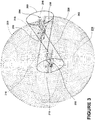
- Figure 3 illustrates alternative aircraft 202 and 204 according to a third embodiment of the invention.
- the third embodiment is similar to the second embodiment; therefore, like parts will be identified with like numerals increased by 100, with it being understood that the description of the like parts of the second embodiment applies to the third embodiment, unless otherwise noted.
- the aircraft 202 is illustrated as including multiple grid generators 210 that are configured to transmit relative navigation grids 220 that collectively form a field of transmission 214 that create two somewhat opposing hemispheres around the aircraft 202.
- the relative navigation grids 220 may also be more aligned such that the field of transmission 214 creates a sphere around the aircraft 202. In this manner the relative navigation grid may be emitted in such a manner that any blind spots relative to the emitting aircraft 202 are eliminated.
- the relative navigation grid 220 may be emitted from multiple locations on the emitting aircraft 202 and any number of grid generators may be used to create such a spherical field of transmission 214 around the aircraft 202 including that a single grid generator may be configured to transmit such a field of transmission around the aircraft 202.
- the information related to the relative positions of the aircraft may be broadcast between the aircraft.
- the reading aircraft may transmit the spatial relationship to the emitting aircraft and the emitting aircraft may adjust its position if necessary.
- the emitting aircraft 202 has been illustrated as including an optical data link 260, schematically illustrated as extending from the aircraft 202.
- the aircraft 204 has been illustrated as including an optical data link 262.
- the optical data links 260 and 262 may include any suitable communication having a certain range or field of transmission.
- the optical data links 260 and 262 may be capable of transmitting and receiving data from collaborating or cooperative aircraft that are suitably equipped.
- the aircraft 204 has been illustrated as including optical reflectors 250 and the aircraft 202 may include a detector module 216, which could be a separate module as illustrated or could be included in the grid generators 210. Alternatively, the aircraft 204 may include a detector module 216. As described above the aircraft 202 and 204 may determine their relative position. Once one of the two aircraft 202 and 204 knows the relative position between the two aircraft 202 and 204 this information may be transmitted via the optical data links 260 and 262 to the other of the aircraft and one or both of the aircraft may adjust their positions accordingly.
- the size and field of regard of the generated relative navigation grid may be tailored to mission and flight profile requirements. While all of the examples given so far have include two aircraft it will be understood that any number of aircraft may fly in formation and adjust their relative positions if they are so suitable equipped. If the multiple aircraft are equipped with optical data links the multiple aircraft may be capable of maintaining relative navigation with only one aircraft equipped with a grid generator. It is contemplated that in such an instance the reading aircraft may transmits the spatial relationship to the others of the multiple aircraft.
- Figure 4 illustrates a method 300 for two or more aircraft to fly in close proximately according to a predetermined formation without colliding according to one embodiment of the invention. Such a method may be used with any of the above described embodiments.
- the method 300 begins at 302 with emitting from one of the aircraft a relative navigation grid to define an emitting aircraft amongst the aircraft. Such emitting may include emitting the relative navigation grid in a direction where another aircraft should be in the predetermined formation.
- the direction may be at least one of forward and rearward along a direction of travel of the emitting aircraft.
- the direction may be an alternative direction including upwards, downwards, to one sides, or a combination of several directions.
- the spatial relationship between at least two of the aircraft based on the emitted relative navigation grid may then be calculated. This may be done by a processor on the reading aircraft.
- one of the aircraft may then determine if the spatial relationship conforms with the predetermined formation. If the spatial relationship conforms to the predetermined formation, the method may return to transmitting the relative navigation grid at 302 and the method may be repeated until it is determined that the spatial relationship of the aircraft does not conform to the predetermined formation.
- a relative position of at least one of the aircraft may be altered to position the aircraft in the predetermined formation. It will be understood that the emitting, calculating, determining, and altering may be repeated to maintain the aircraft in the predetermined formation during flight.
- the method becomes more complex when more than two aircraft are flying in formation and when those aircraft are equipped with any number and combination of emitters, detector modules, and reflectors to form any number and combination of emitting aircraft, deflecting aircraft and reading aircraft.
- the reading aircraft may be the same as the emitting aircraft, in the case of reflectance from another aircraft, or it can be a separate aircraft, or a combination of both. Further, the reading aircraft may be an aircraft other than the two aircraft, there may be multiple reading aircraft, multiple reflecting aircraft, and/or multiple emitting aircraft. By way of non-limiting example, in the case where there are more than two aircraft a reflection may be sent to another aircraft that is not the emitting aircraft, which may read the reflected relative navigation grid position and make the desired calculations and transmissions, etc.
- More than one of the multiple reading aircraft may calculate the spatial relationship data. It is contemplated that at least one of the multiple reading aircraft may determine the spatial relationship between a different two aircraft. Further, more than one of the multiple reading aircraft may transmit the spatial relationship data to the at least some of the other aircraft regardless of whether the grid information was received through reflectance or direct detection.
- Figure 5 illustrates a method 400 for flying multiple aircraft in a predetermined formation according to another embodiment of the invention.
- Possible formations may include but are not limited to, a V formation, a box formation, a ladder formation, a route formation, an echelon formation, and a wall formation.
- the sequence depicted is for illustrative purposes only and is not meant to limit the method 400 in any way. It may be understood that the portions of the method may proceed in a different logical order, additional or intervening portions may be included, or described portions of the method may be divided into multiple portions, or described portions of the method may be omitted without detracting from the described method.
- the method 400 begins at 402 with transmitting from one or more of the aircraft a relative navigation grid to define one or more emitting aircraft amongst the multiple aircraft. It will be understood that the relative navigation grid may be transmitted to aircraft that have reflectors and/or detector modules. At 404 the relative navigation grid position may be received by one or more reading aircraft through reflection and/or by directly reading the transmitted relative navigation grid. At 406, the spatial relationship between at least two of the aircraft based on the read relative navigation grid may then be calculated.
- such as spatial relationship may be transmitted via optical data links to other of the multiple aircraft.
- the position of the other aircraft may be received by other of the multiple aircraft.
- one of the aircraft having received the data link information may compute relative positions of at least some of the multiple aircraft based on such data link information. Such a computation may be done in a flight control computer or other processor of the aircraft.
- it may be determined if the spatial relationship conforms with the predetermined formation. This may also be done in a flight control computer or other processor of the aircraft and the determination assumes knowledge of the predetermined formation and the location of the grid generator in the formation.
- the method may return to transmitting the relative navigation grid at 402 and the method may be repeated until it is determined that the spatial relationship of the aircraft does not conform to the predetermined formation. If the spatial relationship does not conform to the predetermined formation, the method may proceed to 416. The determination may take into account both the relative position computed at 408 based on information received related to the relative navigation grid through a detector module and any additional relative positions computed at 412 based on information from the optical data links. In this manner the position of the aircraft may be determined relative to a number of multiple aircraft.
- one or more of the multiple aircraft may navigate to maintain the predetermined relative position. This may include the separation error of the aircraft from its predetermined position being sent at 418 to the autopilot of the aircraft such that the autopilot may adjust the location of the aircraft at 420.
- the use of autopilot in this manner may be more accurate and faster than human response by using available electrical signals for electronic control of the aircraft for purposes of flight coordination and avoiding collisions between aircraft.
- the above described embodiments provide for a number of benefits.
- the above described embodiments may allow for formation flying with much higher precision, much faster data rates, and lower observable relative navigation information at a lower cost than contemporary systems.
- the technical effect being that the embodiments described above may, for aircraft separated by approximately 100 feet, accurately and rapidly measure the 3-dimensional relative position of an adjacent aircraft to an accuracy of better than 1 inch and within 50 milliseconds.
- the embodiments described above may be used to make determinations in real time or near real time and the determinations may be carried out automatically and reliably without human intervention or constant maintenance in order to meet requirements of specific applications and to reduce system operation cost.
Landscapes
- Engineering & Computer Science (AREA)
- Aviation & Aerospace Engineering (AREA)
- Radar, Positioning & Navigation (AREA)
- Remote Sensing (AREA)
- Physics & Mathematics (AREA)
- General Physics & Mathematics (AREA)
- Automation & Control Theory (AREA)
- Traffic Control Systems (AREA)
- Optical Radar Systems And Details Thereof (AREA)
- Control Of Position, Course, Altitude, Or Attitude Of Moving Bodies (AREA)
Claims (15)
- Verfahren (300) zum Fliegen eines Luftfahrzeugs (2, 4, 102, 104, 202, 204) in einer vorbestimmten Formation, das Verfahren umfassend:Aussenden (302), von einem Luftfahrzeug (102, 202), eines relativen Navigationsgitters (120, 220) zum Definieren eines aussendenden Luftfahrzeugs (102, 202) unter den Luftfahrzeugen;Reflektieren, unter Benutzung von einem oder mehreren optischen Reflektoren (150, 250), die an einem anderen der Luftfahrzeuge (104, 204) enthalten sind, von mindestens einem Abschnitt des ausgesendeten relativen Navigationsgitters zurück zum aussendenden Luftfahrzeug (102, 202);Berechnen (304) einer räumlichen Beziehung zwischen den zwei Luftfahrzeugen auf Grundlage des reflektierten relativen Navigationsgitters (120, 220);Bestimmen (306), ob die räumliche Beziehung mit der vorbestimmten Formation konform ist; undÄndern (308) einer relativen Position von mindestens einem der Luftfahrzeuge zum Positionieren des Luftfahrzeugs in der vorbestimmten Formation, wenn die räumliche Beziehung nicht mit der vorbestimmten Formation konform ist.
- Verfahren nach Anspruch 1, weiter umfassend das Wiederholen des Aussendens, Berechnens, Bestimmens und Änderns zum Erhalten des Luftfahrzeugs in der vorbestimmten Formation.
- Verfahren nach einem der Ansprüche 1 oder 2, wobei das Aussenden weiter das Aussenden des relativen Navigationsgitters (20) in einer Richtung umfasst, in der ein anderes Luftfahrzeug (4) in der vorbestimmten Formation sein sollte.
- Verfahren nach Anspruch 3, wobei die Richtung mindestens eine von vorwärts und rückwärts entlang einer Flugrichtung des aussendenden Luftfahrzeugs (2) ist.
- Verfahren nach einem der vorstehenden Ansprüche, wobei das Aussenden weiter das Aussenden des relativen Navigationsgitters (220) in mindestens einen Sektor einer Hemisphäre relativ zum aussendenden Luftfahrzeug (202) umfasst.
- Verfahren nach einem der vorstehenden Ansprüche, wobei das Aussenden weiter das Aussenden des relativen Navigationsgitters (220) zum Eliminieren jeglicher toter Zonen relativ zum aussendenden Luftfahrzeug (202) umfasst.
- Verfahren nach einem der vorstehenden Ansprüche, wobei das Aussenden weiter das Aussenden des relativen Navigationsgitters (202) von mehreren Stellen des aussendenden Luftfahrzeugs (202) umfasst.
- Verfahren nach einem der vorstehenden Ansprüche, wobei das Berechnen (304) der räumlichen Beziehung durch einen Prozessor an Bord von mindestens einem der Luftfahrzeuge (2, 4) ausgeführt wird.
- Verfahren nach einem der vorstehenden Ansprüche, wobei mindestens eines der Luftfahrzeuge (4) ein lesendes Luftfahrzeug ist, das das ausgesendete relative Navigationsgitter (20) liest.
- Verfahren nach Anspruch 9, wobei das lesende Luftfahrzeug (4) die räumliche Beziehung auf Grundlage des Lesens des ausgesendeten relativen Navigationsgitters berechnet.
- Verfahren nach Anspruch 10, wobei das lesende Luftfahrzeug (4) die räumliche Beziehung an mindestens ein weiteres der Luftfahrzeuge überträgt.
- Verfahren nach einem der Ansprüche 9 bis 11, wobei das lesende Luftfahrzeug und das aussendende Luftfahrzeug dasselbe Luftfahrzeug (102) ist.
- Verfahren nach einem der Ansprüche 9 bis 11, wobei das lesende Luftfahrzeug und das aussendende Luftfahrzeug verschiedene Luftfahrzeuge sind.
- Verfahren nach Anspruch 13, wobei das lesende Luftfahrzeug das andere der zwei Luftfahrzeuge ist.
- Verfahren nach Anspruch 13, wobei das lesende Luftfahrzeug ein Luftfahrzeug ist, das ein anderes als die zwei Luftfahrzeuge ist.
Applications Claiming Priority (1)
| Application Number | Priority Date | Filing Date | Title |
|---|---|---|---|
| US13/405,718 US8463463B1 (en) | 2012-02-27 | 2012-02-27 | Methods for formation flying aided by a relative navigation system |
Publications (2)
| Publication Number | Publication Date |
|---|---|
| EP2631733A1 EP2631733A1 (de) | 2013-08-28 |
| EP2631733B1 true EP2631733B1 (de) | 2017-12-06 |
Family
ID=47749692
Family Applications (1)
| Application Number | Title | Priority Date | Filing Date |
|---|---|---|---|
| EP13156511.1A Active EP2631733B1 (de) | 2012-02-27 | 2013-02-25 | Verfahren zum Formationsfliegen mit einem relativen Navigationssystem |
Country Status (6)
| Country | Link |
|---|---|
| US (1) | US8463463B1 (de) |
| EP (1) | EP2631733B1 (de) |
| JP (1) | JP2013173523A (de) |
| CN (1) | CN103294063B (de) |
| BR (1) | BR102013003780A2 (de) |
| CA (1) | CA2806850C (de) |
Cited By (1)
| Publication number | Priority date | Publication date | Assignee | Title |
|---|---|---|---|---|
| CN108459612A (zh) * | 2017-02-21 | 2018-08-28 | 北京航空航天大学 | 基于人工势场法的无人机编队控制方法及装置 |
Families Citing this family (21)
| Publication number | Priority date | Publication date | Assignee | Title |
|---|---|---|---|---|
| US9766610B2 (en) | 2012-03-07 | 2017-09-19 | Rehco, Llc | Interactive application platform for a motorized toy entity and display |
| US9121709B2 (en) * | 2013-03-12 | 2015-09-01 | Ge Aviation Systems, Llc | Method of forming a grid defining a first relative reference frame |
| CN104548597B (zh) * | 2014-12-26 | 2018-06-01 | 北京像素软件科技股份有限公司 | 导航网格的自动生成方法和装置 |
| US9435635B1 (en) * | 2015-02-27 | 2016-09-06 | Ge Aviation Systems Llc | System and methods of detecting an intruding object in a relative navigation system |
| CN105242544B (zh) * | 2015-10-30 | 2017-11-14 | 山东科技大学 | 考虑随机扰动的非线性多无人机系统容错编队控制方法 |
| CN105629966B (zh) * | 2016-02-01 | 2019-05-21 | 东南大学 | 一种多层环绕编队包围的几何设计方法 |
| US10073454B2 (en) | 2016-03-17 | 2018-09-11 | Northrop Grumman Systems Corporation | Machine vision enabled swarm guidance technology |
| US10053218B2 (en) | 2016-03-31 | 2018-08-21 | General Electric Company | System and method for positioning an unmanned aerial vehicle |
| CN105974939B (zh) * | 2016-07-25 | 2018-12-28 | 天津远度科技有限公司 | 无人机编队阵型自动生成方法及装置 |
| US10068474B2 (en) * | 2016-10-02 | 2018-09-04 | Ge Aviation Systems Llc | Method and vehicle traffic control system |
| US9824599B1 (en) | 2016-10-02 | 2017-11-21 | Ge Aviation Systems Llc | Method and vehicle traffic control system |
| US20190004544A1 (en) * | 2017-06-29 | 2019-01-03 | Ge Aviation Systems, Llc | Method for flying at least two aircraft |
| US11508255B2 (en) | 2018-04-27 | 2022-11-22 | Red Six Aerospace Inc. | Methods, systems, apparatuses and devices for facilitating provisioning of a virtual experience |
| US11436932B2 (en) | 2018-04-27 | 2022-09-06 | Red Six Aerospace Inc. | Methods and systems to allow real pilots in real aircraft using augmented and virtual reality to meet in a virtual piece of airspace |
| US11002960B2 (en) | 2019-02-21 | 2021-05-11 | Red Six Aerospace Inc. | Methods, systems, apparatuses, and devices for facilitating provisioning of a virtual experience |
| US11869388B2 (en) | 2018-04-27 | 2024-01-09 | Red Six Aerospace Inc. | Augmented reality for vehicle operations |
| US11887495B2 (en) | 2018-04-27 | 2024-01-30 | Red Six Aerospace Inc. | Augmented reality for vehicle operations |
| CN111459161B (zh) * | 2020-04-03 | 2021-07-06 | 北京理工大学 | 一种多机器人系统人为干预控制方法 |
| US12165526B1 (en) | 2020-12-22 | 2024-12-10 | Rockwell Collins, Inc. | System and method for providing maneuvering behaviors to a vehicle using maneuver primitives |
| FR3136866A1 (fr) * | 2022-06-15 | 2023-12-22 | Airbus | Procede de gestion de la position longitudinale d’un aeronef suiveur par rapport a un aeronef meneur |
| CN116030664A (zh) * | 2023-03-28 | 2023-04-28 | 中科星图智慧科技有限公司 | 基于网格的低空飞行碰撞预警方法、装置、设备及介质 |
Family Cites Families (31)
| Publication number | Priority date | Publication date | Assignee | Title |
|---|---|---|---|---|
| DE663795C (de) * | 1933-08-12 | 1938-08-13 | Siemens & Halske Akt Ges | Einrichtung zur Aufrechterhaltung einer gewuenschten Gruppierung von Fahrzeugen, insbesondere Luftfahrzeugen |
| US3553695A (en) * | 1967-09-29 | 1971-01-05 | Bendix Corp | Helicopter airborne beacon system for use in formation flying |
| US3778835A (en) * | 1971-04-20 | 1973-12-11 | Computer Sciences Corp | Bearing detection system |
| US4232313A (en) * | 1972-09-22 | 1980-11-04 | The United States Of America As Represented By The Secretary Of The Navy | Tactical nagivation and communication system |
| JPS5842431B2 (ja) | 1975-12-29 | 1983-09-20 | 富士重工業株式会社 | 飛翔体の光ビ−ム誘導装置 |
| GB1536547A (en) * | 1976-08-10 | 1978-12-20 | Ferranti Ltd | Aircraft guidance systems |
| US5326052A (en) | 1991-10-02 | 1994-07-05 | Enig Associates, Inc. | Controllable hose-and-drogue in-flight refueling system |
| US5465142A (en) | 1993-04-30 | 1995-11-07 | Northrop Grumman Corporation | Obstacle avoidance system for helicopters and other aircraft |
| JPH1045099A (ja) * | 1996-07-31 | 1998-02-17 | Mitsubishi Heavy Ind Ltd | 自動編隊飛行制御装置 |
| US5838262A (en) | 1996-12-19 | 1998-11-17 | Sikorsky Aircraft Corporation | Aircraft virtual image display system and method for providing a real-time perspective threat coverage display |
| IL130158A0 (en) | 1999-05-27 | 2000-06-01 | Kalisch Gad | Bordered flying tool |
| AU1186301A (en) * | 1999-06-21 | 2001-01-22 | Lockheed Martin Corporation | System and method for locating and maintaining objects in free space |
| US7010398B2 (en) | 2001-10-11 | 2006-03-07 | The Boeing Company | Control system providing perspective flight guidance |
| US6641082B2 (en) * | 2002-04-01 | 2003-11-04 | Lockheed Martin Corporation | Aircraft ferrying system and method thereof |
| US6963795B2 (en) | 2002-07-16 | 2005-11-08 | Honeywell Interntaional Inc. | Vehicle position keeping system |
| US6669145B1 (en) | 2002-12-30 | 2003-12-30 | The Boeing Company | Apparatus, method and system for fluid-motion-powered modulation of a retroreflector for remote position sensing |
| US7343232B2 (en) | 2003-06-20 | 2008-03-11 | Geneva Aerospace | Vehicle control system including related methods and components |
| US6926233B1 (en) * | 2004-02-21 | 2005-08-09 | Corcoran, Iii James John | Automatic formation flight control system (AFFCS)—a system for automatic formation flight control of vehicles not limited to aircraft, helicopters, or space platforms |
| US7818127B1 (en) | 2004-06-18 | 2010-10-19 | Geneva Aerospace, Inc. | Collision avoidance for vehicle control systems |
| US7272472B1 (en) * | 2004-07-15 | 2007-09-18 | Rockwell Collins, Inc. | System and method for improving aircraft formation flying accuracy and integrity |
| JP4424190B2 (ja) | 2004-12-14 | 2010-03-03 | 三菱電機株式会社 | 編隊飛行衛星の軌道制御装置 |
| US7701592B2 (en) | 2004-12-17 | 2010-04-20 | The Boeing Company | Method and apparatus for combining a targetless optical measurement function and optical projection of information |
| US7681839B2 (en) | 2005-02-25 | 2010-03-23 | Smiths Aerospace Llc | Optical tracking system for refueling |
| US7789339B2 (en) * | 2005-07-07 | 2010-09-07 | Sommer Geoffrey S | Modular articulated-wing aircraft |
| US7357352B2 (en) * | 2005-11-09 | 2008-04-15 | The Boeing Company | Air vehicle assembly and an associated control system and method |
| IL181889A (en) | 2007-03-13 | 2010-11-30 | Israel Aerospace Ind Ltd | Method and system for providing a known reference point for an airborne imaging platform |
| US8061646B2 (en) * | 2007-09-14 | 2011-11-22 | Aurora Flight Sciences Corporation | Wing tip docking system for aircraft |
| US7966872B2 (en) * | 2008-07-23 | 2011-06-28 | The Boeing Company | In-flight testing kits and methods for evaluating proposed aerodynamic structures for aircraft |
| US8400511B2 (en) | 2009-12-04 | 2013-03-19 | Lockheed Martin Corporation | Optical detection and ranging sensor system for sense and avoid, and related methods |
| US8386096B2 (en) | 2009-12-22 | 2013-02-26 | General Electric Company | Relative navigation system |
| US8326523B2 (en) * | 2009-12-22 | 2012-12-04 | General Electric Company | Method of determining range |
-
2012
- 2012-02-27 US US13/405,718 patent/US8463463B1/en active Active
-
2013
- 2013-02-19 BR BR102013003780-0A patent/BR102013003780A2/pt active Search and Examination
- 2013-02-21 CA CA2806850A patent/CA2806850C/en not_active Expired - Fee Related
- 2013-02-21 JP JP2013031616A patent/JP2013173523A/ja active Pending
- 2013-02-25 EP EP13156511.1A patent/EP2631733B1/de active Active
- 2013-02-27 CN CN201310061274.7A patent/CN103294063B/zh active Active
Non-Patent Citations (1)
| Title |
|---|
| None * |
Cited By (1)
| Publication number | Priority date | Publication date | Assignee | Title |
|---|---|---|---|---|
| CN108459612A (zh) * | 2017-02-21 | 2018-08-28 | 北京航空航天大学 | 基于人工势场法的无人机编队控制方法及装置 |
Also Published As
| Publication number | Publication date |
|---|---|
| EP2631733A1 (de) | 2013-08-28 |
| CA2806850A1 (en) | 2013-08-27 |
| US8463463B1 (en) | 2013-06-11 |
| CA2806850C (en) | 2020-04-21 |
| CN103294063A (zh) | 2013-09-11 |
| CN103294063B (zh) | 2018-05-15 |
| BR102013003780A2 (pt) | 2014-04-29 |
| JP2013173523A (ja) | 2013-09-05 |
Similar Documents
| Publication | Publication Date | Title |
|---|---|---|
| EP2631733B1 (de) | Verfahren zum Formationsfliegen mit einem relativen Navigationssystem | |
| EP3062123B1 (de) | System und verfahren zur detektion eines eindringenden objekts in einem relativen navigationssystem | |
| EP3422134A1 (de) | Verfahren zum fliegen von mindestens zwei flugzeugen | |
| EP2589930B1 (de) | Verfahren zur Anpassung eines relativen Navigationssystems | |
| US10571224B2 (en) | Systems, methods and computer-readable media for improving platform guidance or navigation using uniquely coded signals | |
| US10131446B1 (en) | Addressing multiple time around (MTA) ambiguities, particularly for lidar systems, and particularly for autonomous aircraft | |
| EP2339296B1 (de) | Verfahren zur Bereichsbestimmung | |
| EP2339295B1 (de) | Relatives Navigationssystem und Verfahren dafür | |
| CA2921261C (en) | System and methods for providing situational awareness information for a relative navigation system | |
| EP2703777B1 (de) | System und Verfahren zur Benutzung mehrerer Sensoren | |
| WO2017168423A1 (en) | System and method for autonomous guidance of vehicles | |
| US20170370678A1 (en) | Systems, Methods and Computer-Readable Media for Improving Platform Guidance or Navigation Using Uniquely Coded Signals | |
| JP2025537486A (ja) | 物体の相対位置データの決定 |
Legal Events
| Date | Code | Title | Description |
|---|---|---|---|
| PUAI | Public reference made under article 153(3) epc to a published international application that has entered the european phase |
Free format text: ORIGINAL CODE: 0009012 |
|
| AK | Designated contracting states |
Kind code of ref document: A1 Designated state(s): AL AT BE BG CH CY CZ DE DK EE ES FI FR GB GR HR HU IE IS IT LI LT LU LV MC MK MT NL NO PL PT RO RS SE SI SK SM TR |
|
| AX | Request for extension of the european patent |
Extension state: BA ME |
|
| 17P | Request for examination filed |
Effective date: 20140228 |
|
| RBV | Designated contracting states (corrected) |
Designated state(s): AL AT BE BG CH CY CZ DE DK EE ES FI FR GB GR HR HU IE IS IT LI LT LU LV MC MK MT NL NO PL PT RO RS SE SI SK SM TR |
|
| GRAP | Despatch of communication of intention to grant a patent |
Free format text: ORIGINAL CODE: EPIDOSNIGR1 |
|
| RIC1 | Information provided on ipc code assigned before grant |
Ipc: G05D 1/10 20060101AFI20170714BHEP |
|
| INTG | Intention to grant announced |
Effective date: 20170807 |
|
| GRAS | Grant fee paid |
Free format text: ORIGINAL CODE: EPIDOSNIGR3 |
|
| GRAA | (expected) grant |
Free format text: ORIGINAL CODE: 0009210 |
|
| AK | Designated contracting states |
Kind code of ref document: B1 Designated state(s): AL AT BE BG CH CY CZ DE DK EE ES FI FR GB GR HR HU IE IS IT LI LT LU LV MC MK MT NL NO PL PT RO RS SE SI SK SM TR |
|
| REG | Reference to a national code |
Ref country code: GB Ref legal event code: FG4D |
|
| REG | Reference to a national code |
Ref country code: AT Ref legal event code: REF Ref document number: 952931 Country of ref document: AT Kind code of ref document: T Effective date: 20171215 Ref country code: CH Ref legal event code: EP |
|
| REG | Reference to a national code |
Ref country code: IE Ref legal event code: FG4D |
|
| REG | Reference to a national code |
Ref country code: DE Ref legal event code: R096 Ref document number: 602013030301 Country of ref document: DE |
|
| REG | Reference to a national code |
Ref country code: FR Ref legal event code: PLFP Year of fee payment: 6 |
|
| REG | Reference to a national code |
Ref country code: NL Ref legal event code: MP Effective date: 20171206 |
|
| REG | Reference to a national code |
Ref country code: LT Ref legal event code: MG4D |
|
| PG25 | Lapsed in a contracting state [announced via postgrant information from national office to epo] |
Ref country code: FI Free format text: LAPSE BECAUSE OF FAILURE TO SUBMIT A TRANSLATION OF THE DESCRIPTION OR TO PAY THE FEE WITHIN THE PRESCRIBED TIME-LIMIT Effective date: 20171206 Ref country code: ES Free format text: LAPSE BECAUSE OF FAILURE TO SUBMIT A TRANSLATION OF THE DESCRIPTION OR TO PAY THE FEE WITHIN THE PRESCRIBED TIME-LIMIT Effective date: 20171206 Ref country code: LT Free format text: LAPSE BECAUSE OF FAILURE TO SUBMIT A TRANSLATION OF THE DESCRIPTION OR TO PAY THE FEE WITHIN THE PRESCRIBED TIME-LIMIT Effective date: 20171206 Ref country code: NO Free format text: LAPSE BECAUSE OF FAILURE TO SUBMIT A TRANSLATION OF THE DESCRIPTION OR TO PAY THE FEE WITHIN THE PRESCRIBED TIME-LIMIT Effective date: 20180306 Ref country code: SE Free format text: LAPSE BECAUSE OF FAILURE TO SUBMIT A TRANSLATION OF THE DESCRIPTION OR TO PAY THE FEE WITHIN THE PRESCRIBED TIME-LIMIT Effective date: 20171206 |
|
| REG | Reference to a national code |
Ref country code: AT Ref legal event code: MK05 Ref document number: 952931 Country of ref document: AT Kind code of ref document: T Effective date: 20171206 |
|
| PG25 | Lapsed in a contracting state [announced via postgrant information from national office to epo] |
Ref country code: LV Free format text: LAPSE BECAUSE OF FAILURE TO SUBMIT A TRANSLATION OF THE DESCRIPTION OR TO PAY THE FEE WITHIN THE PRESCRIBED TIME-LIMIT Effective date: 20171206 Ref country code: BG Free format text: LAPSE BECAUSE OF FAILURE TO SUBMIT A TRANSLATION OF THE DESCRIPTION OR TO PAY THE FEE WITHIN THE PRESCRIBED TIME-LIMIT Effective date: 20180306 Ref country code: HR Free format text: LAPSE BECAUSE OF FAILURE TO SUBMIT A TRANSLATION OF THE DESCRIPTION OR TO PAY THE FEE WITHIN THE PRESCRIBED TIME-LIMIT Effective date: 20171206 Ref country code: RS Free format text: LAPSE BECAUSE OF FAILURE TO SUBMIT A TRANSLATION OF THE DESCRIPTION OR TO PAY THE FEE WITHIN THE PRESCRIBED TIME-LIMIT Effective date: 20171206 Ref country code: GR Free format text: LAPSE BECAUSE OF FAILURE TO SUBMIT A TRANSLATION OF THE DESCRIPTION OR TO PAY THE FEE WITHIN THE PRESCRIBED TIME-LIMIT Effective date: 20180307 |
|
| PG25 | Lapsed in a contracting state [announced via postgrant information from national office to epo] |
Ref country code: NL Free format text: LAPSE BECAUSE OF FAILURE TO SUBMIT A TRANSLATION OF THE DESCRIPTION OR TO PAY THE FEE WITHIN THE PRESCRIBED TIME-LIMIT Effective date: 20171206 |
|
| PG25 | Lapsed in a contracting state [announced via postgrant information from national office to epo] |
Ref country code: EE Free format text: LAPSE BECAUSE OF FAILURE TO SUBMIT A TRANSLATION OF THE DESCRIPTION OR TO PAY THE FEE WITHIN THE PRESCRIBED TIME-LIMIT Effective date: 20171206 Ref country code: CZ Free format text: LAPSE BECAUSE OF FAILURE TO SUBMIT A TRANSLATION OF THE DESCRIPTION OR TO PAY THE FEE WITHIN THE PRESCRIBED TIME-LIMIT Effective date: 20171206 Ref country code: SK Free format text: LAPSE BECAUSE OF FAILURE TO SUBMIT A TRANSLATION OF THE DESCRIPTION OR TO PAY THE FEE WITHIN THE PRESCRIBED TIME-LIMIT Effective date: 20171206 |
|
| PG25 | Lapsed in a contracting state [announced via postgrant information from national office to epo] |
Ref country code: AT Free format text: LAPSE BECAUSE OF FAILURE TO SUBMIT A TRANSLATION OF THE DESCRIPTION OR TO PAY THE FEE WITHIN THE PRESCRIBED TIME-LIMIT Effective date: 20171206 Ref country code: SM Free format text: LAPSE BECAUSE OF FAILURE TO SUBMIT A TRANSLATION OF THE DESCRIPTION OR TO PAY THE FEE WITHIN THE PRESCRIBED TIME-LIMIT Effective date: 20171206 Ref country code: IT Free format text: LAPSE BECAUSE OF FAILURE TO SUBMIT A TRANSLATION OF THE DESCRIPTION OR TO PAY THE FEE WITHIN THE PRESCRIBED TIME-LIMIT Effective date: 20171206 Ref country code: RO Free format text: LAPSE BECAUSE OF FAILURE TO SUBMIT A TRANSLATION OF THE DESCRIPTION OR TO PAY THE FEE WITHIN THE PRESCRIBED TIME-LIMIT Effective date: 20171206 Ref country code: PL Free format text: LAPSE BECAUSE OF FAILURE TO SUBMIT A TRANSLATION OF THE DESCRIPTION OR TO PAY THE FEE WITHIN THE PRESCRIBED TIME-LIMIT Effective date: 20171206 |
|
| REG | Reference to a national code |
Ref country code: DE Ref legal event code: R097 Ref document number: 602013030301 Country of ref document: DE |
|
| REG | Reference to a national code |
Ref country code: CH Ref legal event code: PL |
|
| PG25 | Lapsed in a contracting state [announced via postgrant information from national office to epo] |
Ref country code: MC Free format text: LAPSE BECAUSE OF FAILURE TO SUBMIT A TRANSLATION OF THE DESCRIPTION OR TO PAY THE FEE WITHIN THE PRESCRIBED TIME-LIMIT Effective date: 20171206 |
|
| PLBE | No opposition filed within time limit |
Free format text: ORIGINAL CODE: 0009261 |
|
| STAA | Information on the status of an ep patent application or granted ep patent |
Free format text: STATUS: NO OPPOSITION FILED WITHIN TIME LIMIT |
|
| 26N | No opposition filed |
Effective date: 20180907 |
|
| REG | Reference to a national code |
Ref country code: IE Ref legal event code: MM4A |
|
| REG | Reference to a national code |
Ref country code: BE Ref legal event code: MM Effective date: 20180228 |
|
| PG25 | Lapsed in a contracting state [announced via postgrant information from national office to epo] |
Ref country code: LU Free format text: LAPSE BECAUSE OF NON-PAYMENT OF DUE FEES Effective date: 20180225 Ref country code: DK Free format text: LAPSE BECAUSE OF FAILURE TO SUBMIT A TRANSLATION OF THE DESCRIPTION OR TO PAY THE FEE WITHIN THE PRESCRIBED TIME-LIMIT Effective date: 20171206 Ref country code: LI Free format text: LAPSE BECAUSE OF NON-PAYMENT OF DUE FEES Effective date: 20180228 Ref country code: SI Free format text: LAPSE BECAUSE OF FAILURE TO SUBMIT A TRANSLATION OF THE DESCRIPTION OR TO PAY THE FEE WITHIN THE PRESCRIBED TIME-LIMIT Effective date: 20171206 Ref country code: CH Free format text: LAPSE BECAUSE OF NON-PAYMENT OF DUE FEES Effective date: 20180228 |
|
| PG25 | Lapsed in a contracting state [announced via postgrant information from national office to epo] |
Ref country code: IE Free format text: LAPSE BECAUSE OF NON-PAYMENT OF DUE FEES Effective date: 20180225 |
|
| PG25 | Lapsed in a contracting state [announced via postgrant information from national office to epo] |
Ref country code: BE Free format text: LAPSE BECAUSE OF NON-PAYMENT OF DUE FEES Effective date: 20180228 |
|
| PG25 | Lapsed in a contracting state [announced via postgrant information from national office to epo] |
Ref country code: MT Free format text: LAPSE BECAUSE OF NON-PAYMENT OF DUE FEES Effective date: 20180225 |
|
| PG25 | Lapsed in a contracting state [announced via postgrant information from national office to epo] |
Ref country code: TR Free format text: LAPSE BECAUSE OF FAILURE TO SUBMIT A TRANSLATION OF THE DESCRIPTION OR TO PAY THE FEE WITHIN THE PRESCRIBED TIME-LIMIT Effective date: 20171206 |
|
| PG25 | Lapsed in a contracting state [announced via postgrant information from national office to epo] |
Ref country code: HU Free format text: LAPSE BECAUSE OF FAILURE TO SUBMIT A TRANSLATION OF THE DESCRIPTION OR TO PAY THE FEE WITHIN THE PRESCRIBED TIME-LIMIT; INVALID AB INITIO Effective date: 20130225 Ref country code: PT Free format text: LAPSE BECAUSE OF FAILURE TO SUBMIT A TRANSLATION OF THE DESCRIPTION OR TO PAY THE FEE WITHIN THE PRESCRIBED TIME-LIMIT Effective date: 20171206 |
|
| PG25 | Lapsed in a contracting state [announced via postgrant information from national office to epo] |
Ref country code: MK Free format text: LAPSE BECAUSE OF NON-PAYMENT OF DUE FEES Effective date: 20171206 Ref country code: CY Free format text: LAPSE BECAUSE OF FAILURE TO SUBMIT A TRANSLATION OF THE DESCRIPTION OR TO PAY THE FEE WITHIN THE PRESCRIBED TIME-LIMIT Effective date: 20171206 |
|
| PG25 | Lapsed in a contracting state [announced via postgrant information from national office to epo] |
Ref country code: AL Free format text: LAPSE BECAUSE OF FAILURE TO SUBMIT A TRANSLATION OF THE DESCRIPTION OR TO PAY THE FEE WITHIN THE PRESCRIBED TIME-LIMIT Effective date: 20171206 Ref country code: IS Free format text: LAPSE BECAUSE OF FAILURE TO SUBMIT A TRANSLATION OF THE DESCRIPTION OR TO PAY THE FEE WITHIN THE PRESCRIBED TIME-LIMIT Effective date: 20180406 |
|
| P01 | Opt-out of the competence of the unified patent court (upc) registered |
Effective date: 20230414 |
|
| REG | Reference to a national code |
Ref country code: DE Ref legal event code: R079 Ref document number: 602013030301 Country of ref document: DE Free format text: PREVIOUS MAIN CLASS: G05D0001100000 Ipc: G05D0001460000 |
|
| PGFP | Annual fee paid to national office [announced via postgrant information from national office to epo] |
Ref country code: GB Payment date: 20260122 Year of fee payment: 14 |
|
| PGFP | Annual fee paid to national office [announced via postgrant information from national office to epo] |
Ref country code: DE Payment date: 20260121 Year of fee payment: 14 |
|
| PGFP | Annual fee paid to national office [announced via postgrant information from national office to epo] |
Ref country code: FR Payment date: 20260121 Year of fee payment: 14 |