EP2631810A1 - Procédé d'attribution d'adresses de participants et système périphérique modulaire de la technique d'automatisation - Google Patents
Procédé d'attribution d'adresses de participants et système périphérique modulaire de la technique d'automatisation Download PDFInfo
- Publication number
- EP2631810A1 EP2631810A1 EP12156861.2A EP12156861A EP2631810A1 EP 2631810 A1 EP2631810 A1 EP 2631810A1 EP 12156861 A EP12156861 A EP 12156861A EP 2631810 A1 EP2631810 A1 EP 2631810A1
- Authority
- EP
- European Patent Office
- Prior art keywords
- subscriber
- control module
- address
- switching means
- participants
- Prior art date
- Legal status (The legal status is an assumption and is not a legal conclusion. Google has not performed a legal analysis and makes no representation as to the accuracy of the status listed.)
- Granted
Links
Images


Classifications
-
- G—PHYSICS
- G06—COMPUTING OR CALCULATING; COUNTING
- G06F—ELECTRIC DIGITAL DATA PROCESSING
- G06F13/00—Interconnection of, or transfer of information or other signals between, memories, input/output devices or central processing units
- G06F13/38—Information transfer, e.g. on bus
- G06F13/42—Bus transfer protocol, e.g. handshake; Synchronisation
- G06F13/4247—Bus transfer protocol, e.g. handshake; Synchronisation on a daisy chain bus
-
- G—PHYSICS
- G06—COMPUTING OR CALCULATING; COUNTING
- G06F—ELECTRIC DIGITAL DATA PROCESSING
- G06F13/00—Interconnection of, or transfer of information or other signals between, memories, input/output devices or central processing units
- G06F13/38—Information transfer, e.g. on bus
- G06F13/40—Bus structure
- G06F13/4004—Coupling between buses
Definitions
- the invention relates to a method for allocating subscriber addresses to subscribers in a modular peripheral system of automation technology, wherein the peripheral system comprises a control module and a plurality of subscribers, the subscribers are connected to the control module such that a first subscriber is connected to the control module and other subscribers the control module is a starting point for a line structure of the concatenated interconnected participants, wherein the line structure comprises a first longitudinal branch and a second longitudinal branch and in a participant a first switching means in first longitudinal branch and a second switching means in the second longitudinal branch is first opened and operated at a later time for closing a chained communication path.
- a bus master communicates with various peripheral modules, which can each be parameterized as a slave, via a bus system.
- the peripheral modules may be, for example, digital inputs, digital outputs, analog I / O.
- the bus master can be embodied as an automation device in the form of a programmable logic controller or as an interface module, which represents an interface between a programmable logic controller and the peripheral modules, usually referred to as distributed peripherals.
- the I / O modules receive a unique address.
- the object is achieved in that, for extending the line structure to a tree structure, a connection element is switched into the chained communication path, wherein the connection element connects the first longitudinal branch and separates the second longitudinal branch in such a way that switching on another participant is possible for addressing a further subordinate line structure to the Anschaltelement, for addressing from the control module an address request is sent and by means arranged in the participants third switching means and a fourth switching means, which are controlled via a switching command such that when existing power-on first the Subscribers are addressed in the subordinate line structure.
- connection element in particular designed as a T-piece
- the subscribers are further developed in such a way that, in addition to the already known first and second second switching means have further switching means, namely a third switching means and a fourth switching means.
- the control module Via control commands such as switching commands, the control module, which is usually designed as a bus master, bring the switching means in the participants depending on the method step in defined positions.
- a development of the method provides that the third switching element is operated in a first shunt branch in such a way that, in an initial state, the third switching element selects and transmits response messages to the control module.
- This is advantageous because the subscribers in the first longitudinal branch and the second longitudinal branch are connected in such a way that a communication path should always be ensured back to the control module. That means; If, for example, a first subscriber is connected to the control module and an interface element is connected between the first user and a third user, to which in turn a second user is connected, then the second and third participants are followers of the first user. If the first subscriber has already successfully received an address and switched through the longitudinal branches with his first and second switching means, an address request can be sent to the second subscriber via the connecting element.
- the reply message would be returned from the second subscriber via the connection element to the third subscriber and from the third subscriber via the connection element via the first Participants get to the control board.
- the third switching means in the first shunt branch is operated in such a way that this positive response, which is directed to the control module, is transmitted.
- the automatic address allocation is further improved if the fourth switching means is operated in a second shunt branch such that in the event that no response message is sent to an address request in a predetermined time, the second shunt branch is closed and thus the end of the respective to the Anschaltelement connected subordinate lines marked and on the other a new communication path for address requests to the other participants in the parent Linen is switched.
- the automatic address assignment is further simplified if, starting from the control module, the address request is sent as a communication message via a bus formed by the longitudinal branches bus, the address request as a request parameter has a default address and an address to be assigned, further checked in the subscriber via a receiving unit is, whether an address value stored in it with the default address matches and for the case of a match, the stored address value is changed to the address to be assigned.
- the subscriber will generate a response message for the control module via a transmission unit and send it back to the control module, the control module being operated in such a way that it sends a first switching command to the subscriber in the case of a positive response message from the subscriber, the subscriber thus is operated by the first switching command, the first switching means and the second switching means are operated in a closed state and the third switching means is operated in an open state.
- control module will again send an address request to the other participants and in the event that no reply message to an address request in a given time , a second switching command is issued by the control assembly, wherein a single participant is configured to close the second shunt branch with the fourth switching means due to the second switching command, whereby on the one hand the end of the respective connected to the starting element subordinate line is marked and on the other new communication path for address requests to the other participants in the parent line is switched.
- a monitoring means is operated in the control module in such a way that the communication of the subscribers is monitored via the communication path and, in the event that a subscriber does not send a sign of life within a given time, all the subscribers are reset to an initial state.
- a modular peripheral system of automation technology comprising a control module and a plurality of subscribers, wherein the modular peripheral system is operated with the aforementioned method.
- the modular peripheral system of automation technology comprises a control module and a plurality of subscribers, wherein a first subscriber is in communication with the control module and links further subscribers
- the control module forms a starting point for a line structure of the concatenated interconnected participants
- the line structure has a first longitudinal branch and a second longitudinal branch
- a participant is in each case a first switching means arranged in the first longitudinal branch and a second switching means in the second longitudinal branch
- the control unit is configured to issue a first switching command
- the respective participant is configured by means of the first switching command, the first switching means and the second switching means from an open state to a closed state to offset the line structure to a tree structure
- a communication path is arranged in the connection means
- the connection element is designed connect the first longitudinal branch through and separate the second longitudinal branch and it is another participant for a further subordinate line structure connected to the Anschaltelement
- the control module is designed to address the subscriber configured to send an address request and further it is configured depending on a
- control module for controlling the switching means arranged in the subscribers, wherein the switching means can also be referred to as a communication path switch
- the switching means can also be referred to as a communication path switch
- this solution is more cost-effective, as passive components can be used to build the tree structure and non-expensive switch devices must be used.
- no unique IP addresses in the respective participants or in the peripheral device must be programmed.
- the third switching element is arranged in a first transverse branch and configured in an initial state to select and transmit response messages to the control module, wherein the initial state refers to a time before an address is assigned to a subscriber.
- the fourth switching means is arranged in a second shunt branch and the control module configured in the event that no response message to an address request in a given time to issue the second switching command, wherein a single participant is configured to the second shunt command the second shunt branch with to close the fourth switching means, whereby on the one hand one end of the respective connected to the Anschaltelement subordinate line is marked and on the other a new communication path for address requests to the other participants in the parent line is switched.
- control module is configured to send the address request as a communication message via a bus system formed by the longitudinal branches, wherein the address request has a default address and an address to be assigned as request parameters, wherein a receiving unit is furthermore arranged in the subscriber which checks whether an address value stored in it matches the standard address and in the event of a match, the stored address value is changed to the address to be assigned.
- a transmitting unit is arranged in each case in a subscriber, wherein the subscriber generates response message for the control module via the transmitting unit and sends it back to the control module, wherein the control module is designed such that it is at a positive Reply message of the subscriber sends the first switching command to the subscriber, wherein the subscriber is operated such that the first switching means and the second switching means are operated in a closed state by the first switching command and the third switching means is operated in an open state.
- a monitoring means is arranged and configured in the control module to monitor the communication and, in the event of a communication error, to send a reset switching command for resetting the subscribers to a default state.
- a subscriber may have his own subscriber monitoring means for resetting himself.
- FIG. 1 is a modular peripheral system 100 of automation technology, comprising a control module 10 and several participants 1, ..., 8 shown.
- a first subscriber 1 is connected directly to the control module 10 in such a way that a TX transmit port of the control module 10 is connected to an RX receive port of the first subscriber 1 and furthermore an RX receive port of the control module 10 with a TX transmit port of the first subscriber 1 connected is.
- the control module 10 forms a starting point A for a line structure 101, which may be referred to as a main line structure. Starting from this starting point A, the subscribers 1,..., 8 are interconnected to the control module 10.
- this device provides the possibility of deviating from a conventional line structure and, for example, to extend a backplane topology to a tree topology, form according to FIG. 1 a first subscriber 1, a third subscriber 3 and an eighth subscriber 8 the line structure 101 (main structure or superordinate line structure).
- a second participant 2 By arranging a first connection element 31 between the first participant 1 and the third participant 3, a second participant 2 can be connected to the higher-order line structure 101 and thereby a subordinate line structure 102 can be formed via the second participant 2.
- the first connection element 31 is designed as a T-piece and can be designed, for example, as an assembly which is plugged onto an existing longitudinally extending backplane bus of an automation device.
- the first connection element 31 has essentially three connection points.
- the first longitudinal branch 21 and the second longitudinal branch 22 of a preceding participant are received, at a second connection point the first longitudinal branch 21 and the second longitudinal branch 22 are forwarded to a subsequent participant of the higher-order line structure 101 and to a third connection point Connection point has been created the opportunity to loop the second party 2 in the parent line structure 101, wherein the second participant 2 in turn forms a subordinate line structure 102.
- the first connection element 31 is arranged between the first participant 1 and the third participant 3 and configured to connect the first longitudinal branch 21 and to separate the second longitudinal branch 22, whereby the second participant 2 is another can form subordinate line structure 102.
- a second starting element 32 is arranged between the third participant 3 and an eighth participant 8.
- the second connection element 32 ensures that the higher-order line structure 101 is broken up again between the third participant 3 and the eighth participant 8, and a further subordinate line structure 103 is opened via a fourth participant 4 connected to the second connection element 32.
- the fourth participant 4 of the predecessor participants to a subsequent fifth participant 5 wherein the extended line structure 103 is completed with a seventh participant 7.
- a third switch-on element 33 is arranged between the fifth participant 5 and the seventh participant 7.
- the third connection element 33 makes it possible to construct a further subordinate line structure 104.
- This subordinate line structure 104 has a sixth element 6.
- the second subscriber 2 in the subordinate line structure 102 forms a first end E1, the sixth subscriber 6 in the subordinate line structure 104 a second end E2, the seventh subscriber 7 in the subordinate line structure 103, a third end E3, and finally, the eighth subscriber 8 in the parent line structure 101 forms a fourth end E4, which extends from a conventional line structure to a tree-structured backplane topology.
- the first participant 1 to eighth participant 8 are identical.
- Each subscriber has a first switching means S1, a second switching means S2, a third switching means S3 and a fourth switching means S4.
- the first switching means S1 is arranged in the first longitudinal branch 21 and the second switching means S2 is arranged in the second longitudinal branch 22.
- the third switching means S3 is arranged in a first transverse branch 23 and the fourth switching means S4 is arranged in a second transverse branch 24.
- Each subscriber 1,..., 8 has on the input side and on the output side each one TX transmit port and one RX receive port each.
- the first switching means S1 connects the input TX transmit port to the output RX receive port
- the second switch S2 connects the RX receive port located on the input side to the TX transmit port arranged on the output side.
- This interconnected connection of the TX transmission port of a predecessor module with the RX reception port of a successor module or the connection of the RX reception port of a predecessor module to the X-end port of a successor module forms a concatenated communication path through the entire bus topology of the modular peripheral system 100.
- the control module 10 For transmitting switching commands, such as a first switching command and a second switching command, the control module 10 has a transmitter 10a and a receiver 10b.
- the transmitter 10a is connected to a TX transmit port of the control board 10 and thus can send switching commands to the peripheral system 100 via the daisy chain described above.
- the receiver 10b is connected to an RX receive port of the control module 10 and can thus likewise receive response messages from the subscribers 1,..., 8 via the aforementioned chaining.
- the control module 10 has a monitoring means 11.
- the subscribers 1,..., 8 each have a subscriber monitoring means 12, with which the subscribers 1,..., 8 can additionally reset themselves, wherein the subscriber monitoring means 12 is configured such that after a successful address assignment the communication to this Participant is monitored and if he no longer receives requests within a given time, the participant resets himself.
- the subscribers 1,..., 8 in turn have a receiving unit 40 and a transmitting unit 41.
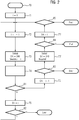
- FIG. 2 a program flow diagram for an automatic addressing of the modular peripheral system 100 is shown.
- the automatic addressing the following are the FIG. 2 and the FIG. 1 considered simultaneously.
- the control module 10 is configured to send the address request 73 as a communication message via a bus system formed by the longitudinal branches 21, 22, wherein the address request 73 has a standard address 240 as the request parameter and the address i to be assigned.
- the sent address request 73 enters the first party 1.
- the first party 1 is in an initial state, since he has not yet been assigned a valid address.
- In this initial state are the first Switching means S1 and the second switching means S2 open, so that the first longitudinal branch 21 and the second longitudinal branch 22 to the following participants 2, ..., 8 is separated.
- the RX receive port of the first party 1 is connected to the receiving unit 40.
- the third switching means S3 is arranged in the first transverse branch 23. Although the third switching means S3 is closed, it is configured in such a way that it selects response messages 74 to the control module 10 and only allows them to pass through to the control module 10.
- FIG. 2 now sends the first participant 1 via its transmitting unit 41, a response message 74, which he has generated for the control module 10.
- the program sequence is to be viewed in the control module 10; for this purpose, the program flowchart has a first branch point 81.
- the branch point 81 evaluates a positive feedback + or a negative feedback - and branches in a positive feedback + to an action 75 for a first switching command and a negative feedback - to an action 76 for a second switching command.
- the control module 10 is designed for this purpose the first switching command, in turn, the respective participants in this case, the first participant 1 is configured to put the first switching means S1 and the second switching means S2 from an open state to a closed state by means of the first switching command, thereby closing the chained Communication path is achieved.
- the action 75 for the first switching command S1 is also checked for a positive + or negative feedback.
- the program sequence is stopped by an error message.
- a reset switching command is issued in the control module 10, which resets all participants 1, ..., 8 in a defined initial state.
- the program flowchart is continued with the incrementing step 72.
- this response message can reach the first transmission element 31 via the TX transmission port of the second subscriber 2 and can be transferred from the first connection element 31 into the RX reception port of the third subscriber 3 via its third switching device S3 his transmitting unit 41 to its TX transmission port again via the first connection means 31 back to the control module 10 reach.
- the control module 10 sends the first switching command to the second party 2, which causes the first switching means S1 and the second switching means S2 of the second party 2 to operate in a closed state and the third switching means S3 to operate in an open state.
- the control module 10 sets the second shift command S2, wherein the second user 2 is configured to, due to the second shift command, the second shunt arm 24 to close the fourth switching means S4, whereby on the one hand, the first end E1 of the subordinate line 102 is marked and on the other a new communication path for further address requests 73 to the other participants 3, ..., 8 is switched.
- the further address request 73 has essentially the same structure as the other address request 73.
- the third party 3 is reached.
- the remaining subscribers 4,..., 8 are supplied with an address via the further second and third connection elements 32, 33, respectively.
- each of the subscribers 1,..., 8 has received a unique address and the result of the address allocation, as well as the switch position of the switching means S1,..., S4 is with the FIG. 3 shown.
Landscapes
- Engineering & Computer Science (AREA)
- Theoretical Computer Science (AREA)
- General Engineering & Computer Science (AREA)
- Physics & Mathematics (AREA)
- General Physics & Mathematics (AREA)
- Computer Hardware Design (AREA)
- Small-Scale Networks (AREA)
Priority Applications (1)
| Application Number | Priority Date | Filing Date | Title |
|---|---|---|---|
| EP20120156861 EP2631810B1 (fr) | 2012-02-24 | 2012-02-24 | Procédé d'attribution d'adresses de participants et système périphérique modulaire de la technique d'automatisation |
Applications Claiming Priority (1)
| Application Number | Priority Date | Filing Date | Title |
|---|---|---|---|
| EP20120156861 EP2631810B1 (fr) | 2012-02-24 | 2012-02-24 | Procédé d'attribution d'adresses de participants et système périphérique modulaire de la technique d'automatisation |
Publications (2)
| Publication Number | Publication Date |
|---|---|
| EP2631810A1 true EP2631810A1 (fr) | 2013-08-28 |
| EP2631810B1 EP2631810B1 (fr) | 2015-01-14 |
Family
ID=45656654
Family Applications (1)
| Application Number | Title | Priority Date | Filing Date |
|---|---|---|---|
| EP20120156861 Active EP2631810B1 (fr) | 2012-02-24 | 2012-02-24 | Procédé d'attribution d'adresses de participants et système périphérique modulaire de la technique d'automatisation |
Country Status (1)
| Country | Link |
|---|---|
| EP (1) | EP2631810B1 (fr) |
Cited By (3)
| Publication number | Priority date | Publication date | Assignee | Title |
|---|---|---|---|---|
| US12150267B2 (en) | 2020-03-27 | 2024-11-19 | Phoenix Contact Gmbh & Co. Kg | Backplane module for electrically connecting a plurality of functional modules, and modular communications system |
| US12156361B2 (en) | 2019-10-09 | 2024-11-26 | Phoenix Contact Gmbh & Co. Kg | Modular interface system for connecting a control device and field devices |
| US12381757B2 (en) | 2019-04-24 | 2025-08-05 | Phoenix Contact Gmbh & Co. Kg | Modular switch for use in a data transmission and control system |
Citations (2)
| Publication number | Priority date | Publication date | Assignee | Title |
|---|---|---|---|---|
| DE10233978A1 (de) * | 2002-07-25 | 2004-02-19 | Infineon Technologies Ag | Bussystem |
| US6745270B1 (en) * | 2001-01-31 | 2004-06-01 | International Business Machines Corporation | Dynamically allocating I2C addresses using self bus switching device |
-
2012
- 2012-02-24 EP EP20120156861 patent/EP2631810B1/fr active Active
Patent Citations (2)
| Publication number | Priority date | Publication date | Assignee | Title |
|---|---|---|---|---|
| US6745270B1 (en) * | 2001-01-31 | 2004-06-01 | International Business Machines Corporation | Dynamically allocating I2C addresses using self bus switching device |
| DE10233978A1 (de) * | 2002-07-25 | 2004-02-19 | Infineon Technologies Ag | Bussystem |
Cited By (3)
| Publication number | Priority date | Publication date | Assignee | Title |
|---|---|---|---|---|
| US12381757B2 (en) | 2019-04-24 | 2025-08-05 | Phoenix Contact Gmbh & Co. Kg | Modular switch for use in a data transmission and control system |
| US12156361B2 (en) | 2019-10-09 | 2024-11-26 | Phoenix Contact Gmbh & Co. Kg | Modular interface system for connecting a control device and field devices |
| US12150267B2 (en) | 2020-03-27 | 2024-11-19 | Phoenix Contact Gmbh & Co. Kg | Backplane module for electrically connecting a plurality of functional modules, and modular communications system |
Also Published As
| Publication number | Publication date |
|---|---|
| EP2631810B1 (fr) | 2015-01-14 |
Similar Documents
| Publication | Publication Date | Title |
|---|---|---|
| EP3131016B1 (fr) | Adressage dynamique | |
| EP3625627B1 (fr) | Flux de sommes pour états réels et signaux de commande d'un système de commande réparti | |
| DE102014108457B3 (de) | Netzwerkverteiler | |
| DE102019114303B3 (de) | Verfahren zum Erfassen von Netzwerkteilnehmer in einem Automatisierungsnetzwerk und Automatisierungsnetzwerk | |
| WO2012000641A2 (fr) | Système de communication permettant de relier des appareils de terrain à un dispositif de commande superposé | |
| EP3871377B1 (fr) | Noeud de distribution, réseau d'automatisation et procédé de transmission de télégrammes | |
| EP3955529A1 (fr) | Unité pour un système de bus, système de bus maître-esclave doté d'une pluralité d'unités et procédé d'adressage des unités d'un système de bus | |
| EP4057596A1 (fr) | Système maître-esclave adressable, ainsi que procédé d'adressage des unités esclaves | |
| DE202014100958U1 (de) | Master-Slave-Steuerungssystem für WS-GS-Netzteile | |
| DE102014105207B4 (de) | Verfahren zum Betreiben eines Kommunikationsnetzwerks und Kommunikationsnetzwerk | |
| EP2631810B1 (fr) | Procédé d'attribution d'adresses de participants et système périphérique modulaire de la technique d'automatisation | |
| EP3008859B1 (fr) | Abonné d'un réseau | |
| AT500044A2 (de) | Bussystem und verfahren zur automatischen adressvergabe | |
| EP3251469B1 (fr) | Procédé pour faire fonctionner des appareils dans un système d'éclairage | |
| DE102012205226A1 (de) | Verfahren zum Betreiben von Geräten in einem Beleuchtungssystem | |
| EP3525476B1 (fr) | Procede de determination de topologie d'un site de communication mobile et un site de communication mobile correspondant | |
| DE102017117288A1 (de) | Datenübertragungsverfahren zwischen einem Drehwinkelgeber und einer Motorsteuereinrichtung oder einer Auswerteeinheit | |
| EP2241062A1 (fr) | Système de communication et procédé de communication avec maîtres de groupe pour la transmission de données série dans le domaine de l'automatisation | |
| DE102005059012A1 (de) | ASI-Sytem zum Anschluß mehrerer Sensoren und/oder Aktuatoren an eine Steuerung | |
| DE112013007045B4 (de) | Schaltung mit hoher Integrationsstufe für ein Fabrikautomatisierungs-Netzwerk und Kommunikationsvorrichtung | |
| DE102011115431B4 (de) | Feldbusnetzwerkadapter und Feldbusnetzwerkteilnehmer mit Feldbusanschlüssen | |
| EP3902208A1 (fr) | Coupleur de bus pour un réseau et procédé de fonctionnement d'un coupleur de bus | |
| DE102006049636B4 (de) | Buskoppler sowie Kommunikationssystem mit Buskoppler | |
| EP4070530B1 (fr) | Procédé de transmission cyclique de données entre des abonnés de communication sur un canal de transmission de données et système de transmission de données | |
| WO2006081885A1 (fr) | Procede et dispositif pour commander le changement d'au moins un appareil pouvant etre mis en reseau, en particulier un appareil menager d'un premier ensemble d'entree de reseau vers un second ensemble |
Legal Events
| Date | Code | Title | Description |
|---|---|---|---|
| PUAI | Public reference made under article 153(3) epc to a published international application that has entered the european phase |
Free format text: ORIGINAL CODE: 0009012 |
|
| AK | Designated contracting states |
Kind code of ref document: A1 Designated state(s): AL AT BE BG CH CY CZ DE DK EE ES FI FR GB GR HR HU IE IS IT LI LT LU LV MC MK MT NL NO PL PT RO RS SE SI SK SM TR |
|
| AX | Request for extension of the european patent |
Extension state: BA ME |
|
| 17P | Request for examination filed |
Effective date: 20140219 |
|
| RBV | Designated contracting states (corrected) |
Designated state(s): AL AT BE BG CH CY CZ DE DK EE ES FI FR GB GR HR HU IE IS IT LI LT LU LV MC MK MT NL NO PL PT RO RS SE SI SK SM TR |
|
| GRAP | Despatch of communication of intention to grant a patent |
Free format text: ORIGINAL CODE: EPIDOSNIGR1 |
|
| INTG | Intention to grant announced |
Effective date: 20140812 |
|
| GRAS | Grant fee paid |
Free format text: ORIGINAL CODE: EPIDOSNIGR3 |
|
| GRAA | (expected) grant |
Free format text: ORIGINAL CODE: 0009210 |
|
| AK | Designated contracting states |
Kind code of ref document: B1 Designated state(s): AL AT BE BG CH CY CZ DE DK EE ES FI FR GB GR HR HU IE IS IT LI LT LU LV MC MK MT NL NO PL PT RO RS SE SI SK SM TR |
|
| REG | Reference to a national code |
Ref country code: GB Ref legal event code: FG4D Free format text: NOT ENGLISH |
|
| REG | Reference to a national code |
Ref country code: CH Ref legal event code: EP |
|
| REG | Reference to a national code |
Ref country code: IE Ref legal event code: FG4D Free format text: LANGUAGE OF EP DOCUMENT: GERMAN |
|
| REG | Reference to a national code |
Ref country code: AT Ref legal event code: REF Ref document number: 707373 Country of ref document: AT Kind code of ref document: T Effective date: 20150215 |
|
| REG | Reference to a national code |
Ref country code: DE Ref legal event code: R096 Ref document number: 502012002079 Country of ref document: DE Effective date: 20150226 |
|
| REG | Reference to a national code |
Ref country code: NL Ref legal event code: VDEP Effective date: 20150114 |
|
| REG | Reference to a national code |
Ref country code: LT Ref legal event code: MG4D |
|
| PG25 | Lapsed in a contracting state [announced via postgrant information from national office to epo] |
Ref country code: BE Free format text: LAPSE BECAUSE OF NON-PAYMENT OF DUE FEES Effective date: 20150228 |
|
| PG25 | Lapsed in a contracting state [announced via postgrant information from national office to epo] |
Ref country code: SE Free format text: LAPSE BECAUSE OF FAILURE TO SUBMIT A TRANSLATION OF THE DESCRIPTION OR TO PAY THE FEE WITHIN THE PRESCRIBED TIME-LIMIT Effective date: 20150114 Ref country code: BG Free format text: LAPSE BECAUSE OF FAILURE TO SUBMIT A TRANSLATION OF THE DESCRIPTION OR TO PAY THE FEE WITHIN THE PRESCRIBED TIME-LIMIT Effective date: 20150414 Ref country code: FI Free format text: LAPSE BECAUSE OF FAILURE TO SUBMIT A TRANSLATION OF THE DESCRIPTION OR TO PAY THE FEE WITHIN THE PRESCRIBED TIME-LIMIT Effective date: 20150114 Ref country code: ES Free format text: LAPSE BECAUSE OF FAILURE TO SUBMIT A TRANSLATION OF THE DESCRIPTION OR TO PAY THE FEE WITHIN THE PRESCRIBED TIME-LIMIT Effective date: 20150114 Ref country code: LT Free format text: LAPSE BECAUSE OF FAILURE TO SUBMIT A TRANSLATION OF THE DESCRIPTION OR TO PAY THE FEE WITHIN THE PRESCRIBED TIME-LIMIT Effective date: 20150114 Ref country code: NO Free format text: LAPSE BECAUSE OF FAILURE TO SUBMIT A TRANSLATION OF THE DESCRIPTION OR TO PAY THE FEE WITHIN THE PRESCRIBED TIME-LIMIT Effective date: 20150414 Ref country code: HR Free format text: LAPSE BECAUSE OF FAILURE TO SUBMIT A TRANSLATION OF THE DESCRIPTION OR TO PAY THE FEE WITHIN THE PRESCRIBED TIME-LIMIT Effective date: 20150114 |
|
| PG25 | Lapsed in a contracting state [announced via postgrant information from national office to epo] |
Ref country code: GR Free format text: LAPSE BECAUSE OF FAILURE TO SUBMIT A TRANSLATION OF THE DESCRIPTION OR TO PAY THE FEE WITHIN THE PRESCRIBED TIME-LIMIT Effective date: 20150415 Ref country code: NL Free format text: LAPSE BECAUSE OF FAILURE TO SUBMIT A TRANSLATION OF THE DESCRIPTION OR TO PAY THE FEE WITHIN THE PRESCRIBED TIME-LIMIT Effective date: 20150114 Ref country code: PL Free format text: LAPSE BECAUSE OF FAILURE TO SUBMIT A TRANSLATION OF THE DESCRIPTION OR TO PAY THE FEE WITHIN THE PRESCRIBED TIME-LIMIT Effective date: 20150114 Ref country code: LV Free format text: LAPSE BECAUSE OF FAILURE TO SUBMIT A TRANSLATION OF THE DESCRIPTION OR TO PAY THE FEE WITHIN THE PRESCRIBED TIME-LIMIT Effective date: 20150114 Ref country code: IS Free format text: LAPSE BECAUSE OF FAILURE TO SUBMIT A TRANSLATION OF THE DESCRIPTION OR TO PAY THE FEE WITHIN THE PRESCRIBED TIME-LIMIT Effective date: 20150514 Ref country code: RS Free format text: LAPSE BECAUSE OF FAILURE TO SUBMIT A TRANSLATION OF THE DESCRIPTION OR TO PAY THE FEE WITHIN THE PRESCRIBED TIME-LIMIT Effective date: 20150114 |
|
| REG | Reference to a national code |
Ref country code: CH Ref legal event code: PL |
|
| REG | Reference to a national code |
Ref country code: DE Ref legal event code: R097 Ref document number: 502012002079 Country of ref document: DE |
|
| PG25 | Lapsed in a contracting state [announced via postgrant information from national office to epo] |
Ref country code: MC Free format text: LAPSE BECAUSE OF FAILURE TO SUBMIT A TRANSLATION OF THE DESCRIPTION OR TO PAY THE FEE WITHIN THE PRESCRIBED TIME-LIMIT Effective date: 20150114 Ref country code: EE Free format text: LAPSE BECAUSE OF FAILURE TO SUBMIT A TRANSLATION OF THE DESCRIPTION OR TO PAY THE FEE WITHIN THE PRESCRIBED TIME-LIMIT Effective date: 20150114 Ref country code: LI Free format text: LAPSE BECAUSE OF NON-PAYMENT OF DUE FEES Effective date: 20150228 Ref country code: CZ Free format text: LAPSE BECAUSE OF FAILURE TO SUBMIT A TRANSLATION OF THE DESCRIPTION OR TO PAY THE FEE WITHIN THE PRESCRIBED TIME-LIMIT Effective date: 20150114 Ref country code: DK Free format text: LAPSE BECAUSE OF FAILURE TO SUBMIT A TRANSLATION OF THE DESCRIPTION OR TO PAY THE FEE WITHIN THE PRESCRIBED TIME-LIMIT Effective date: 20150114 Ref country code: RO Free format text: LAPSE BECAUSE OF FAILURE TO SUBMIT A TRANSLATION OF THE DESCRIPTION OR TO PAY THE FEE WITHIN THE PRESCRIBED TIME-LIMIT Effective date: 20150114 Ref country code: CH Free format text: LAPSE BECAUSE OF NON-PAYMENT OF DUE FEES Effective date: 20150228 Ref country code: SK Free format text: LAPSE BECAUSE OF FAILURE TO SUBMIT A TRANSLATION OF THE DESCRIPTION OR TO PAY THE FEE WITHIN THE PRESCRIBED TIME-LIMIT Effective date: 20150114 |
|
| REG | Reference to a national code |
Ref country code: IE Ref legal event code: MM4A |
|
| PLBE | No opposition filed within time limit |
Free format text: ORIGINAL CODE: 0009261 |
|
| STAA | Information on the status of an ep patent application or granted ep patent |
Free format text: STATUS: NO OPPOSITION FILED WITHIN TIME LIMIT |
|
| 26N | No opposition filed |
Effective date: 20151015 |
|
| PG25 | Lapsed in a contracting state [announced via postgrant information from national office to epo] |
Ref country code: IE Free format text: LAPSE BECAUSE OF NON-PAYMENT OF DUE FEES Effective date: 20150224 |
|
| REG | Reference to a national code |
Ref country code: FR Ref legal event code: PLFP Year of fee payment: 5 |
|
| PG25 | Lapsed in a contracting state [announced via postgrant information from national office to epo] |
Ref country code: SI Free format text: LAPSE BECAUSE OF FAILURE TO SUBMIT A TRANSLATION OF THE DESCRIPTION OR TO PAY THE FEE WITHIN THE PRESCRIBED TIME-LIMIT Effective date: 20150114 |
|
| GBPC | Gb: european patent ceased through non-payment of renewal fee |
Effective date: 20160224 |
|
| PG25 | Lapsed in a contracting state [announced via postgrant information from national office to epo] |
Ref country code: MT Free format text: LAPSE BECAUSE OF FAILURE TO SUBMIT A TRANSLATION OF THE DESCRIPTION OR TO PAY THE FEE WITHIN THE PRESCRIBED TIME-LIMIT Effective date: 20150114 |
|
| PG25 | Lapsed in a contracting state [announced via postgrant information from national office to epo] |
Ref country code: GB Free format text: LAPSE BECAUSE OF NON-PAYMENT OF DUE FEES Effective date: 20160224 |
|
| REG | Reference to a national code |
Ref country code: FR Ref legal event code: PLFP Year of fee payment: 6 |
|
| PG25 | Lapsed in a contracting state [announced via postgrant information from national office to epo] |
Ref country code: SM Free format text: LAPSE BECAUSE OF FAILURE TO SUBMIT A TRANSLATION OF THE DESCRIPTION OR TO PAY THE FEE WITHIN THE PRESCRIBED TIME-LIMIT Effective date: 20150114 Ref country code: HU Free format text: LAPSE BECAUSE OF FAILURE TO SUBMIT A TRANSLATION OF THE DESCRIPTION OR TO PAY THE FEE WITHIN THE PRESCRIBED TIME-LIMIT; INVALID AB INITIO Effective date: 20120224 |
|
| PG25 | Lapsed in a contracting state [announced via postgrant information from national office to epo] |
Ref country code: CY Free format text: LAPSE BECAUSE OF FAILURE TO SUBMIT A TRANSLATION OF THE DESCRIPTION OR TO PAY THE FEE WITHIN THE PRESCRIBED TIME-LIMIT Effective date: 20150114 |
|
| PG25 | Lapsed in a contracting state [announced via postgrant information from national office to epo] |
Ref country code: PT Free format text: LAPSE BECAUSE OF FAILURE TO SUBMIT A TRANSLATION OF THE DESCRIPTION OR TO PAY THE FEE WITHIN THE PRESCRIBED TIME-LIMIT Effective date: 20150514 |
|
| PG25 | Lapsed in a contracting state [announced via postgrant information from national office to epo] |
Ref country code: TR Free format text: LAPSE BECAUSE OF FAILURE TO SUBMIT A TRANSLATION OF THE DESCRIPTION OR TO PAY THE FEE WITHIN THE PRESCRIBED TIME-LIMIT Effective date: 20150114 |
|
| PG25 | Lapsed in a contracting state [announced via postgrant information from national office to epo] |
Ref country code: LU Free format text: LAPSE BECAUSE OF NON-PAYMENT OF DUE FEES Effective date: 20150224 |
|
| REG | Reference to a national code |
Ref country code: FR Ref legal event code: PLFP Year of fee payment: 7 |
|
| REG | Reference to a national code |
Ref country code: AT Ref legal event code: MM01 Ref document number: 707373 Country of ref document: AT Kind code of ref document: T Effective date: 20170224 |
|
| PG25 | Lapsed in a contracting state [announced via postgrant information from national office to epo] |
Ref country code: AT Free format text: LAPSE BECAUSE OF NON-PAYMENT OF DUE FEES Effective date: 20170224 |
|
| PG25 | Lapsed in a contracting state [announced via postgrant information from national office to epo] |
Ref country code: MK Free format text: LAPSE BECAUSE OF FAILURE TO SUBMIT A TRANSLATION OF THE DESCRIPTION OR TO PAY THE FEE WITHIN THE PRESCRIBED TIME-LIMIT Effective date: 20150114 |
|
| PG25 | Lapsed in a contracting state [announced via postgrant information from national office to epo] |
Ref country code: AL Free format text: LAPSE BECAUSE OF FAILURE TO SUBMIT A TRANSLATION OF THE DESCRIPTION OR TO PAY THE FEE WITHIN THE PRESCRIBED TIME-LIMIT Effective date: 20150114 |
|
| PGFP | Annual fee paid to national office [announced via postgrant information from national office to epo] |
Ref country code: DE Payment date: 20250417 Year of fee payment: 14 |
|
| PGFP | Annual fee paid to national office [announced via postgrant information from national office to epo] |
Ref country code: IT Payment date: 20260225 Year of fee payment: 15 |
|
| PGFP | Annual fee paid to national office [announced via postgrant information from national office to epo] |
Ref country code: FR Payment date: 20260213 Year of fee payment: 15 |