EP3902208A1 - Coupleur de bus pour un réseau et procédé de fonctionnement d'un coupleur de bus - Google Patents
Coupleur de bus pour un réseau et procédé de fonctionnement d'un coupleur de bus Download PDFInfo
- Publication number
- EP3902208A1 EP3902208A1 EP21162498.6A EP21162498A EP3902208A1 EP 3902208 A1 EP3902208 A1 EP 3902208A1 EP 21162498 A EP21162498 A EP 21162498A EP 3902208 A1 EP3902208 A1 EP 3902208A1
- Authority
- EP
- European Patent Office
- Prior art keywords
- bus
- data
- coupler
- network
- input data
- Prior art date
- Legal status (The legal status is an assumption and is not a legal conclusion. Google has not performed a legal analysis and makes no representation as to the accuracy of the status listed.)
- Granted
Links
Images


Classifications
-
- H—ELECTRICITY
- H04—ELECTRIC COMMUNICATION TECHNIQUE
- H04L—TRANSMISSION OF DIGITAL INFORMATION, e.g. TELEGRAPHIC COMMUNICATION
- H04L12/00—Data switching networks
- H04L12/28—Data switching networks characterised by path configuration, e.g. LAN [Local Area Networks] or WAN [Wide Area Networks]
- H04L12/40—Bus networks
- H04L12/40006—Architecture of a communication node
- H04L12/40013—Details regarding a bus controller
-
- H—ELECTRICITY
- H04—ELECTRIC COMMUNICATION TECHNIQUE
- H04L—TRANSMISSION OF DIGITAL INFORMATION, e.g. TELEGRAPHIC COMMUNICATION
- H04L12/00—Data switching networks
- H04L12/28—Data switching networks characterised by path configuration, e.g. LAN [Local Area Networks] or WAN [Wide Area Networks]
- H04L12/42—Loop networks
-
- H—ELECTRICITY
- H04—ELECTRIC COMMUNICATION TECHNIQUE
- H04B—TRANSMISSION
- H04B10/00—Transmission systems employing electromagnetic waves other than radio-waves, e.g. infrared, visible or ultraviolet light, or employing corpuscular radiation, e.g. quantum communication
- H04B10/27—Arrangements for networking
- H04B10/278—Bus-type networks
-
- H—ELECTRICITY
- H04—ELECTRIC COMMUNICATION TECHNIQUE
- H04L—TRANSMISSION OF DIGITAL INFORMATION, e.g. TELEGRAPHIC COMMUNICATION
- H04L12/00—Data switching networks
- H04L12/28—Data switching networks characterised by path configuration, e.g. LAN [Local Area Networks] or WAN [Wide Area Networks]
- H04L12/2854—Wide area networks, e.g. public data networks
- H04L12/2856—Access arrangements, e.g. Internet access
- H04L12/2869—Operational details of access network equipments
- H04L12/2878—Access multiplexer, e.g. DSLAM
- H04L12/2879—Access multiplexer, e.g. DSLAM characterised by the network type on the uplink side, i.e. towards the service provider network
- H04L12/2885—Arrangements interfacing with optical systems
-
- H—ELECTRICITY
- H04—ELECTRIC COMMUNICATION TECHNIQUE
- H04L—TRANSMISSION OF DIGITAL INFORMATION, e.g. TELEGRAPHIC COMMUNICATION
- H04L12/00—Data switching networks
- H04L12/28—Data switching networks characterised by path configuration, e.g. LAN [Local Area Networks] or WAN [Wide Area Networks]
- H04L12/40—Bus networks
- H04L12/40052—High-speed IEEE 1394 serial bus
- H04L12/40091—Bus bridging
-
- H—ELECTRICITY
- H04—ELECTRIC COMMUNICATION TECHNIQUE
- H04L—TRANSMISSION OF DIGITAL INFORMATION, e.g. TELEGRAPHIC COMMUNICATION
- H04L12/00—Data switching networks
- H04L12/28—Data switching networks characterised by path configuration, e.g. LAN [Local Area Networks] or WAN [Wide Area Networks]
- H04L12/42—Loop networks
- H04L2012/421—Interconnected ring systems
Definitions
- the invention relates to a bus coupler for a network, in particular for an optical ring network, and a method for operating a bus coupler for a network, in particular an optical ring network.
- Various network types are known from automation and control technology, which are used, for example, to control different devices from a specific unit or to call up data recorded by sensor devices.
- couplers connected to a network have interfaces to other devices.
- the couplers are also connected to one another and can thereby form a closed ring.
- Data packets also known as "telegrams"
- telegrams are transmitted from the connected devices to a coupler and sent from there to another coupler.
- Another device connected to the additional coupler can then receive the telegram.
- a system can be designed in such a way that, even with a ring configuration, the entire ring is practically never used.
- a ring of optical connections is built up, but in practice it is operated like a line structure. The last connection to close the ring is only used if another line fails. Switching takes place via a master device in the ring network. Since data is never sent along a closed ring, no addressing is required with this solution. There are long switchover times, as errors first have to be detected on the master device.
- the bus coupler for a network comprises a bus subscriber interface for data connection with at least one bus subscriber device, a bus receiving interface for receiving bus input data via a bus line and a Bus transmission interface for sending bus output data via the bus line. It also includes a control unit which is set up to generate bus output data based on user input data received via the bus user interface, the bus send data including bus control data, and to a further bus by means of the bus send interface -Coupler to transmit. The control unit is also set up to determine a control signal based on the bus input data received by means of the bus receiving interface and to forward the bus input data to the further bus coupler based on the determined control signal.
- the transmission and forwarding of data within the network can advantageously be controlled particularly efficiently.
- the bus coupler does not simply forward data received from the bus user device, in particular a so-called telegram, to other user devices via the bus line.
- the subscriber input data are supplemented by the bus control data, which control the subsequent forwarding through the bus line.
- the bus output data transmitted from the bus coupler to the next bus coupler are thus generated on the basis of the subscriber input data and also include the bus control data.
- the control data are formed in such a way that the bus coupler can recognize when it receives the telegram again, this time by means of the bus receiving interface because it has passed through the network.
- One advantage of the invention is the direct forwarding of the data in a network, in particular configured as a ring, without evaluating the data, in particular with regard to a sender and / or recipient.
- the decision to send a specific telegram forwarding or removing it from the ring can, in particular, be made after the first byte has been received and evaluated. This also ensures that data is not forwarded in the ring if this is no longer necessary. In this way, the ring is not blocked by superfluous data, especially after the failure of a device that is responsible for terminating the forwarding in known systems.
- a telegram is sent in the network in such a way that the bus control data precedes the data of the telegram, in particular as the subscriber received data.
- the transmitted data are then structured in such a way that the bus control data are sent before the subscriber receive data to be transmitted is sent.
- the bus control data can have a length of one byte and in particular be designed as a "control byte" so that they can be inserted into the typically provided 1.5-byte gap between several telegrams within the network.
- the bus control data are arranged within the bus send data in such a way that they are sent before the data of a telegram to be transmitted and are received by another bus coupler. This ensures that the bus coupler of the network can decide whether or not to forward this data to the next bus coupler on the basis of the bus control data received first, even in the case of a byte for byte transmission.
- the bus control data can have a different length, for example several bytes, for example in order to implement a system with multi-level control of the forwarding.
- the bus line is formed by at least two bus couplers coupled to one another, the bus couplers being connected to one another for data purposes, in particular in series.
- the connections between individual bus couplers are called segments of the bus line.
- the bus couplers are set up to receive signals from connected bus subscriber devices and to send a so-called telegram via the bus line to which the bus coupler is connected and to receive and receive telegrams via the bus line to output the bus subscriber devices, which in turn are connected to the bus coupler. They are also set up to send a telegram received from another bus coupler via the bus line to another bus coupler forward so that the telegram runs through the network from one bus coupler to the next until it is no longer forwarded by a bus coupler and is thus deleted from the network.
- the interruption of the forwarding or the deletion of a telegram from the network takes place in particular under specified conditions; the forwarding of the telegram along the bus line from one bus coupler to the next is thereby particularly interrupted.
- control unit is also set up to transmit the bus input data received by means of the bus receiving interface as a function of the control signal byte by byte to the further bus coupler.
- the forwarding of data, in particular a telegram, in the network by the bus coupler takes place in particular "byte by byte", that is, the bus coupler does not only send the telegram on after it has received a larger data packet or the entire telegram and has analyzed it if necessary. Rather, the individual bytes of the telegram are forwarded as directly as possible to the next bus coupler.
- the output of a first bus coupler is coupled to the input of a second bus coupler; Furthermore, the output of the second bus coupler is coupled to the input of the first bus coupler.
- the network includes further bus couplers, these are connected, for example, between the first and second bus couplers, for example by connecting the output of the first bus coupler to the input of the further bus coupler and the output of the further bus coupler to the Input of the second bus coupler are coupled; Furthermore, a further bus coupler can be connected between the output of the second bus coupler and the input of the first bus coupler. This means that the bus line has a ring structure, in particular as a closed ring.
- a telegram is transmitted in the network in a ring configuration from a first bus coupler to the next and from there on until it reaches the first bus coupler again; without an abort condition, the telegram is thus continuously transmitted along the ring structure of the bus line. Over time, telegrams can thus accumulate in the network, which use the available bandwidth and the capacity of the connected devices.
- a termination condition it can be defined, for example, that a bus coupler no longer forwards a telegram if it has already forwarded it once. To do this, however, the bus coupler must recognize the telegram. However, if a bus coupler is to forward received telegrams byte by byte, the bus coupler cannot recognize a telegram as a whole before it is forwarded.
- the bus coupler of the invention uses the bus control data to control the forwarding.
- the bus line comprises an optical waveguide.
- the bus receiving interface and the bus transmitting interface of the bus coupler are suitable for optical communication.
- optical interfaces of the bus coupler are suitable for the data connection by means of an optical waveguide.
- one transmitting and / or one receiving unit is provided for each interface.
- an optical ring network at least two devices are connected with their optical interfaces in a ring configuration, that is, the optical output of the first device is connected to the input of the second device, furthermore the output of the second device is connected to the input of the first device. If there are more than two devices, the ring formed by the devices is expanded accordingly.
- the bus user interface of the bus coupler provides in particular a data input via which the bus coupler can receive data from at least one connected bus user device, and a data output via which the bus coupler sends data to the at least one connected participant device.
- the bus subscriber interface is set up to receive the subscriber input data from the bus subscriber device by means of a cable-based data transmission. This advantageously creates a particularly simple connection to various participants whose data can be transmitted via the network.
- the bus subscriber interface of the bus coupler can correspond to a so-called "copper side" in the communication of the bus coupler Connection between the bus coupler and the at least one connected bus user device takes place via a wired data line.
- other types of data connections can be used between the subscriber device and the bus coupler, in particular optical data conductors or waveguides or radio-based transmission methods.
- the coupler that originally sent the telegram recognizes the completion of a round through the ring network, i.e. it recognizes a telegram originally sent by it and removes it, if necessary under additional conditions, for example if a Receipt of the telegram is confirmed by a connected target device. If the originally sending device of a telegram fails after sending, the telegram cannot be removed from the ring in this way.
- control data include addressing assigned to the bus coupler.
- the bus coupler can be identified on the basis of addressing within the ring network. This is usually not the case, since segment couplers in the ring network are typically only used for the transmission of data and cannot be addressed or recognized individually. This means in particular that the bus coupler can be addressed and / or recognized on the basis of the addressing assigned to it, while it is not visible in particular to the bus user devices connected to the ring network.
- control unit is also set up to determine the control signal in such a way that received bus input data is forwarded to the further bus coupler if the bus received data does not include any addressing assigned to the bus coupler.
- the forwarding is not reversed executed when the addressing assigned to the bus coupler is included in the bus received data.
- the forwarding is advantageously controlled and, if necessary, limited in a particularly simple manner.
- a telegram is only forwarded by a bus coupler if it detects that the telegram was not sent into the network by itself.
- a telegram is therefore deleted from the network if it has already run through a ring configuration.
- no bus send data for forwarding the bus receive data is generated and transmitted if the bus receive data includes the addressing assigned to the respective bus coupler itself.
- the control unit generates the bus transmission data, in particular based on the subscriber input data, in such a way that the bus coupler can be identified as the original sender.
- the bus couplers are not addressed, as they only forward the telegrams in the network and are not themselves addressees of the forwarded data.
- the telegram routed into the network by the bus coupler is marked in such a way that the bus coupler recognizes the telegram again when it has passed through the network.
- the bus coupler can then interrupt the forwarding of the telegram, especially after it has completely run through the network.
- the address of a connected bus user device can be used to address the bus coupler.
- the bus coupler can, for example, be assigned the address of that bus subscriber device from which it receives the first subscriber input data for forwarding the first telegram into the network.
- This addressing can then also be used for further telegrams that are generated on the basis of user input data from other bus user devices, since the addressing assigned to the bus coupler is only used for communication with the other bus couplers and conflicts are excluded from addressing.
- bus output data are in turn generated for output via the bus transmit interface and transmitted to the next bus coupler.
- the received bus input data can in particular be forwarded directly or new bus output data can be generated, with bus control data in particular can be newly created or modified.
- control data can be added that were not previously included in the bus input data.
- already existing bus control data can be changed, for example in order to change the value of a counter or switch information, for example cancel switch information, or in order to set a delete bit in a predetermined manner.
- control unit is also set up to generate modified bus output data for forwarding the received bus reception data.
- bus control data comprised by the bus receive data are modified.
- the bus control data can include a counter that is changed when the telegram is forwarded by the bus coupler in order to determine how often the telegram has already been forwarded or how often it has passed a specific bus coupler in the network .
- the forwarding can be canceled after the counter has reached a certain level. Continuous circulation of unnecessary data in the ring network can thus be avoided, for example if other mechanisms fail, for example if one of the devices involved fails.
- the bus control data also includes cancellation switch information, which is in particular designed as a cancellation bit, the control unit in particular being set up to determine the control signal as a function of the cancellation switch information.
- Cancellation switch information is designed in such a way that by comparing the cancellation switch information with a specific value, it can be decided directly whether the data should be forwarded or not.
- one of the bus couplers of the network is designed as a master coupler.
- This sets the deletion bit for example, when it forwards a telegram.
- a deletion bit By setting or not setting a deletion bit, it is particularly easy to distinguish between two states in which the data is forwarded should be or not.
- such a deletion bit can be set when the master coupler forwards data so that, when they reach the master coupler again, they are pre-marked so that they are not forwarded again.
- a data connection between bus subscriber devices by means of a "Process Field Bus", Profibus-DB, can be carried out via the network or one or more bus couplers connected to one another in the network.
- the forwarding of data or telegrams in the network between the bus couplers takes place without affecting the protocol used for communication between bus subscriber devices.
- further developments of the invention can provide that the control of the forwarding is integrated in the bus or by means of the bus coupler in the protocol, for example by addressing the bus coupler included in the protocol.
- a bus coupler for a network in particular for an optical ring network
- subscriber input data are received and bus transmission data are generated on the basis of the received subscriber input data, the bus transmission data including bus control data.
- bus input data is received, a control signal is determined on the basis of the received bus input data and the bus input data is forwarded in the network on the basis of the determined control signal.
- the method is designed in particular to operate the bus coupler. It therefore has the same advantages as the bus coupler according to the invention.
- the invention also relates to a network with at least two bus couplers as described above.
- the invention also relates to a method for operating a network, in particular an optical circular network.
- the network here comprises at least two bus couplers according to the description above, which are operated by means of the method described above.
- bus couplers 1, 2, 3, 4, 5 are coupled to one another via a bus line 10 in a ring configuration, that is to say they are coupled in series in such a way that a closed ring is formed.
- the parts of the bus line 10 which connect the individual bus couplers 1, 2, 3, 4, 5 to one another are referred to as "bus segments".
- the bus power 10 is formed by means of optical waveguides, in particular by means of glass fiber lines.
- all bus couplers 1, 2, 3, 4, 5 are basically constructed in the same way, but the construction is only shown in detail for a first bus coupler 1.
- a bus subscriber interface 1a is set up to establish a data connection via which data can be received and sent by means of wired, "copper-side" communication with connected bus subscriber devices 11, 12.
- a bus receiving interface 1b and a bus transmitting interface 1c of the bus coupler 1 are set up to receive data from connected further bus couplers 2, 5 or to transmit data to them. In the exemplary embodiment, this communication between the bus couplers 1, 2, 3, 4, 5 takes place via the optical bus line 10.
- the bus coupler 1 also includes a control unit 1d, which in particular controls the operation of the bus coupler 1 controls. The control takes place by means of control signals that are generated by the control unit 1d, in particular for controlling the bus user interface 1a and the bus receiving interface 1b and the bus transmitting interface 1c.
- the bus couplers 1, 2, 3, 4, 5 are coupled to one another in series via the bus line 10 so that the bus transmit interface 1c of the first bus coupler with a corresponding bus receive interface (not shown) of the second bus -Coupler 2 is coupled, so that data can be sent from the first 1 to the second bus coupler 2 via this segment of the bus line 10. The data can then be transmitted from the second bus coupler 2 to the third bus coupler 3 and so on until they are transmitted again from the last bus coupler 5 of the network shown to the first bus coupler 1 and from there via the bus Receiving interface 1b.
- a bus user device 11 sends user input data to the bus coupler 1 via the bus user interface 1a designed as a "copper side" .
- This takes place via a cable connection, in particular a metal cable.
- the data transmission can take place in a different manner.
- the subscriber input data include, for example, data of a measured value that is recorded by the bus subscriber device 11, or data for requesting further data from another bus subscriber device 12, 21, 31, 41, 51 or for controlling one other bus user device 12, 21, 31, 41, 51.
- the control unit 1d of the bus coupler 1 generates bus output data which, in the exemplary embodiment, include the subscriber input data which are to be transmitted as a so-called "telegram" over the bus or over the bus line 10, in particular to one of the further bus Subscriber devices 21, 31, 41, 51.
- the bus output data include bus control data for controlling the transmission in the network and through the bus couplers 1, 2, 3, 4, 5, with the exemplary embodiment the bus control data includes a "control byte" which will be described below with reference to Figure 2 is explained in more detail.
- This control byte is placed directly in front of the telegram to be transmitted.
- a gap of 1.5 bytes is usually provided between the telegrams that are transmitted in the ring network, and in the exemplary embodiment the control byte is inserted into this gap, or this gap is correspondingly reduced by the control byte.
- the data is forwarded byte by byte, that is, the bus coupler 1 forwards each received byte directly.
- the forwarding can take place in a different way, for example in packets of a larger data volume.
- control byte 60 is as in FIG Figure 2 shown: It comprises 8 bits, of which 7 bits are used to accommodate an addressing assigned to the bus coupler 1, which is shown in the Figure 2 is represented by the designation of the bits "ADR_0" to "ADR_6".
- a “TRB” is also provided, which functions as cancel switch information.
- TRB stands for "telegram remove bit” and this bit is set depending on whether the telegram following control byte 60 is to be forwarded in the network or not. In particular, after evaluating the TRB, the bus coupler 1 directly decides whether the telegram is to be forwarded.
- the addressing assigned to the bus coupler 1 is determined in the method on the basis of data that the bus coupler 1 receives from the connected bus user devices 11, 12.
- the data received from the bus user devices 11, 12 each include information about an addressing of these bus user devices 11, 12, which is assigned to them in the network as a unique identification.
- the bus coupler 1 takes on the addressing of that bus subscriber device 11, 12 from which it receives the first data for itself.
- the addressing of the bus coupler 1 is only used for the purpose of forwarding data via the bus line 10, in particular as a "ring address" of the bus coupler 1, so that it is used for the bus user devices 11, 12 connected in the network , 21, 31, 41, 51 remains "invisible” so that in particular the addressing in the network of the bus user devices 11, 12, 21, 31, 41, 51 can be clearly assigned to one another.
- care must be taken to ensure that it can be stored in the 7 bits of the control byte 60 in the exemplary embodiment; if necessary, the addressing is done differently in further examples determines that it can be stored in control byte 60.
- the addressing remains on the bus coupler 1, in particular permanently and / or until a voltage reset.
- control unit 1d controls the bus coupler 1 in such a way that data received from the previous bus coupler 5 can be forwarded.
- Bus input data are received by means of the bus receiving interface 1b.
- the bus control data included is recorded and it is determined whether the requirements for forwarding the data are met.
- the control byte is analyzed and checked for this purpose. If the conditions for forwarding are met or no deletion conditions are met, bus output data are generated, in the simplest case the received bus input data are forwarded unchanged and sent from the bus transmission interface 1c to the next bus coupler 2. If necessary, the bus control data or the control byte are modified.
- the deletion condition provided is that a telegram is not forwarded if the addressing comprised by the received control byte matches the addressing assigned to the bus coupler 1 itself. It is thus recognized whether the bus coupler 1 has forwarded the telegram itself into the network and in this case the telegram is no longer forwarded.
- the bus coupler 1 receives user input data from one of the connected bus user devices 11, 12.
- the user input data include a so-called "telegram" with data that is sent via the bus line 10 to one of the others Bus subscriber devices 11, 12, 21, 31, 41, 51 connected to the network are to be transmitted.
- this transmission takes place by means of a Profibus DB protocol.
- the control unit 1d checks whether the bus coupler 1 already has a ring address, that is, whether the bus coupler 1 is assigned an address. If this is not the case, an addressing is determined in a step S13 on the basis of the received subscriber input data: the subscriber input data include information about a network address of the bus user device 11, 12 from which the user input data originate. This means in particular that the bus coupler 1 is assigned an addressing which corresponds to the network address of the first bus user device 11, 12 from which it receives user input data.
- bus control data are generated which, in the exemplary embodiment, consist of a control byte.
- the addressing assigned to the bus coupler 1 is stored in the control byte.
- the bus control data are placed in front of the telegram. This means that the bus output data include the control byte and the telegram to be transmitted.
- step S15 the bus output data generated in this way are transmitted to the next bus coupler 2 via the bus transmission interface 1c.
- the bus coupler 1 receives bus input data via the bus receiving interface 1b.
- the bus input data are formed in particular in accordance with the bus output data sent above in step S15, that is to say they include bus control data, in particular a control byte, and a telegram.
- step S22 it is checked whether the control data include an addressing that corresponds to the own ring address of the bus coupler 1.
- step S23 no forwarding is carried out in a step S23. This means that if it is determined that a telegram has completed an entire cycle through the ring network, the telegram is deleted from the network or is no longer forwarded.
- the telegram is forwarded in a step S24.
- the forwarding takes place "byte for byte" and unchanged by sending via the bus transmission interface 1c to the next bus coupler 2.
- the telegram is also transmitted to the connected bus user devices 11, 12.
- the bus control data are removed in a step S25 and the telegram is sent to the bus user devices 11, 12 via the bus user interface 1a in a step S26.
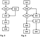
- the third embodiment shown corresponds essentially to the first embodiment of FIG Figure 3 .
- the bus coupler 1 takes on an additional function here as a so-called “ring master”, that is to say as a device for the higher-level control of the forwarding of telegrams in the network.
- ring master a bus coupler 1 which is used to carry out the method as shown in FIG Figure 3 configured as a "ring slave”.
- a step S31 user input data are received via the bus user interface 1a.
- a step S32 it is checked whether an addressing has already been assigned to the bus coupler 1 and, if necessary, the assignment takes place as described above in a step S33.
- bus output data are generated as described above, a control byte being placed in front of the telegram to be transmitted.
- the TRB ( telegram remove bit ) is now set in the control byte in a step S35.
- this setting of the TRB corresponds to the information that the telegram should no longer be forwarded the next time the TRB is evaluated, i.e. that the telegram should be removed from the ring network.
- step S36 the bus output data are transmitted via the bus transmission interface 1c via the bus line 10 to the next bus coupler 2.
- the fourth embodiment shown corresponds essentially to the second embodiment of FIG Figure 4 .
- the bus coupler 1 also takes on the function of the "ring master” here and carries out a higher-level control of the forwarding of telegrams in the network.
- bus input data are received via the bus receiving interface 1b.
- a step S42 it is checked whether the information about an addressing comprised by the bus input data corresponds to the own ring address of the bus coupler 1. If this is the case, the telegram is not forwarded in a step S44.
- a step S43 it is checked whether the TRB is set, that is, whether the ring master has already sent or forwarded the telegram beforehand. If the TRB is set, the telegram is also not forwarded in step S44.
- the TRB is now set in a step S45 before the forwarding takes place by means of bus output data via the bus transmission interface 1c in a step S46.
- the bus control data are removed in a step S47 and the telegram is output to the connected bus user devices 11, 12 via the bus user interface 1a in a step S48.
- the TRB can be viewed as a counter that distinguishes between 0 and 1. After reaching a full cycle, the telegram is deleted from the ring network.
Landscapes
- Engineering & Computer Science (AREA)
- Computer Networks & Wireless Communication (AREA)
- Signal Processing (AREA)
- Computing Systems (AREA)
- Physics & Mathematics (AREA)
- Electromagnetism (AREA)
- Small-Scale Networks (AREA)
Applications Claiming Priority (1)
| Application Number | Priority Date | Filing Date | Title |
|---|---|---|---|
| DE102020110753.6A DE102020110753A1 (de) | 2020-04-21 | 2020-04-21 | Bus-Koppler für ein Netzwerk und Verfahren zum Betreiben eines Bus-Kopplers |
Publications (2)
| Publication Number | Publication Date |
|---|---|
| EP3902208A1 true EP3902208A1 (fr) | 2021-10-27 |
| EP3902208B1 EP3902208B1 (fr) | 2023-08-09 |
Family
ID=74874666
Family Applications (1)
| Application Number | Title | Priority Date | Filing Date |
|---|---|---|---|
| EP21162498.6A Active EP3902208B1 (fr) | 2020-04-21 | 2021-03-15 | Coupleur de bus pour un réseau et procédé de fonctionnement d'un coupleur de bus |
Country Status (4)
| Country | Link |
|---|---|
| US (1) | US11582061B2 (fr) |
| EP (1) | EP3902208B1 (fr) |
| CN (1) | CN113542088B (fr) |
| DE (1) | DE102020110753A1 (fr) |
Families Citing this family (1)
| Publication number | Priority date | Publication date | Assignee | Title |
|---|---|---|---|---|
| LU502098B1 (de) * | 2022-05-17 | 2023-12-04 | Phoenix Contact Gmbh & Co | Primäres Kommunikationsgerät, Ankopplungsmodul und Kommunikationssystem |
Citations (3)
| Publication number | Priority date | Publication date | Assignee | Title |
|---|---|---|---|---|
| EP1890434A1 (fr) * | 2005-05-31 | 2008-02-20 | NEC Corporation | Systeme de reseau en boucle a commutation de paquets, procede de transfert de paquets et noeuds |
| US20100034204A1 (en) * | 2006-11-02 | 2010-02-11 | Masahiro Sakauchi | Packet ring network system, packet transfer method and interlink node |
| CN105790843A (zh) | 2014-12-25 | 2016-07-20 | 沈阳高精数控智能技术股份有限公司 | 一种适用于Profibus的光纤通信方法 |
Family Cites Families (10)
| Publication number | Priority date | Publication date | Assignee | Title |
|---|---|---|---|---|
| DE4426094C2 (de) * | 1994-07-22 | 1998-04-16 | Siemens Nixdorf Inf Syst | Datenreduktion für Buskoppler |
| CN1853439A (zh) * | 2003-05-22 | 2006-10-25 | 研究三角协会 | 具有准时信令的光突发交换网络系统和方法 |
| FR2893469B1 (fr) * | 2005-11-17 | 2007-12-14 | Alcatel Sa | Dispositifs perfectionnes de transmission de donnees pour des equipements de communication d'un reseau optique passif |
| DE102008018633B4 (de) * | 2008-04-11 | 2013-10-10 | Phoenix Contact Gmbh & Co. Kg | Verfahren, Buskomponenten und Steuerungssystem zur Ethernet-basierten Steuerung eines Automatisierungssystems |
| DE102010003448A1 (de) * | 2010-03-30 | 2011-10-06 | Beckhoff Automation Gmbh | Adressierungsverfahren und Kommunikationsnetzwerk mit einem solchen Adressierungsverfahren |
| EP2866387B1 (fr) * | 2013-10-25 | 2016-11-30 | Amrona AG | Système de bus et procédé de fonctionnement d'un tel système de bus |
| CN103944639B (zh) * | 2014-03-31 | 2017-01-25 | 天津大学 | 一种具有自愈功能的无源光纤星环网 |
| DE102015105929A1 (de) * | 2015-04-17 | 2016-10-20 | Phoenix Contact Gmbh & Co. Kg | Automatisierungsgerät zum redundanten Steuern eines Busteilnehmers |
| EP3154220A1 (fr) * | 2015-10-09 | 2017-04-12 | Siemens Schweiz AG | Unite de couplage de bus et systeme de bus dote d'une unite de couplage de bus |
| DE102017002805B4 (de) * | 2017-03-23 | 2018-10-04 | WAGO Verwaltungsgesellschaft mit beschränkter Haftung | Verfahren zum Betrieb eines Bussystems eines Automatisierungssystems |
-
2020
- 2020-04-21 DE DE102020110753.6A patent/DE102020110753A1/de active Pending
-
2021
- 2021-03-09 CN CN202110255085.8A patent/CN113542088B/zh active Active
- 2021-03-15 EP EP21162498.6A patent/EP3902208B1/fr active Active
- 2021-04-20 US US17/234,819 patent/US11582061B2/en active Active
Patent Citations (3)
| Publication number | Priority date | Publication date | Assignee | Title |
|---|---|---|---|---|
| EP1890434A1 (fr) * | 2005-05-31 | 2008-02-20 | NEC Corporation | Systeme de reseau en boucle a commutation de paquets, procede de transfert de paquets et noeuds |
| US20100034204A1 (en) * | 2006-11-02 | 2010-02-11 | Masahiro Sakauchi | Packet ring network system, packet transfer method and interlink node |
| CN105790843A (zh) | 2014-12-25 | 2016-07-20 | 沈阳高精数控智能技术股份有限公司 | 一种适用于Profibus的光纤通信方法 |
Also Published As
| Publication number | Publication date |
|---|---|
| US20210328827A1 (en) | 2021-10-21 |
| EP3902208B1 (fr) | 2023-08-09 |
| US11582061B2 (en) | 2023-02-14 |
| DE102020110753A1 (de) | 2021-10-21 |
| CN113542088B (zh) | 2024-03-29 |
| CN113542088A (zh) | 2021-10-22 |
Similar Documents
| Publication | Publication Date | Title |
|---|---|---|
| EP2961106B1 (fr) | Réseau, abonné de tête et procédé de transmission de données | |
| EP0610999B1 (fr) | Installation radiologique | |
| DE102014112082A1 (de) | Verteilerknoten, Automatisierungsnetz und Verfahren zum Übertragen von echtzeitrelevanten und nicht-echtzeitrelevanten Datenpaketen | |
| EP2866387A1 (fr) | Système de bus et procédé de fonctionnement d'un tel système de bus | |
| EP0381011A2 (fr) | Réseau de transmission avec des noeuds commutables | |
| EP3854028B1 (fr) | Procédé de détection d'abonnés du réseau dans un réseau d'automatisation et réseau d'automatisation | |
| EP2915289B1 (fr) | Répéteur, système de communication can et procédé de transmission d'un télégramme de données au sein d'un réseau de communication can | |
| DE102018102067A1 (de) | Drahtloses IO-Link-Kommunikationsnetzwerk mit einem zusätzlichen Master und Verfahren zu dessen Betrieb | |
| DE60218888T2 (de) | Schnittstelleneinrichtung für ein faseroptisches kommunikationsnetz und verfahren zur verwendung einer solchen einrichtung | |
| EP3902208B1 (fr) | Coupleur de bus pour un réseau et procédé de fonctionnement d'un coupleur de bus | |
| DE3826895C2 (fr) | ||
| DE2828707A1 (de) | Ringfoermiges datenuebertragungssystem | |
| DE3139960A1 (de) | Datengeraet-diagnosesystem | |
| DE10142372B4 (de) | Vorrichtung und Verfahren zum Wiederherstellen von Verbindungen in automatisch schaltbaren optischen Netzen | |
| DE10139155C2 (de) | Signalisierungs-Proxy-Einrichtung zum automatischen Aufbau von Ersatzpfaden in optischen Netzen | |
| DE102014210505A1 (de) | Übertragungseinheit mit Prüffunktion | |
| EP0509114A1 (fr) | Méthode pour la transmission de données à plusieurs stations | |
| DE102021122686A1 (de) | Verfahren zum betreiben eines netzwerks | |
| DE29908608U1 (de) | Netzwerk sowie Koppelgerät zur Verbindung zweier Segmente in einem derartigen Netzwerk und Netzwerkteilnehmer | |
| DE10037969C2 (de) | Verfahren zur Erkennung einer flexiblen Vernetzung von Baugruppen bei beliebiger Netztopologie sowie zum Informationsaustausch zwischen solchen Baugruppen | |
| EP3632049B1 (fr) | Émission de signal d'état | |
| DE102005059012A1 (de) | ASI-Sytem zum Anschluß mehrerer Sensoren und/oder Aktuatoren an eine Steuerung | |
| DE102011088812A1 (de) | Verfahren zum Übertragen von Nutzdaten | |
| EP0173265B1 (fr) | Procédé pour la transmission de signaux de données entre postes d'abonnés d'un central de commutation de données | |
| DE19704021A1 (de) | Lichtwellenleiter-Bussystem mit in einer Ringstruktur angeordneten Teilnehmern |
Legal Events
| Date | Code | Title | Description |
|---|---|---|---|
| PUAI | Public reference made under article 153(3) epc to a published international application that has entered the european phase |
Free format text: ORIGINAL CODE: 0009012 |
|
| STAA | Information on the status of an ep patent application or granted ep patent |
Free format text: STATUS: THE APPLICATION HAS BEEN PUBLISHED |
|
| AK | Designated contracting states |
Kind code of ref document: A1 Designated state(s): AL AT BE BG CH CY CZ DE DK EE ES FI FR GB GR HR HU IE IS IT LI LT LU LV MC MK MT NL NO PL PT RO RS SE SI SK SM TR |
|
| B565 | Issuance of search results under rule 164(2) epc |
Effective date: 20210914 |
|
| STAA | Information on the status of an ep patent application or granted ep patent |
Free format text: STATUS: REQUEST FOR EXAMINATION WAS MADE |
|
| 17P | Request for examination filed |
Effective date: 20220412 |
|
| RBV | Designated contracting states (corrected) |
Designated state(s): AL AT BE BG CH CY CZ DE DK EE ES FI FR GB GR HR HU IE IS IT LI LT LU LV MC MK MT NL NO PL PT RO RS SE SI SK SM TR |
|
| GRAP | Despatch of communication of intention to grant a patent |
Free format text: ORIGINAL CODE: EPIDOSNIGR1 |
|
| STAA | Information on the status of an ep patent application or granted ep patent |
Free format text: STATUS: GRANT OF PATENT IS INTENDED |
|
| RIC1 | Information provided on ipc code assigned before grant |
Ipc: H04L 12/42 20060101AFI20230329BHEP |
|
| INTG | Intention to grant announced |
Effective date: 20230417 |
|
| GRAS | Grant fee paid |
Free format text: ORIGINAL CODE: EPIDOSNIGR3 |
|
| GRAA | (expected) grant |
Free format text: ORIGINAL CODE: 0009210 |
|
| STAA | Information on the status of an ep patent application or granted ep patent |
Free format text: STATUS: THE PATENT HAS BEEN GRANTED |
|
| P01 | Opt-out of the competence of the unified patent court (upc) registered |
Effective date: 20230627 |
|
| AK | Designated contracting states |
Kind code of ref document: B1 Designated state(s): AL AT BE BG CH CY CZ DE DK EE ES FI FR GB GR HR HU IE IS IT LI LT LU LV MC MK MT NL NO PL PT RO RS SE SI SK SM TR |
|
| REG | Reference to a national code |
Ref country code: GB Ref legal event code: FG4D Free format text: NOT ENGLISH |
|
| REG | Reference to a national code |
Ref country code: CH Ref legal event code: EP |
|
| REG | Reference to a national code |
Ref country code: DE Ref legal event code: R096 Ref document number: 502021001174 Country of ref document: DE |
|
| REG | Reference to a national code |
Ref country code: IE Ref legal event code: FG4D Free format text: LANGUAGE OF EP DOCUMENT: GERMAN |
|
| REG | Reference to a national code |
Ref country code: LT Ref legal event code: MG9D |
|
| REG | Reference to a national code |
Ref country code: NL Ref legal event code: MP Effective date: 20230809 |
|
| PG25 | Lapsed in a contracting state [announced via postgrant information from national office to epo] |
Ref country code: GR Free format text: LAPSE BECAUSE OF FAILURE TO SUBMIT A TRANSLATION OF THE DESCRIPTION OR TO PAY THE FEE WITHIN THE PRESCRIBED TIME-LIMIT Effective date: 20231110 |
|
| PG25 | Lapsed in a contracting state [announced via postgrant information from national office to epo] |
Ref country code: IS Free format text: LAPSE BECAUSE OF FAILURE TO SUBMIT A TRANSLATION OF THE DESCRIPTION OR TO PAY THE FEE WITHIN THE PRESCRIBED TIME-LIMIT Effective date: 20231209 |
|
| PG25 | Lapsed in a contracting state [announced via postgrant information from national office to epo] |
Ref country code: SE Free format text: LAPSE BECAUSE OF FAILURE TO SUBMIT A TRANSLATION OF THE DESCRIPTION OR TO PAY THE FEE WITHIN THE PRESCRIBED TIME-LIMIT Effective date: 20230809 Ref country code: RS Free format text: LAPSE BECAUSE OF FAILURE TO SUBMIT A TRANSLATION OF THE DESCRIPTION OR TO PAY THE FEE WITHIN THE PRESCRIBED TIME-LIMIT Effective date: 20230809 Ref country code: PT Free format text: LAPSE BECAUSE OF FAILURE TO SUBMIT A TRANSLATION OF THE DESCRIPTION OR TO PAY THE FEE WITHIN THE PRESCRIBED TIME-LIMIT Effective date: 20231211 Ref country code: NO Free format text: LAPSE BECAUSE OF FAILURE TO SUBMIT A TRANSLATION OF THE DESCRIPTION OR TO PAY THE FEE WITHIN THE PRESCRIBED TIME-LIMIT Effective date: 20231109 Ref country code: NL Free format text: LAPSE BECAUSE OF FAILURE TO SUBMIT A TRANSLATION OF THE DESCRIPTION OR TO PAY THE FEE WITHIN THE PRESCRIBED TIME-LIMIT Effective date: 20230809 Ref country code: LV Free format text: LAPSE BECAUSE OF FAILURE TO SUBMIT A TRANSLATION OF THE DESCRIPTION OR TO PAY THE FEE WITHIN THE PRESCRIBED TIME-LIMIT Effective date: 20230809 Ref country code: LT Free format text: LAPSE BECAUSE OF FAILURE TO SUBMIT A TRANSLATION OF THE DESCRIPTION OR TO PAY THE FEE WITHIN THE PRESCRIBED TIME-LIMIT Effective date: 20230809 Ref country code: IS Free format text: LAPSE BECAUSE OF FAILURE TO SUBMIT A TRANSLATION OF THE DESCRIPTION OR TO PAY THE FEE WITHIN THE PRESCRIBED TIME-LIMIT Effective date: 20231209 Ref country code: HR Free format text: LAPSE BECAUSE OF FAILURE TO SUBMIT A TRANSLATION OF THE DESCRIPTION OR TO PAY THE FEE WITHIN THE PRESCRIBED TIME-LIMIT Effective date: 20230809 Ref country code: GR Free format text: LAPSE BECAUSE OF FAILURE TO SUBMIT A TRANSLATION OF THE DESCRIPTION OR TO PAY THE FEE WITHIN THE PRESCRIBED TIME-LIMIT Effective date: 20231110 Ref country code: FI Free format text: LAPSE BECAUSE OF FAILURE TO SUBMIT A TRANSLATION OF THE DESCRIPTION OR TO PAY THE FEE WITHIN THE PRESCRIBED TIME-LIMIT Effective date: 20230809 |
|
| PG25 | Lapsed in a contracting state [announced via postgrant information from national office to epo] |
Ref country code: PL Free format text: LAPSE BECAUSE OF FAILURE TO SUBMIT A TRANSLATION OF THE DESCRIPTION OR TO PAY THE FEE WITHIN THE PRESCRIBED TIME-LIMIT Effective date: 20230809 |
|
| PG25 | Lapsed in a contracting state [announced via postgrant information from national office to epo] |
Ref country code: ES Free format text: LAPSE BECAUSE OF FAILURE TO SUBMIT A TRANSLATION OF THE DESCRIPTION OR TO PAY THE FEE WITHIN THE PRESCRIBED TIME-LIMIT Effective date: 20230809 |
|
| PG25 | Lapsed in a contracting state [announced via postgrant information from national office to epo] |
Ref country code: SM Free format text: LAPSE BECAUSE OF FAILURE TO SUBMIT A TRANSLATION OF THE DESCRIPTION OR TO PAY THE FEE WITHIN THE PRESCRIBED TIME-LIMIT Effective date: 20230809 Ref country code: RO Free format text: LAPSE BECAUSE OF FAILURE TO SUBMIT A TRANSLATION OF THE DESCRIPTION OR TO PAY THE FEE WITHIN THE PRESCRIBED TIME-LIMIT Effective date: 20230809 Ref country code: ES Free format text: LAPSE BECAUSE OF FAILURE TO SUBMIT A TRANSLATION OF THE DESCRIPTION OR TO PAY THE FEE WITHIN THE PRESCRIBED TIME-LIMIT Effective date: 20230809 Ref country code: EE Free format text: LAPSE BECAUSE OF FAILURE TO SUBMIT A TRANSLATION OF THE DESCRIPTION OR TO PAY THE FEE WITHIN THE PRESCRIBED TIME-LIMIT Effective date: 20230809 Ref country code: DK Free format text: LAPSE BECAUSE OF FAILURE TO SUBMIT A TRANSLATION OF THE DESCRIPTION OR TO PAY THE FEE WITHIN THE PRESCRIBED TIME-LIMIT Effective date: 20230809 Ref country code: CZ Free format text: LAPSE BECAUSE OF FAILURE TO SUBMIT A TRANSLATION OF THE DESCRIPTION OR TO PAY THE FEE WITHIN THE PRESCRIBED TIME-LIMIT Effective date: 20230809 Ref country code: SK Free format text: LAPSE BECAUSE OF FAILURE TO SUBMIT A TRANSLATION OF THE DESCRIPTION OR TO PAY THE FEE WITHIN THE PRESCRIBED TIME-LIMIT Effective date: 20230809 |
|
| REG | Reference to a national code |
Ref country code: DE Ref legal event code: R097 Ref document number: 502021001174 Country of ref document: DE |
|
| PG25 | Lapsed in a contracting state [announced via postgrant information from national office to epo] |
Ref country code: IT Free format text: LAPSE BECAUSE OF FAILURE TO SUBMIT A TRANSLATION OF THE DESCRIPTION OR TO PAY THE FEE WITHIN THE PRESCRIBED TIME-LIMIT Effective date: 20230809 |
|
| PLBE | No opposition filed within time limit |
Free format text: ORIGINAL CODE: 0009261 |
|
| STAA | Information on the status of an ep patent application or granted ep patent |
Free format text: STATUS: NO OPPOSITION FILED WITHIN TIME LIMIT |
|
| 26N | No opposition filed |
Effective date: 20240513 |
|
| PG25 | Lapsed in a contracting state [announced via postgrant information from national office to epo] |
Ref country code: SI Free format text: LAPSE BECAUSE OF FAILURE TO SUBMIT A TRANSLATION OF THE DESCRIPTION OR TO PAY THE FEE WITHIN THE PRESCRIBED TIME-LIMIT Effective date: 20230809 |
|
| REG | Reference to a national code |
Ref country code: CH Ref legal event code: PL |
|
| PG25 | Lapsed in a contracting state [announced via postgrant information from national office to epo] |
Ref country code: BG Free format text: LAPSE BECAUSE OF FAILURE TO SUBMIT A TRANSLATION OF THE DESCRIPTION OR TO PAY THE FEE WITHIN THE PRESCRIBED TIME-LIMIT Effective date: 20230809 |
|
| PG25 | Lapsed in a contracting state [announced via postgrant information from national office to epo] |
Ref country code: LU Free format text: LAPSE BECAUSE OF NON-PAYMENT OF DUE FEES Effective date: 20240315 |
|
| PG25 | Lapsed in a contracting state [announced via postgrant information from national office to epo] |
Ref country code: MC Free format text: LAPSE BECAUSE OF FAILURE TO SUBMIT A TRANSLATION OF THE DESCRIPTION OR TO PAY THE FEE WITHIN THE PRESCRIBED TIME-LIMIT Effective date: 20230809 |
|
| PG25 | Lapsed in a contracting state [announced via postgrant information from national office to epo] |
Ref country code: MC Free format text: LAPSE BECAUSE OF FAILURE TO SUBMIT A TRANSLATION OF THE DESCRIPTION OR TO PAY THE FEE WITHIN THE PRESCRIBED TIME-LIMIT Effective date: 20230809 Ref country code: LU Free format text: LAPSE BECAUSE OF NON-PAYMENT OF DUE FEES Effective date: 20240315 Ref country code: BG Free format text: LAPSE BECAUSE OF FAILURE TO SUBMIT A TRANSLATION OF THE DESCRIPTION OR TO PAY THE FEE WITHIN THE PRESCRIBED TIME-LIMIT Effective date: 20230809 |
|
| REG | Reference to a national code |
Ref country code: BE Ref legal event code: MM Effective date: 20240331 |
|
| PG25 | Lapsed in a contracting state [announced via postgrant information from national office to epo] |
Ref country code: BE Free format text: LAPSE BECAUSE OF NON-PAYMENT OF DUE FEES Effective date: 20240331 |
|
| PG25 | Lapsed in a contracting state [announced via postgrant information from national office to epo] |
Ref country code: FR Free format text: LAPSE BECAUSE OF NON-PAYMENT OF DUE FEES Effective date: 20240331 |
|
| PG25 | Lapsed in a contracting state [announced via postgrant information from national office to epo] |
Ref country code: IE Free format text: LAPSE BECAUSE OF NON-PAYMENT OF DUE FEES Effective date: 20240315 |
|
| PG25 | Lapsed in a contracting state [announced via postgrant information from national office to epo] |
Ref country code: IE Free format text: LAPSE BECAUSE OF NON-PAYMENT OF DUE FEES Effective date: 20240315 Ref country code: FR Free format text: LAPSE BECAUSE OF NON-PAYMENT OF DUE FEES Effective date: 20240331 Ref country code: BE Free format text: LAPSE BECAUSE OF NON-PAYMENT OF DUE FEES Effective date: 20240331 Ref country code: CH Free format text: LAPSE BECAUSE OF NON-PAYMENT OF DUE FEES Effective date: 20240331 |
|
| PGFP | Annual fee paid to national office [announced via postgrant information from national office to epo] |
Ref country code: AT Payment date: 20250417 Year of fee payment: 5 |
|
| PG25 | Lapsed in a contracting state [announced via postgrant information from national office to epo] |
Ref country code: CY Free format text: LAPSE BECAUSE OF FAILURE TO SUBMIT A TRANSLATION OF THE DESCRIPTION OR TO PAY THE FEE WITHIN THE PRESCRIBED TIME-LIMIT; INVALID AB INITIO Effective date: 20210315 |
|
| PG25 | Lapsed in a contracting state [announced via postgrant information from national office to epo] |
Ref country code: HU Free format text: LAPSE BECAUSE OF FAILURE TO SUBMIT A TRANSLATION OF THE DESCRIPTION OR TO PAY THE FEE WITHIN THE PRESCRIBED TIME-LIMIT; INVALID AB INITIO Effective date: 20210315 |
|
| PG25 | Lapsed in a contracting state [announced via postgrant information from national office to epo] |
Ref country code: TR Free format text: LAPSE BECAUSE OF FAILURE TO SUBMIT A TRANSLATION OF THE DESCRIPTION OR TO PAY THE FEE WITHIN THE PRESCRIBED TIME-LIMIT Effective date: 20230809 |
|
| PGFP | Annual fee paid to national office [announced via postgrant information from national office to epo] |
Ref country code: GB Payment date: 20260324 Year of fee payment: 6 |
|
| PGFP | Annual fee paid to national office [announced via postgrant information from national office to epo] |
Ref country code: DE Payment date: 20260320 Year of fee payment: 6 |