EP2632323B1 - Système de remplacement sensoriel et extrasensoriel périphérique - Google Patents
Système de remplacement sensoriel et extrasensoriel périphérique Download PDFInfo
- Publication number
- EP2632323B1 EP2632323B1 EP11835396.0A EP11835396A EP2632323B1 EP 2632323 B1 EP2632323 B1 EP 2632323B1 EP 11835396 A EP11835396 A EP 11835396A EP 2632323 B1 EP2632323 B1 EP 2632323B1
- Authority
- EP
- European Patent Office
- Prior art keywords
- display
- sensors
- pressure
- foot
- likelihood
- Prior art date
- Legal status (The legal status is an assumption and is not a legal conclusion. Google has not performed a legal analysis and makes no representation as to the accuracy of the status listed.)
- Active
Links
Images




Classifications
-
- A—HUMAN NECESSITIES
- A61—MEDICAL OR VETERINARY SCIENCE; HYGIENE
- A61B—DIAGNOSIS; SURGERY; IDENTIFICATION
- A61B5/00—Measuring for diagnostic purposes; Identification of persons
- A61B5/103—Measuring devices for testing the shape, pattern, colour, size or movement of the body or parts thereof, for diagnostic purposes
- A61B5/1036—Measuring load distribution, e.g. podologic studies
-
- A—HUMAN NECESSITIES
- A61—MEDICAL OR VETERINARY SCIENCE; HYGIENE
- A61B—DIAGNOSIS; SURGERY; IDENTIFICATION
- A61B5/00—Measuring for diagnostic purposes; Identification of persons
- A61B5/103—Measuring devices for testing the shape, pattern, colour, size or movement of the body or parts thereof, for diagnostic purposes
- A61B5/1036—Measuring load distribution, e.g. podologic studies
- A61B5/1038—Measuring plantar pressure during gait
-
- A—HUMAN NECESSITIES
- A61—MEDICAL OR VETERINARY SCIENCE; HYGIENE
- A61B—DIAGNOSIS; SURGERY; IDENTIFICATION
- A61B5/00—Measuring for diagnostic purposes; Identification of persons
- A61B5/40—Detecting, measuring or recording for evaluating the nervous system
- A61B5/4029—Detecting, measuring or recording for evaluating the nervous system for evaluating the peripheral nervous systems
- A61B5/4041—Evaluating nerves condition
- A61B5/4047—Evaluating nerves condition afferent nerves, i.e. nerves that relay impulses to the central nervous system
-
- A—HUMAN NECESSITIES
- A61—MEDICAL OR VETERINARY SCIENCE; HYGIENE
- A61B—DIAGNOSIS; SURGERY; IDENTIFICATION
- A61B5/00—Measuring for diagnostic purposes; Identification of persons
- A61B5/68—Arrangements of detecting, measuring or recording means, e.g. sensors, in relation to patient
- A61B5/6801—Arrangements of detecting, measuring or recording means, e.g. sensors, in relation to patient specially adapted to be attached to or worn on the body surface
- A61B5/6802—Sensor mounted on worn items
- A61B5/6804—Garments; Clothes
- A61B5/6807—Footwear
-
- A—HUMAN NECESSITIES
- A61—MEDICAL OR VETERINARY SCIENCE; HYGIENE
- A61B—DIAGNOSIS; SURGERY; IDENTIFICATION
- A61B5/00—Measuring for diagnostic purposes; Identification of persons
- A61B5/72—Signal processing specially adapted for physiological signals or for diagnostic purposes
-
- A—HUMAN NECESSITIES
- A61—MEDICAL OR VETERINARY SCIENCE; HYGIENE
- A61B—DIAGNOSIS; SURGERY; IDENTIFICATION
- A61B5/00—Measuring for diagnostic purposes; Identification of persons
- A61B5/74—Details of notification to user or communication with user or patient; User input means
- A61B5/7455—Details of notification to user or communication with user or patient; User input means characterised by tactile indication, e.g. vibration or electrical stimulation
-
- A—HUMAN NECESSITIES
- A61—MEDICAL OR VETERINARY SCIENCE; HYGIENE
- A61B—DIAGNOSIS; SURGERY; IDENTIFICATION
- A61B2562/00—Details of sensors; Constructional details of sensor housings or probes; Accessories for sensors
- A61B2562/04—Arrangements of multiple sensors of the same type
- A61B2562/046—Arrangements of multiple sensors of the same type in a matrix array
Definitions
- a peripheral sensory and "supersensory” quantification, replacement, augmentation and analysis system is provided. More particularly, a data acquisition and transmission unit, a processing unit, and a receiving unit are provided. Some exemplary applications of the system include uses in healthcare, athletics, occupational health and safety and the military. Prominent healthcare uses include the management of peripheral neuropathy, lower extremity amputees and other rehabilitating patients.
- peripheral neuropathy or any other condition leading to inadequate sensation
- Sixty percent of peripheral neuropathy is secondary to Diabetes, with the remaining 40% being attributed to all other causes.
- peripheral neuropathy The consequences of peripheral neuropathy are manifold. First, this loss of protective sensation leads inadequate plantar feedback and therefore unchecked pressure distribution, leading to focal ischemia, pressure necrosis, ulceration, and then finally, infection and gangrene. Second, impaired sensation leads to balance dysfunction ("mal-equilibrioception”) and subsequent gait and mobility issues. Normal equilibrioception results from a coordination of visual, vestibular, and tactile/proprioceptive (predominantly plantar) inputs. While some variation exists between individuals, humans typically require two intact systems to achieve normal balance perception.
- US 2010/268122 A1 by D Marie et al. discloses a pressure monitoring method and system for warning a patient or caregiver that soft tissue pressure has exceeded some predetermined level to minimize or prevent soft tissue damage.
- the system utilizes a dome-shaped sensor pad assembly and monitors the electrical outputs of the sensors over a preselected time period.
- the system generates audible and visual warnings if the cumulative output signal exceeds a predetermined cumulative threshold until the soft tissue pressure drops below the predetermined pressure level.
- the audible and visual warnings are to indicate that the patient should move or be moved.
- the system has extensive applications in athletics and activity monitoring and optimization, including individual and group tracking, team dynamic analysis, quantification of kinetics and kinematics, performance quantification, compliance assessment and activity mapping.
- Military applications include the development of sensory replacement and augmentation systems for the purposes of detection of, and alerting the user to, pertinent environmental features and imminent danger (including, but not limited to sensing methods involving detection of: TNT, landmines, foreign bodies, heat (infrared), radiation (Geiger), sulphur dioxide, and other chemicals of interest).
- Occupational Health and Safety applications include the exemplary case of a lower extremity-based device that is used to detect (and alert the user or employee to) situations of over-lifting or improper lifting.
- This force and kinetics/kinematics application also has uses in healthcare monitoring (in rehabilitating, users of prosthetics, and diabetic, cardiac, obese, post-cancer and post-operative patients, for example).
- the current gold standard of care includes primary prevention via diabetes education and prescription of traditional orthotic insoles. Beyond this, reactionary wound care and ulcer/infection control is the standard of care. This is an outdated approach applying principles of sickcare, not preventative healthcare that the present system offers. Further, in terms of economics, the present system carries huge potential savings for both the patient and the healthcare system, detailed as follows.
- Figure 1 shows an exemplary system employing two parts: an input device, such as the input device 3, which will receive and transmit pressure readings from across a foot; and a receiving device, such as the wristband 1 or a back display 2.
- an input device such as the input device 3
- a receiving device such as the wristband 1 or a back display 2.
- an input device designed to record pressures along the bottom of the foot is provided.
- the input device is an insole.
- the pressure data is sent to one of a series of potential receiving devices, such as a specially designed wristwatch, described in greater detail below.
- the communication system may be based on a wireless communication, and is therefore able to interact with a whole host of devices for ease of information transfer and/or personal health monitoring.
- Potential receiving devices include (but are not limited to) wristwatches, USB keys, enabled dongles, cellular telephones and personal laptops.
- Another potential receiving device is a stimulator designed to be worn on the back, described in greater detail below, which will thus send a stimulus, in the form of a display (in the form of an electrotactile, electrotextile, vibrotactile, chemotactile, temperature- and/or pressure-mediated stimulus) to the user.
- a stimulus in the form of a display (in the form of an electrotactile, electrotextile, vibrotactile, chemotactile, temperature- and/or pressure-mediated stimulus) to the user.
- the sensate skin of the back will receive the stimulus, and through the phenomenon of neural plasticity, the user- with enough practice- may learn to interpret the stimulus as input from the foot. Together with the input device, this receiving device creates a sensory replacement or augmentation system.
- the receiving device is made to contain software for data requisition.
- the data requisition software is engineered to transmit data in the form of a real-time, differential electrical impulse over the embedded stimulators in the back display.
- the system described herein can be advantageously employed for the prevention and treatment of pressure-related diabetic foot disease (e.g. balance and gait issues, ulceration, infection, and amputation).
- Other uses include applications in patient rehabilitation (amputation- and stroke-related, for example), athletic and/or activity monitoring, military and OH&S uses.
- the sensors can be embedded in a custom- or generic-made insole, for example.
- the data acquired by the system can be used for custom-made, pressure-relieving foot orthotics, as well as for relay of pressure status to the patient/user or a third party (including healthcare practitioners).
- the system can be used to improve gait and balance in patients with decreased/absent plantar sensation (e.g. patients with peripheral neuropathy and/or lower extremity amputation), or to assist an athlete in optimizing foot and ankle manipulation, or, in general, their kinetics and kinematics.
- aspects of the system include the inclusion of further diagnostic sensors and algorithms, enabling the device to measure aspects such as: GPS, heart rate, respiratory rate, blood pressure, temperature, blood oxygen saturation, blood flow, blood or environmental content quantification (e.g. glucose, electrolytes, minerals, oxygen, carbon dioxide, carbon monoxide, HbAIC, Ethanol, protein, lipid, carbohydrate, Cortisol, lactate, pH, pro- and antiinflammatory markers, MMPs, Growth Factors, bacterial content), hydration status/tissue turgor, joint position, features of gait analysis (including supination and pronation), device breakdown, pedometry, accelerometry, velocity, calorimetry, centre of gravity or centre of foot position, friction, traction, contact area, connectivity/insulation, EEG data, and/or ECG data.
- environmental content quantification e.g. glucose, electrolytes, minerals, oxygen, carbon dioxide, carbon monoxide, HbAIC, Ethanol, protein, lipid, carbohydrate, Cort
- the input device comprises multiple devices, located at different anatomic (or extra-corporeal) locations on one or many individuals or objects.
- the output system comprises multiple devices, located at different anatomic (or extra-corporeal) locations on one or many individuals or objects.
- the input and output devices can be the same or different devices.
- the pressure sensor technology of this system can be applied to help prevent and manage pressure ulcers on various parts of the body, including (but not limited to) the foot, leg, buttock, sacrum, back, elbow, shoulder/scapula and scalp.
- the technology may also be used to enable tactile feedback in robotic surgery and applications related to surgical (and other forms of tactile- or sensor-based) education.
- the present system can be used to prevent and treat Diabetic Foot Disease, and improve gait and balance issues in patients with decreased or absent plantar sensory feedback.
- the present system has a low-profile, ergonomic, user-friendly device utilizing ultra-low power consumption, provides improved quality of life for the users of the device, has potential for cost-effectiveness and global healthcare system savings, and may employ state-of-the-art wireless technology and innovative materials.
- the low profile and ergonomic features of the stimulator are derived from the use of light and thin sensors/stimulators. Low power can be achieved through the choice of wireless communication protocol, type of sensor and stimulator as well as the chipset and electronics used.
- Preferred input devices include any foot-based system (e.g. insoles, shoes/boots, casts, lower limb prostheses, pads that can be adhered to the bottom of an amputation stump, etc.), and any hand-based system (e.g. gloves, mitts). Beyond these peripherally attached devices, other inputs of interest would be developed with the intention of preventing other common areas for pressure ulcer development (e.g. clothing or mats to detect when the patient is at risk of developing buttock, sacral, ischial, scapular, and scalp ulceration). Further, the present system can be realized in. but is not limited to, lone sensors (that are adhesive and/or bandage based, for example), anklets, air-casts, splints, prosthetics and dressings themselves.
- lone sensors that are adhesive and/or bandage based, for example
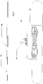
- Figure 3 illustrates one exemplary embodiment of the input device
- An insole containing an array 11 of embedded pressure or force sensors for monitoring of pressure or force distribution (real-time or sporadic) over the bottom of the foot is provided.
- the array of pressure sensors can be distributed over, and laminated within, an upper surface 12 of a low compression, polyurethane insole that is made of a resiliently flexible material that is designed to fit in a shoe.
- the pressure sensors are, for example, low power piezoelectric or piezoresistive capacitive sensors.
- the pressure sensors are A401 FlexiForce sensors produced by Tekscan, Inc. of South Boston, MA.
- a wireless transmission node 13 Contained within the insole bulk, or an affixed device, is a wireless transmission node 13 designed for integration and transmission of, for example, a 4 Hz wireless signal containing "real-time" or sporadic information pertaining to pressure or force distribution (or any other measured other input) from the foot or other anatomic location, including-but not limited to- the sole.
- the array 11 of pressure sensors communicate with the wireless transmission node 13 via a ribbon cable 14.
- the input device, as well as the other devices described herein can employ a low power chipset that is run by a real-time operating system (RTOS), which enables communication through low power wired or wireless protocols, such as, but not limited to ANT+, ZigBee, Gazel, Bluetooth and Bluetooth LE protocols.
- RTOS real-time operating system
- a cushion layer 15 is provided under the array 11 of pressure sensors.
- a support layer 16 is provided under the cushion layer 15.
- the support layer extends from the heel to the toes. Alternatively, the support layer extends merely from the heel to the arch.
- a low- profile model is a flat, 2D, low-profile insole based of polyurethane, for example.
- Formed models (which may be generic or custom made) may be polyurethane-based, and are three- dimensional molded insoles designed to realign the lower limb with added arch support, with emphasis in design on improving foot function, and relieving associated heel, ankle and limb pain by reducing excess pressure on, as well as pronation and supination of, the foot, or other specific needs of the patient/user.
- This insole is may be based on pressure data acquired from a patient-specific gait analysis.
- the insole is fashioned to support the shape of the foot, whereas in other embodiments, the insole is fashioned as a flat, non- supportive structure.
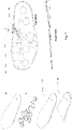
- Figure 4 shows an example in which the sensors 41 are placed in the insole strategically.
- the present inventors recognize that different areas of the foot have different risk categories. For example, the higher risk areas of the foot are based on bony prominences and foot biomechanics. The highest area of risk is the first metatarsal-phalangeal (MTP) joint 46. Other key areas are the other MTP joints, the toes (such as great toe 42), the heel 43 and the lateral side of the foot.
- MTP metatarsal-phalangeal
- pressure sensors are of more use when located at areas in the insole corresponding to pressure points (bony prominences) in the foot, where safe pressure thresholds are more likely to be exceeded.
- the sensors are placed at locations corresponding to bony prominences (pressure points) in the feet, which will not change for generic types of input devices, such as insoles.
- Figure 4 shows some of the sensor locations relative to an arch 44 of the foot and the small toe 45.
- the sensors may be placed in different locations.
- the insole contains embedded (or affixed on a wired or wireless basis) software to receive the pressure or force data from the sensors.
- the embedded (or affixed on a wired or wireless basis) software differentially maps the pressure in an insole, for example, for use in a pressure or force sensing, monitoring, analysis, feedback and/or therapeutic system. This information may be analyzed by a processing unit, described below, in either the input or receiving device.
- a layout of spaced-apart pressure sensors is embedded in the insole, each of which has a predetermined height and diameter.
- the input device provides a real-time pressure or force (or other input) map of the body part being measured: in this example, the sole of the foot.
- recordings from each sensor can be differentially received as a function of time.
- the system will record the broad range of pressures or forces (or other sensor-based inputs) encountered anatomically or physiologically or by an outside body (animate or inanimate).
- the density and location of the sensors will vary somewhat. In examples focusing on simpler output units (e.g. the wristband), sensors will only be placed at high-risk locations, such as bony prominences. In an embodiment including a back display, there is a high density of sensors (likely in the range of one sensor per square centimeter) so that the sensory substitution felt through the back is of a higher resolution, and essentially a "map" of the sole, not just discrete points of concern.
- Figure 4 illustrates an option with eight strategically placed sensors per insole
- Figure 5 illustrates a high-resolution option containing one sensor per regular area, e.g., per square centimeter, over the entire surface of the insole.
- the eight pressure sensors in Figure 4 are located such that each correspond to an area most prone to ulceration (two sensors over the toes, three across the five MTP joints, two along the lateral plantar foot and one on the heel of the foot).
- the example in Figure 5 contains pressure sensors at each regular interval over the surface of the insole and conveys information from the entire plantar surface.
- the example in Figure 5 is more effective with respect to ulcer prevention and plantar sensory replacement or augmentation.
- the use of thin, low-profile pressure (or other) sensors also allow the input device to be realized as a sock, or other article of clothing.
- the insole is removable from a shoe.
- the insole is part of a shoe, or that the said insole is part of a sock.
- the pressure sensors can extend over a variable area within the shoe or the sock.
- the sensor location can change to non-plantar surfaces.
- the location and density of pressure sensors depend on the output device being used. If the output device is based on a wristband output, there would be fewer sensors at key locations.
- Modifications can include additional sensors (to detect, for example, TNT). If a sensor has been included to detect an environmental danger (e.g. in the case of TNT detection), then the sensor would be placed in a location external to the article of clothing itself.
- sensors While a whole host of sensors may be included, additional sensors of particular preference are: temperature, moisture, blood flow and blood glucose sensors. Pressure aside, these are the major potential impediments to the healing of diabetic wounds.
- sensors incorporated to measure physiological phenomenon e.g. blood glucose level
- those sensors would need to be located in proximity to the skin interface.
- Some sensors like temperature sensors, are unique in that they may be located within the article of clothing itself or external to it, depending on whether the external environment or the user's body temperature/immediate skin interface temperature are of interest.
- Environmental temperature sensors would be more useful when incorporated into the part of the insole corresponding to the forefoot. The reason for this is that in diabetics (a group who commonly burns their feet unknowingly), the area of the foot most likely to come in contact with hot environments/flame is the front of the foot; temperature sensors placed at the forefoot would more efficiently diagnose an unsafe environment.
- Environmental temperature sensors embedded with the aim of identifying "danger” zones would be located at or near the skin itself. The temperature of this area would be the primary point of concern, whether or not the user's own body heat impacted that measurement.
- sensors intended to measure blood flow and content-related sensors these may most appropriately be located in anatomic areas with superficial blood vessels (e.g. the dorsum of the foot or around the medial aspect of the ankle).
- Sensors can also be located in non-plantar aspects of the shoe.
- the input device may be contained in a direct contact sensor (applied by an adhesive or band, for example), any article of clothing (gloves, shirts, undergarments, hats, belts, watches, necklaces), or a blanket or pad that may be placed on any anatomic location of interest.
- Therapeutic technologies may be incorporated in the input device, including a transcutaneous electrical nerve stimulation (TENS) unit (for example, for developed ulcers on the foot), and capabilities for temperature, moisture and/or pressure/force auto-adjustment.
- TENS transcutaneous electrical nerve stimulation
- these can also be on an overlay pattern with sensors.
- the system of the present disclosure has extensive applications, depending on the input device and receiving device that the input device is "talking" to via a communication system.
- the communication system is a low-profile, low energy wireless protocol.
- the communication system could comprise any wired and/or wireless, fibre optic, or human circuit.
- the information can be variously transmitted to an output device, such as a wristwatch, a cellular phone, a USB key, a dongle, a personal laptop computer, or a sensory replacement or augmentation system, which will be described in greater detail below.
- Pressure or force (or other sensor-based) data from the input device can be transmitted via a low-profile, ultra-low energy wireless protocol to an output device, such as a wristband.
- An input device such as the foot pod, will simply broadcast data. If a receiver is within range it will acquire the signal and do a "handshake" to sync its respective RF antenna.
- the processing device may be included in the previously described input device, the later described output device, or any other device in the system.
- the processing device in one exemplary aspect of the present disclosure employs a system that does provide the user with continuous, real-time feedback of differential pressures over the entire plantar surface.
- the inventors have found this to be particularly beneficial, as gait is a dynamic exercise employing constant feedback from the plantar sole, and the potential for neural plasticity would theoretically be maximized with a biofeedback loop that projects an output that more closely resembles the native, deficient sense.
- the real-time, differential pressure system can provide the user with information about texture and foreign object location. A rock under a discrete aspect on the foot, for example, may not be appreciated with the aforementioned experimental system.
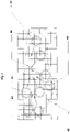
- Figure 6 shows an exemplary algorithm for a pressure sensor data conversion to display scale.
- the algorithm begins at step S 100, at which the array of sensors receives a timer interrupt activation.
- the array of sensors are then turned on at step S105.
- the sensors perform a measurement.
- the performed measurement measures a force or pressure.
- a humidity or temperature is measured.
- the sensors are turned off.
- the likelihood of tissue damage is stratified into four levels.
- Level 1 corresponds to less than 25% of pressure measurements exceeding Pt, within a 15 minute time frame.
- the processing device determines whether 25% of the measurements within the 15 minute time frame exceed Pt. If so, the algorithm proceeds to step S125, where a signal indicating display level 1 is transmitted. If not, the processing device determines at step S130 whether 26-40% of the pressure measurements exceed Pt, within a 15 minute time frame. If so, the algorithm proceeds to step S135, where a signal indicating display level 2 is transmitted. If not, the processing device determines at step S140 whether 41 -50% of the pressure measurements exceed Pt, within a 15 minute time frame.
- step S145 a signal indicating display level 3 is transmitted. If not, the processing device determines at step S150 whether more than 50% of the pressure measurements exceed Pt, within a 15 minute time frame. If so, the algorithm proceeds to step S155, where a signal indicating display level 4 is transmitted. If not, the algorithm proceeds to step S160.
- These signal transmissions can be sent to an output device by a wireless communication, for example. In embodiments in which the processing device is internal to an output device, the signal can be sent within the output device to, for example, a visual display unit. In any case, after the signal transmissions, the algorithm proceeds to step S160.
- step S160 the sensors return to sleep mode. The algorithm then ends.
- a sensor measures the pressure at 4Hz, then within 15 minutes a total of 3600 measurements are taken.
- the processing device generates a signal so that the output device generates an alert for region LI on the display. Measurements exceeding the threshold do not have to be consecutive in order to cause an alert.
- the sensor with the highest value will dictate what the processing device determines. Thus, if any sensor in a region is high, then the processing device will generate a signal for the output device, in which the whole region lights up.
- one embodiment includes a plurality of moisture, temperature, and bacterial load sensors that provide information to the processing device. The processing device then makes a determination based on the information received from those sensors.
- the processing device provides an additional alert to the output device if the temperature difference between two of the temperature sensors exceeds 4 degrees Fahrenheit.
- the software algorithm would be slightly modified as more measurements would be compared to the pressure threshold within the previous 15 minute time frame.
- the 15 minute time frame shifts with the passage of time, which allows for continuous monitoring.
- the processing of the analog (raw) sensor output will change if the sensors are located within the shoe.
- the processing will depend on 1) the biomechanics of the device that the sensor is embedded in; and 2) the subsequent effects those biomechanics have on the raw pressure output.
- the processing device may determine that a foreign object, such as a rock, is in a shoe as follows. If the foreign object is creating a localized pressure increase, the processing device will generate a signal for the display, if the sensor exceeds the threshold for more than a number of readings taken at a standardized frequency. The signal will alert the user to inspect the shoe.
- a foreign object such as a rock
- processing device will be able to also count steps/impact, and from that, cadence can be determined.
- the processing device can also control the sensors to turn off when no readings are received within a predetermined time.
- the device will go into sleep mode between measurements at a predetermined time interval.
- the watch will not go into sleep mode unless it is instructed (e.g., button on watch) or both insoles are out of range. If for example, the left insole is malfunctioning or out of range, the processing device can generate a signal for the display to alert the user of this fact.
- Neuropathy-related applications are concerned with identifying situations in which a pressure threshold as a function of time (e.g. several minutes) has been exceeded.
- the pressure threshold in this situation is relatively low; an alert-able scenario would be one in which even small pressure measurements have been seen (and not offloaded) over the course of a relatively longer period of time.
- the data from the sensors will be processed by the processing device differently, depending on the application. For example, in the case of OH&S applications intended to identify "overlifting," the analysis of the data is done in a way to identify situations in which a relatively higher pressure threshold has been exceeded over a short time period (a single or few-point frame of time).
- a pressure-sensing insole may incorporate the capability to "auto-adjust.”
- the wearer had exceeded (or was at risk for exceeding) a safe pressure threshold over the right first metatarsal head.
- the insole would have incorporated within it the intrinsic capability to re-form in such a way that pressure would be redistributed, and the area of concern would be offloaded.
- An example of accomplishing this would be by way of an insole with discrete air pockets that would auto- inflate or deflate to accomplish the immediate needs of the user by way of a processing device output.
- Modified systems also incorporating this principle of auto-adjustment have ample utility in pressure sore prevention of other forms (e.g. circumvention of sacral ulcer development in bed- and wheelchair-ridden patients).
- the system of the present disclosure encompasses a series of solutions for sensory replacement, augmentation and analysis.
- potential output devices for use with the input device include clothing, wristbands, laptop computers, USB sticks, dongles, cellular or smartphones, televisions, web-based applications, other displays (including, but not limited to, LCD displays), back displays and heads-up display devices, such as those manufactured by 4iiii TM .
- displays including, but not limited to, LCD displays
- back displays and heads-up display devices, such as those manufactured by 4iiii TM .
- these may be located on the body of interest and/or a different body.
- the three most preferable exemplary output devices are: 1) an LCD display; 2) a back display; and 3) a USB key (or other method of directly uploading data to a central location).
- the LCD display is most useful in the situation of a diabetic patient (or other patient with peripheral neuropathy), who wishes to be simply alerted to situations in which damage may be done. This encompasses any patient with a fear of, and therefore a wish to mitigate the risk of, developing pressure-related damage.
- the back display feedback device will be preferable for rehabilitation applications, as the patient will be able to have real-time direct feedback, and substitute sensation for that which he or she is deficient in.
- the same goes for any patient with: a) dense peripheral neuropathy; and/or b) a desire to "feel" the bottom of a prosthesis (e.g. the foot component).
- USB key (or other method of directly uploading data to a central location) output device is most applicable for the collection and analysis of the data by either a third party (e.g. physician) or future analysis by the patient him- or herself (e.g. viewing graphs of pressure encountered over time).
- a third party e.g. physician
- future analysis e.g. viewing graphs of pressure encountered over time.
- a wristband 70 includes the LCD display 72, which is designed to display both graphical and numerical data pertaining to pressure or force incurred on the bottom of the foot.
- the LCD display also includes a node 76 for receiving wireless data signals.
- the wristband can be, for example, a digital timepiece provided with a quartz oscillator, frequency divider and counting circuits, a decoder and a digital electro-optical display device. In addition to the functions described above, the timepiece can be suitable to operate as a standard digital wristwatch to display time data.
- the wristband can also display data received wirelessly from another device, including: GPS, heart rate, respiratory rate, blood pressure, temperature, blood oxygen saturation, blood flow, blood or environmental content quantification (e.g.
- the data received from the input device may be stored and/or uploaded.
- the wristband may also display other sensor data, such as temperature, moisture, and GPS status. Together, these measurements would give a more comprehensive view of the status of the foot.
- the GPS function in particular, would enable tracking with respect to both patient activity compliance and/or athletic monitoring.
- each sole is divided into 7 areas (L1 -L7 and R1-R7). These represent areas that act as different functional units in biomechanics and kinematics of the feet.
- the 7 areas track the placement of the sensors in the input device.
- area L I corresponds to the sensor underneath the second and third toes in Figure 4 .
- Area L2 corresponds to the sensor underneath the great toe 41.
- Area L4 corresponds to the first MTP joint, and area L3 corresponds to the two other sensors along the other MTP joints, as shown in Figure 4 .
- Area L5 corresponds to the two sensors along the lateral foot between the MTP joints and the heel.
- Area L6 corresponds to an arch of the foot, whose sensors are not shown in Figure 4 .
- Area L7 corresponds to the sensor at the heel of Figure 4 .
- the output device includes areas corresponding to the location of each sensor.
- the device preferably displays at area 74 both graphical, auditory, vibrational and/or numerical data regarding the real-time pressures or other sensory data (such as temperature) encountered over the bottom of the foot.
- the wristband can be configured to display these outputs at the same time, or alone in different modes, for example.
- a graphical display portion can include a reproduction of the outline of the feet (or other body part) with color (or grayscale) differentiation based on data from the input device.
- areas lighting up as green (or non-lit) refer to areas with low pressures that would be tolerated by the foot (or other body part) for any duration of time (e.g. ⁇ 30 mmHg or Level 1 ).
- Areas lighting up as yellow (or grayscale) correspond to areas on the sole (or other body part) with pressures exceeding those tolerated (e.g. >30 mmHg), but that have been incurred for less than a specified time threshold (e.g. a 15 minute threshold or Level 2).
- Areas lighting up as red correspond to areas on the sole (or other body part) with pressures exceeding those tolerated (e.g. >30 mmHg), but that have been incurred for greater than the time threshold (or Levels 3 and/or 4).
- the wearer can be alerted via, for example, a visual, vibrational or auditory cue.
- the alert can subside once the pressure in question has been alleviated.
- the color (or shading) will change from red (or dark or blinking) to green (or unlit) if a threshold for pressure offloading time has been reached.
- other schematic systems may be used, such as by using area 74.
- a display 80 mounted on the low back (or other anatomic location) of the patient is provided.
- the display receives information for providing feedback to a user by way of a wired communication.
- the display receives wireless data signals via node 84.
- the display receives data wirelessly, the data is provided to a display grid 86 by way of a ribbon cable 88.
- This stimulating pad can transmit data to a user by an electrotactile, electrotextile, chemotactile, vibrotactile, pressure- or temperature-based output.
- the display can be affixed and held immobile to the area by way of a belt 82 worn around the mid-abdomen, or any other know means of adhering pads to the body that will be readily apparent to one of ordinary skill in the art.
- This device is more acceptable to patients than the previously described Tongue-Display Unit (TDU), as a patient will not have to wear an oral appliance, and will therefore not sacrifice taste, eating, or speech in order to achieve the goal of plantar sensation.
- TDU Tongue-Display Unit
- the lumbar back is an ideal site for plantar sensory replacement and augmentation (but is not the exclusive potential site for an output display), as it has nearly identical two- point discrimination properties (static tactile, electrotactile and vibrotactile) in comparison to the plantar foot, and it comprises a location that would typically not be involved in peripheral neuropathy.
- the device can be easily worn under clothing and is therefore discrete and socially acceptable.
- the device has a low-profile, ergonomic design, utilizing low power consumption.
- the stimulators may be worn in isolation (worn via an adhesive and/or bandage based, for example), socks, casts, anklets, air-casts, splints, prosthetics and dressings themselves, any article of clothing (gloves, shirts, undergarments, hats, belts, watches, necklaces), or a blanket or pad that may be placed on any anatomic location of interest.
- Advantages provided by incorporating the input device in other locations, such as hats or blankets include identification of areas in danger of pressure sore development in at-risk patients.
- plantar sensors convey information to the lumbar back via the stimulator illustrated in Figure 8 .
- the sensor locations are determined by areas in the foot prone to over-pressure, and therefore, complications of peripheral neuropathy, for any reason.
- the sensors in the display are the same as those shown in Figure 3 .
- the sensors are in the back display in analogous locations to the areas L1-L7 and R1-R7 described with reference to Figure 7 .
- the vibrations or stimulus applied to the back are presented in a particular pattern, and will have a fluctuating frequency.
- Each pressure sensor in the insole will correspond to a stimulator over the back.
- the array applied to the back will be fashioned to represent the input (e.g. an insole-shaped area on the back would correspond to an insole-shaped area that is being measured).
- Frequency of the stimulus exerted by any particular stimulator will change according to the pressure measured by the corresponding sensor in the input device. For example, a higher pressure would correspond to a higher frequency stimulus.
- the pressure input magnitude changes over time (e.g. over the course of the gait cycle), so too does the intensity of the corresponding stimulus felt on the back.
- the back display will also alert the user if a safety threshold has been exceeded.
- a safety threshold In the case of an electrotactile system, the voltage that stimulates the back will vary in accordance with the pressure encountered by the foot. If the pressure safety threshold has been exceeded, for example, the user can be alerted by way of a) an increase in the voltage; b) a beep; or c) a vibration at the location corresponding to where the thresholds has been exceeded.
- the vibrating function would function as the best alerting/localizing feature. This alert would only subside when pressure is offloaded, and force encountered is within a normal, safe range.
- a stimulator can amplify the body's feedback.
- the stimulator could either be overlapped with the sensor or immediately adjacent to it. In such a case, the stimulators would be located within the insole itself (or sock, etc.) as with the sensors.
- the input device is a sock or a shoe, which gives greater coverage than the sole of the foot, the position of the stimulators can change.
- Preferred modes of stimulation are electrotactile and vibrotactile. These are preferable for ergonomics in terms of creating a lower profile display. These would also be more comfortable to the user.
- the back display can be realized in male and female styles, and in a spectrum of sizes dictated by waist circumference. For example, sizes can cover a waist circumference range between 23-50 inches.
- An exemplary back display is fitted to the patient for maximum comfort.
- the output device employed herein may be a Tongue Display Unit (TDU).
- TDU Tongue Display Unit
- the power for the system in the exemplary case could employ a coin cell battery.
- Other power options include any other form of battery, a battery pack, an electrical cord designed to be plugged in to a power source, solar-powered, and/or self-powered (kinetic/movement, temperature, moisture, friction).
- the system (communication, sensors, chipset) will have standard low-power features; the software programming will be optimized to further increase power savings.
- sensor-based replacement, augmentation and analysis systems include systems that monitor any anatomic location of interest.
- real-time solutions can be provided to monitor pressures on either prosthetic hands or gloves for hands deficient of sensation (e.g. those following certain Brachial Plexus injuries), and on the sacrum in quadriplegic and paraplegic patients.
- Sensors can be affixed with a glove, pads that attach to certain areas of the hand, or it can be built into prosthetics. These variations on the system may assist amputees, or patients that are prone to bedsores (e.g. bedridden, quadriplegic and paraplegic patients).
- the input device can include sensors that monitor: GPS, heart rate, respiratory rate, blood pressure, temperature, blood oxygen saturation, blood flow, blood or environmental content quantification (e.g.
- pressure or force sensors can be spaced as shown in Figures3-5 .
- the comprehensive sensor grid illustrated in Figure 5 is beneficial for providing a sufficient amount of data.
- moisture and temperature data for example, will not have to be collected in grid-like format and so only a few sensors in strategic places will be needed.
- some configurations may include only three to five sensors, with sensors located at the heel, toes and arch.
- a grid of sensors of one type can be overlain on another, provided that they do not contact the same point, i.e. a checkerboard pattern.
- a blood flow sensor could be placed at the arch of the foot, where skin is the thinnest.
- the system has the advantage of using sensor-based data (especially pressure data) in an effort to quantify kinetics and kinematics in a "real world" situation.
- sensor-based data especially pressure data
- pressure data especially pressure data
- the present device would be able to identify this situation- on a real-time, real-world basis by recognizing relatively higher pressures on the lateral side of the insole, and appropriately alerting the user. Failure to acknowledge abnormal wear patterns, such as this, could result in mechanical problems and sports injuries. In this way, athletic performance and endurance may be optimized.
- the sensors of utmost importance are: pressure, acceleration/velocity /distance, and GPS.
- sensor data is broadcast to many potential units, such as a dongle, a USB stick, the wristwatch discussed above, a TV, a personal computer or laptop, another other display (including an LCD display) and/or an electro-tactile (or other) back (or other body part) display.
- the electrotactile back display would use electrical impulses to stimulate the low back to transpose the pressures measured by the sensors in the insole. Electrical impulses in the electrotactile back display are strong enough to stimulate the nerve but not cause contraction in the muscle. Since the strength of the impulses needed vary between patients, the power can be made adjustable by way of scaled increments.
- the illustrated example of the back display includes a belt holding the display in place so that electrodes do not shift, the electrodes could be held in place by an adhesive conducting gel that is in contact with the skin.
Landscapes
- Health & Medical Sciences (AREA)
- Life Sciences & Earth Sciences (AREA)
- Engineering & Computer Science (AREA)
- Animal Behavior & Ethology (AREA)
- Public Health (AREA)
- Veterinary Medicine (AREA)
- Biophysics (AREA)
- Pathology (AREA)
- Physics & Mathematics (AREA)
- Biomedical Technology (AREA)
- Heart & Thoracic Surgery (AREA)
- Medical Informatics (AREA)
- Molecular Biology (AREA)
- Surgery (AREA)
- General Health & Medical Sciences (AREA)
- Neurology (AREA)
- Neurosurgery (AREA)
- Physiology (AREA)
- Dentistry (AREA)
- Oral & Maxillofacial Surgery (AREA)
- Computer Vision & Pattern Recognition (AREA)
- Artificial Intelligence (AREA)
- Psychiatry (AREA)
- Signal Processing (AREA)
- Measurement Of The Respiration, Hearing Ability, Form, And Blood Characteristics Of Living Organisms (AREA)
- Measuring And Recording Apparatus For Diagnosis (AREA)
- Prostheses (AREA)
- Force Measurement Appropriate To Specific Purposes (AREA)
Claims (20)
- Système de quantification et d'analyse de probabilité de dégâts aux tissus sur la base de capteurs de pression ou sur la base de capteurs de force, comprenant :un dispositif d'entrée (3) comprenantune pluralité de capteurs (41) configurés pour générer une entrée sur la base d'une force, etun dispositif de transmission (13) configuré pour transmettre des informations de force sur la base de l'entrée ;un dispositif de sortie (1 ou 2) configuré pour recevoir les informations de force ; etune unité de traitement configurée pour analyser les informations de force ; dans lequell'unité de traitement est configurée pour sélectionner, pour chacun de la pluralité de capteurs (41), l'un d'une pluralité de niveaux de probabilité de dégâts aux tissus sur la base des informations de force et d'une période temporelle prédéterminée ; etle dispositif de sortie (1 ou 2) comprend un écran configuré pour présenter ou enregistrer le niveau de la pluralité de niveaux de probabilité de dégâts aux tissus pour chacun de la pluralité de capteurs (41),caractérisé en ce que la sélection est réalisée en identifiant des situations dans lesquelles un pourcentage d'au moins 25 %, de 26 à 40 %, de 41 à 50 % ou de plus de 50 % des mesures de pression ont dépassé un seuil de pression dans une période temporelle de 15 minutes.
- Système selon la revendication 1, dans lequel le dispositif d'entrée (3) comprend en outre un capteur configuré pour détecter des données extrasensorielles, le dispositif de transmission (13) transmet des informations extrasensorielles sur la base des données extrasensorielles au dispositif de sortie (1 ou 2), et l'écran présente ou enregistre des données de retour sur la base des informations extrasensorielles.
- Système selon la revendication 1, dans lequel l'écran est configuré pour présenter le niveau de la pluralité de niveaux de probabilité de dégâts aux tissus au moyen d'au moins l'un d'un écran visuel (72) et d'un écran tactile.
- Système selon la revendication 3, dans lequel l'écran est configuré pour présenter le niveau de la pluralité de niveaux de probabilité de dégâts aux tissus au moyen de l'écran tactile, l'écran tactile est au moins l'un d'un écran électro-tactile, d'un écran tactile sensible aux vibrations et d'un écran tactile sensible à la température, et l'écran tactile peut être fixé sur le dos d'un utilisateur.
- Système selon la revendication 4, dans lequel l'écran tactile est agencé pour produire un effet neuroplastique.
- Système selon la revendication 1, dans lequel l'écran est configuré pour enregistrer et stocker le niveau de la pluralité de niveaux de probabilité de dégâts aux tissus à distance depuis le dispositif d'entrée (3).
- Système selon la revendication 1, dans lequel l'écran est configuré pour présenter le niveau de la pluralité de niveaux de probabilité de dégâts aux tissus au moyen d'une méthode auditive.
- Système selon la revendication 1, dans lequel l'écran comprend une unité de sortie visuelle configurée pour afficher une pluralité de zones correspondant à des emplacements de la pluralité de capteurs (41).
- Système selon la revendication 1, dans lequel le dispositif de sortie (1 ou 2) comprend un bracelet (1 ou 70) .
- Système selon la revendication 1, dans lequel le dispositif d'entrée (3) comprend en outre un capteur de température et un capteur d'humidité, le dispositif de transmission (13) est configuré pour transmettre des informations sur la base d'une température détectée par le capteur de température et d'une humidité détectée par le capteur d'humidité, et l'écran est configuré pour présenter les informations sur la base de la température et de l'humidité.
- Système selon la revendication 1, dans lequel l'unité de traitement est située dans au moins l'un du dispositif d'entrée (3) et du dispositif de sortie (1 ou 2) .
- Système selon la revendication 1, dans lequel la pluralité de capteurs (41) sont placés à des emplacements correspondant à des protubérances osseuses du pied d'un utilisateur (42, 43, 46) où des seuils de pression sûrs sont plus susceptibles d'être dépassés.
- Système selon la revendication 12, dans lequel les protubérances osseuses comprennent une première articulation métatarso-phalangienne (MTP) (46), un gros orteil (42), un talon (43) et un côté latéral du pied de l'utilisateur.
- Système selon la revendication 1, dans lequel la pluralité de capteurs (41) sont placés à des emplacements correspondant à des zones du pied d'un utilisateur où des seuils de pression sûrs sont plus susceptibles d'être dépassés.
- Système selon la revendication 1, dans lequel la période temporelle prédéterminée se décale avec le passage du temps pour permettre une surveillance continue.
- Système selon la revendication 15, dans lequel l'écran est configuré pour présenter le niveau de la pluralité de niveaux de probabilité de dégâts aux tissus en temps réel.
- Système selon la revendication 1, dans lequel un premier niveau correspond au non dépassement du seuil de pression, un deuxième niveau correspond au dépassement du seuil de pression pendant une période temporelle inférieure au seuil de temps, et un troisième niveau correspond au dépassement du niveau de pression pendant une période temporelle supérieure au seuil de temps.
- Système selon la revendication 1, dans lequel la pluralité de capteurs (41) sont placés à des emplacements correspondant à des protubérances osseuses du pied d'un utilisateur (42, 43, 46).
- Système selon la revendication 1, dans lequel les niveaux de probabilité de dégâts aux tissus sont sélectionnés individuellement pour chacune d'une pluralité de zones qui sont exposées à la force.
- Système selon la revendication 19, dans lequel les niveaux de probabilité de dégâts aux tissus pour chacune de la pluralité de zones sont sélectionnés sur la base de la valeur de force la plus élevée détectée à l'intérieur de la zone.
Applications Claiming Priority (2)
| Application Number | Priority Date | Filing Date | Title |
|---|---|---|---|
| US40837310P | 2010-10-29 | 2010-10-29 | |
| PCT/CA2011/001200 WO2012055029A1 (fr) | 2010-10-29 | 2011-10-28 | Système de remplacement sensoriel et extrasensoriel périphérique |
Publications (3)
| Publication Number | Publication Date |
|---|---|
| EP2632323A1 EP2632323A1 (fr) | 2013-09-04 |
| EP2632323A4 EP2632323A4 (fr) | 2014-04-02 |
| EP2632323B1 true EP2632323B1 (fr) | 2022-11-30 |
Family
ID=45993011
Family Applications (1)
| Application Number | Title | Priority Date | Filing Date |
|---|---|---|---|
| EP11835396.0A Active EP2632323B1 (fr) | 2010-10-29 | 2011-10-28 | Système de remplacement sensoriel et extrasensoriel périphérique |
Country Status (7)
| Country | Link |
|---|---|
| US (7) | US10004428B2 (fr) |
| EP (1) | EP2632323B1 (fr) |
| JP (1) | JP6004444B2 (fr) |
| AU (1) | AU2011320072B2 (fr) |
| CA (2) | CA3180699A1 (fr) |
| NZ (1) | NZ611197A (fr) |
| WO (1) | WO2012055029A1 (fr) |
Families Citing this family (87)
| Publication number | Priority date | Publication date | Assignee | Title |
|---|---|---|---|---|
| WO2009023937A1 (fr) * | 2007-08-22 | 2009-02-26 | Commonwealth Scientific And Industrial Research Organisation | Système, vêtement et procédé |
| PT4122383T (pt) | 2010-05-08 | 2025-05-02 | Univ California | Aparelho de deteção de scanner sem para a deteção precoce de úlceras |
| US10004428B2 (en) | 2010-10-29 | 2018-06-26 | Orpyx Medical Technologies, Inc. | Peripheral sensory and supersensory replacement system |
| EP2809232B1 (fr) | 2012-01-30 | 2016-10-12 | Sensoria Inc. | Capteurs, interfaces et systèmes de capteurs pour rassembler des données et télésurveillance intégrée de conditions au niveau ou près de surfaces corporelles |
| JP6242853B2 (ja) | 2012-04-02 | 2017-12-06 | ポディメトリクス インコーポレイテッドPodimetrics, Inc. | 患者の足部をモニタリングする装置の作動方法、患者の足部をモニタリングするための装置およびコンピュータプログラム |
| ITFI20120129A1 (it) * | 2012-06-21 | 2013-12-22 | Scuola Superiore Di Studi Universit Ari E Di Perfe | Ausilio tecnologico per amputati transfemorali |
| JP6215521B2 (ja) * | 2012-08-30 | 2017-10-18 | リーフ株式会社 | 足圧測定装置及びそれを用いた足圧測定方法 |
| DK177485B1 (en) * | 2012-10-05 | 2013-07-15 | Designit As | DEVICE FOR PEOPLE WITH DISABLED SENSE OR DISABLED PEOPLE |
| US9955900B2 (en) | 2012-10-31 | 2018-05-01 | Quaerimus, Inc. | System and method for continuous monitoring of a human foot |
| US9901298B2 (en) * | 2012-11-01 | 2018-02-27 | Quaerimus Medical Incorporated | System and method for prevention of diabetic foot ulcers using total internal reflection imaging |
| TWI498103B (zh) * | 2012-11-13 | 2015-09-01 | Ind Tech Res Inst | 組織壓力受損風險管理系統與方法 |
| US12453853B2 (en) | 2013-01-21 | 2025-10-28 | Cala Health, Inc. | Multi-modal stimulation for treating tremor |
| AU2014207265B2 (en) | 2013-01-21 | 2017-04-20 | Cala Health, Inc. | Devices and methods for controlling tremor |
| US10021188B2 (en) | 2013-02-07 | 2018-07-10 | Under Armour, Inc. | Athletic performance monitoring with dynamic proximity pairing |
| US10575596B2 (en) | 2013-03-14 | 2020-03-03 | Modern Protective Footwear, Llc | Protective patient footwear system and methods |
| EP2783630A1 (fr) | 2013-03-27 | 2014-10-01 | ETH Zurich | Procédé d'analyse de mouvement chez l'homme et dispositif |
| US9778131B2 (en) * | 2013-05-21 | 2017-10-03 | Orpyx Medical Technologies Inc. | Pressure data acquisition assembly |
| WO2015003211A1 (fr) * | 2013-07-12 | 2015-01-15 | Royal Melbourne Institute Of Technology | Système de réseau de capteurs |
| JP6297696B2 (ja) * | 2013-08-26 | 2018-03-20 | ポディメトリクス インコーポレイテッドPodimetrics, Inc. | 足の裏における温度分布を測定するための装置 |
| US20160249829A1 (en) * | 2013-11-05 | 2016-09-01 | The Board of Regents of the Nevada System of Higher Education on Behalf of the Univ. of Nevada | Actuated foot orthotic with sensors |
| WO2015108701A1 (fr) * | 2014-01-14 | 2015-07-23 | Zsolutionz, LLC | Évaluation et retour basés sur une logique floue et concernant des performances d'exercice physique |
| WO2015108700A1 (fr) | 2014-01-14 | 2015-07-23 | Zsolutionz, LLC | Évaluation et retour d'une performance d'exercice basés sur des capteurs |
| WO2015108702A1 (fr) | 2014-01-14 | 2015-07-23 | Zsolutionz, LLC | Initiation en nuage d'un programme d'exercices personnalisé |
| WO2015143218A1 (fr) | 2014-03-21 | 2015-09-24 | Podimetrics, Inc. | Procédé et appareil de surveillance d'une inflammation du pied |
| AU2015271774B2 (en) | 2014-06-02 | 2020-04-16 | Cala Health, Inc. | Systems and methods for peripheral nerve stimulation to treat tremor |
| GB201410648D0 (en) * | 2014-06-14 | 2014-07-30 | Pape Lise S | Walking aid providing tactile and visual cues to trigger and improve mobility |
| US10799179B2 (en) | 2014-06-26 | 2020-10-13 | Ent. Services Development Corporation Lp | Generating specifications for an orthosis |
| US12114995B2 (en) | 2014-11-10 | 2024-10-15 | Walgreen Health Solutions, Llc | Wireless pressure-sensitive dressing assemblies and wireless monitoring systems equipped therewith |
| EP3034043B1 (fr) * | 2014-12-19 | 2022-08-24 | Fundación Tecnalia Research & Innovation | Système et procédé de rétroaction électrotactile |
| WO2016116071A1 (fr) * | 2015-01-21 | 2016-07-28 | Multiservicios Profesionales De Esparza, S.A. | Semelle pourvue d'un nanopodomètre intégré, procédé pour détecter et compter les pas au moyen de ladite semelle et chaussure comportant ladite semelle fixe ou amovible |
| AU2016250527B2 (en) | 2015-04-24 | 2021-01-14 | Bruin Biometrics, Llc | Apparatus and methods for determining damaged tissue using sub-epidermal moisture measurements |
| EP4342516A3 (fr) | 2015-06-10 | 2024-07-10 | Cala Health, Inc. | Systèmes et procédés de stimulation du nerf périphérique pour traiter un tremblement avec des unités de traitement et de surveillance détachables |
| EP3328277A4 (fr) | 2015-07-31 | 2019-03-06 | Cala Health, Inc. | Systèmes, dispositifs et procédé permettant le traitement de l'arthrose |
| US10271787B2 (en) * | 2015-09-01 | 2019-04-30 | Rtc Inc. | Multicapacitor sensor array with user electrical feedback |
| US10603482B2 (en) | 2015-09-23 | 2020-03-31 | Cala Health, Inc. | Systems and methods for peripheral nerve stimulation in the finger or hand to treat hand tremors |
| EP3370606A4 (fr) * | 2015-11-06 | 2019-06-12 | Podimetrics, Inc. | Système de chaussure permettant la détection d'ulcère ou de pré-ulcère |
| CN108697341B (zh) * | 2015-12-16 | 2022-03-04 | 塞仁护理公司 | 用于检测足部炎症的系统和方法 |
| US11020046B2 (en) * | 2016-01-15 | 2021-06-01 | The Regents Of The University Of California | Systems and methods for monitoring a patient |
| AU2017211048B2 (en) | 2016-01-21 | 2022-03-10 | Cala Health, Inc. | Systems, methods and devices for peripheral neuromodulation for treating diseases related to overactive bladder |
| TWI629012B (zh) * | 2016-02-24 | 2018-07-11 | 國立清華大學 | 智慧鞋墊 |
| US9817439B2 (en) | 2016-02-29 | 2017-11-14 | JumpStartCSR, Inc. | System, method and device for designing, manufacturing, and monitoring custom human-interfacing devices |
| EP3481492B1 (fr) | 2016-07-08 | 2024-03-13 | Cala Health, Inc. | Systèmes pour stimuler n nerfs avec exactement n électrodes et électrodes sèches améliorées |
| JP7133543B2 (ja) | 2016-08-25 | 2022-09-08 | カラ ヘルス,インコーポレイテッド | 末梢神経刺激による心機能不全の治療のためのシステムおよび方法 |
| PL418511A1 (pl) * | 2016-08-31 | 2018-03-12 | Bartosz Jędrzejewski | Urządzenie i układ stymulujący czucie, percepcję i motorykę |
| US10557220B2 (en) | 2016-09-27 | 2020-02-11 | Siren Care, Inc. | Smart yarn and method for manufacturing a yarn containing an electronic device |
| US20180132730A1 (en) * | 2016-11-11 | 2018-05-17 | Podimetrics, Inc. | Ulcer Detection Apparatus and Method with Varying Thresholds |
| US10721993B2 (en) | 2016-11-15 | 2020-07-28 | Rosalind Franklin University Of Medicine And Science | Intelligent offloading insole device |
| US20180220954A1 (en) | 2017-02-03 | 2018-08-09 | Bruin Biometrics, Llc | Measurement of susceptibility to diabetic foot ulcers |
| KR102304070B1 (ko) | 2017-02-03 | 2021-09-23 | 브루인 바이오메트릭스, 엘엘씨 | 부종의 측정 |
| EP4241670B1 (fr) | 2017-02-03 | 2025-12-10 | BBI Medical Innovations, LLC | Mesure de la viabilité d'un tissu |
| US11331480B2 (en) | 2017-04-03 | 2022-05-17 | Cala Health, Inc. | Systems, methods and devices for peripheral neuromodulation for treating diseases related to overactive bladder |
| KR101964144B1 (ko) * | 2017-06-13 | 2019-08-13 | 한국생산기술연구원 | 당뇨발 진단 인덴터 및 당뇨발 진단 방법 |
| GB2567405B (en) * | 2017-06-29 | 2022-07-20 | Nurvv Ltd | A force sensitive resistor |
| US10595749B1 (en) * | 2017-08-23 | 2020-03-24 | Naomi P Javitt | Insole to aid in gait stability |
| CN116473517A (zh) | 2017-11-16 | 2023-07-25 | 布鲁恩生物有限责任公司 | 使用表皮下水分值对压力性溃疡进行战略治疗 |
| WO2019143790A1 (fr) | 2018-01-17 | 2019-07-25 | Cala Health, Inc. | Systèmes et méthodes de traitement d'une maladie intestinale inflammatoire par stimulation du nerf périphérique |
| PL3749181T3 (pl) | 2018-02-09 | 2024-06-10 | Bruin Biometrics, Llc | Wykrywanie uszkodzenia tkanek |
| US11638554B2 (en) | 2018-02-21 | 2023-05-02 | T.J.Smith And Nephew, Limited | Negative pressure dressing system with foot load monitoring |
| US20210049889A1 (en) * | 2018-03-09 | 2021-02-18 | System 21 Inc. | Information processing device and information processing system |
| USD866987S1 (en) * | 2018-04-18 | 2019-11-19 | Owlet Baby Care, Inc. | Fabric electrode assembly |
| USD866199S1 (en) * | 2018-04-18 | 2019-11-12 | Owlet Baby Care, Inc. | Fabric electrode assembly |
| EP3804452A1 (fr) | 2018-06-04 | 2021-04-14 | T.J. Smith & Nephew, Limited | Gestion de communication de dispositif dans des systèmes de surveillance d'activité d'utilisateur |
| GB2591899B (en) | 2018-10-11 | 2022-03-09 | Bruin Biometrics Llc | Device with disposable element |
| US11771363B2 (en) | 2018-10-15 | 2023-10-03 | Podimetrics, Inc. | Ipsilateral ulcer and pre-ulcer detection method and apparatus |
| US20200147404A1 (en) * | 2018-11-13 | 2020-05-14 | David Lewis Fried Oppenheim | System and method for enhancing sensory function |
| WO2020118696A1 (fr) * | 2018-12-14 | 2020-06-18 | Siren Care, Inc. | Procédé d'enregistrement et d'activation de vêtements de détection de température |
| US11039761B2 (en) * | 2018-12-14 | 2021-06-22 | At&T Intellectual Property I, L.P. | Fall prediction based on electroencephalography and gait analysis data |
| WO2020118694A1 (fr) | 2018-12-14 | 2020-06-18 | Siren Care, Inc. | Vêtement détectant la température et son procédé de fabrication |
| GB2580367A (en) * | 2019-01-04 | 2020-07-22 | Sportable Tech Ltd | Sports pad |
| US11207001B2 (en) * | 2019-04-10 | 2021-12-28 | Imam Abdulrahman Bin Faisal University | Signal transduction device |
| JP7544740B2 (ja) * | 2019-05-01 | 2024-09-03 | ティージェイ スミス アンド ネフュー リミテッド | ユーザ活動監視システムにおける通信およびユーザインターフェース制御 |
| US12251560B1 (en) | 2019-08-13 | 2025-03-18 | Cala Health, Inc. | Connection quality determination for wearable neurostimulation systems |
| US11890468B1 (en) | 2019-10-03 | 2024-02-06 | Cala Health, Inc. | Neurostimulation systems with event pattern detection and classification |
| KR102845763B1 (ko) * | 2019-10-04 | 2025-08-13 | 엘지전자 주식회사 | 인공 지능을 이용한 자세 감지 장치 및 방법 |
| CN110638462B (zh) * | 2019-10-17 | 2024-04-16 | 华南理工大学 | 一种带步态分析的穿戴式足底生理信息采集系统 |
| CA3255014A1 (fr) | 2019-11-11 | 2025-10-30 | Orpyx Medical Technologies Inc. | Systeme de semelle interieure pour chaussures a capteur physiologique et procede de fabrication |
| EP4087471A4 (fr) | 2020-01-09 | 2024-04-10 | Podimetrics, Inc. | Appareil et procédé de surveillance de neuropathie diabétique périphérique et/ou de maladie artérielle périphérique |
| MX2022009891A (es) * | 2020-02-18 | 2022-08-25 | Jk Holding Gmbh | Estructura para aplicaciones terapeuticas. |
| GB202003014D0 (en) * | 2020-03-03 | 2020-04-15 | Smith & Nephew | Low complexity load monitor |
| KR102442647B1 (ko) * | 2020-07-02 | 2022-09-13 | 박기완 | 족부 궤양 검사 방법 및 장치 |
| TWI776331B (zh) * | 2020-12-28 | 2022-09-01 | 國家中山科學研究院 | 腳部壓力感測裝置 |
| KR102458177B1 (ko) * | 2021-01-20 | 2022-10-25 | 서울대학교병원 | 당뇨발 분석 장치 및 당뇨발 관리 시스템 |
| WO2022169850A1 (fr) | 2021-02-03 | 2022-08-11 | Bruin Biometrics, Llc | Procédés de traitement d'une lésion tissulaire profonde et précoce induite par la pression |
| US11700904B2 (en) | 2021-11-12 | 2023-07-18 | Orpyx Medical Technologies Inc. | Wireless charging assemblies for sensorized insoles, methods for charging sensorized insoles, and footwear systems including sensorized insoles |
| CN118284363A (zh) | 2021-12-06 | 2024-07-02 | 珀迪迈垂克斯公司 | 测量足部中的血流的装置和方法 |
| CA3175982A1 (fr) | 2021-12-16 | 2023-06-16 | Orpyx Medical Technologies Inc. | Assemblages de recharge sans fil pour des semelles interieures a capteurs, methodes de recharge de ces semelles et systemes de chaussures comprenant ces semelles |
| USD1104434S1 (en) | 2022-01-21 | 2025-12-09 | Orpyx Medical Technologies Inc. | Sensorized insert for footwear |
Citations (1)
| Publication number | Priority date | Publication date | Assignee | Title |
|---|---|---|---|---|
| US20100268122A1 (en) * | 2009-04-16 | 2010-10-21 | Dm Systems, Inc. | System and method of reducing risk and/or severity of pressure ulcers |
Family Cites Families (186)
| Publication number | Priority date | Publication date | Assignee | Title |
|---|---|---|---|---|
| US3791375A (en) | 1971-09-29 | 1974-02-12 | E Pfeiffer | Device for sensing and warning of excessive ambulation force |
| US4251302A (en) | 1979-06-18 | 1981-02-17 | Site-Tac, Inc. | Method of coating, locating and maintaining ophthalmic supports of eyewear properly positioned with respect to the eyes on the bridge of the nose of the wearer |
| US4513518A (en) * | 1982-09-30 | 1985-04-30 | Rogers Foam Corporation | Shoe inner sole |
| US4554930A (en) | 1984-06-28 | 1985-11-26 | Kress Donald W | Pressure sensing device and method for preventing ulcer formation |
| US4647918A (en) | 1985-01-16 | 1987-03-03 | Goforth William P | Multi-event notification system for monitoring critical pressure points on persons with diminished sensation of the feet |
| US5010772A (en) | 1986-04-11 | 1991-04-30 | Purdue Research Foundation | Pressure mapping system with capacitive measuring pad |
| US5054323A (en) | 1989-04-04 | 1991-10-08 | The Charles Stark Draper Laboratory, Inc. | Pressure distribution characterization system |
| US5033291A (en) | 1989-12-11 | 1991-07-23 | Tekscan, Inc. | Flexible tactile sensor for measuring foot pressure distributions and for gaskets |
| US5276432A (en) * | 1992-01-15 | 1994-01-04 | Stryker Corporation | Patient exit detection mechanism for hospital bed |
| US5642096A (en) | 1992-03-20 | 1997-06-24 | Paromed Medizintechnik Gmbh | Device for prevention of ulcers in the feet of diabetes patients |
| US6033370A (en) | 1992-07-01 | 2000-03-07 | Preventive Medical Technologies, Inc. | Capacitative sensor |
| US20040019259A1 (en) * | 1992-11-17 | 2004-01-29 | Brown Stephen J. | Remote monitoring and data management platform |
| US5423332A (en) * | 1993-07-22 | 1995-06-13 | Uromed Corporation | Device and method for determining the mass or volume of a body part |
| US5678448A (en) | 1994-01-14 | 1997-10-21 | Fullen Systems, Inc. | System for continuously measuring forces applied by the foot |
| US5505072A (en) | 1994-11-15 | 1996-04-09 | Tekscan, Inc. | Scanning circuit for pressure responsive array |
| JPH08238275A (ja) | 1995-03-02 | 1996-09-17 | Yokohama Imeeji Syst:Kk | 床ずれ予防警報装置 |
| US5689455A (en) | 1995-08-31 | 1997-11-18 | Micron Technology, Inc. | Circuit for programming antifuse bits |
| US6445605B1 (en) | 1997-07-11 | 2002-09-03 | Micron Technology, Inc. | Circuit for programming antifuse bits |
| US6903991B2 (en) | 1995-08-31 | 2005-06-07 | Micron Technology, Inc. | Circuit for programming antifuse bits |
| US5678566A (en) | 1995-09-13 | 1997-10-21 | Diagnostic Thermographics, Inc. | Method and apparatus of thermographic evaluation of the plantar surface of feet |
| US6216545B1 (en) | 1995-11-14 | 2001-04-17 | Geoffrey L. Taylor | Piezoresistive foot pressure measurement |
| US20010044588A1 (en) * | 1996-02-22 | 2001-11-22 | Mault James R. | Monitoring system |
| US5919149A (en) * | 1996-03-19 | 1999-07-06 | Allum; John H. | Method and apparatus for angular position and velocity based determination of body sway for the diagnosis and rehabilitation of balance and gait disorders |
| US5756904A (en) | 1996-08-30 | 1998-05-26 | Tekscan, Inc. | Pressure responsive sensor having controlled scanning speed |
| JP3185048B2 (ja) | 1996-10-04 | 2001-07-09 | モレックス インコーポレーテッド | 平型柔軟ケーブル |
| US6025725A (en) | 1996-12-05 | 2000-02-15 | Massachusetts Institute Of Technology | Electrically active resonant structures for wireless monitoring and control |
| US6360597B1 (en) | 1997-01-08 | 2002-03-26 | The Trustees Of Boston University | In-shoe remote telemetry gait analysis system |
| US5905209A (en) | 1997-07-22 | 1999-05-18 | Tekscan, Inc. | Output circuit for pressure sensor |
| US5879292A (en) | 1997-10-09 | 1999-03-09 | Edward A. Sternberg | Bandage including data acquisition components |
| US20050096513A1 (en) | 1997-11-11 | 2005-05-05 | Irvine Sensors Corporation | Wearable biomonitor with flexible thinned integrated circuit |
| US6272936B1 (en) | 1998-02-20 | 2001-08-14 | Tekscan, Inc | Pressure sensor |
| US6030351A (en) | 1998-06-26 | 2000-02-29 | Cleveland Medical Devices Inc. | Pressure relief reminder and compliance system |
| WO2000047109A1 (fr) * | 1999-02-12 | 2000-08-17 | Cygnus, Inc. | Dispositifs et procedes permettant d'effectuer des mesures frequentes d'un analyte present dans un systeme biologique |
| US6287253B1 (en) | 1999-06-25 | 2001-09-11 | Sabolich Research & Development | Pressure ulcer condition sensing and monitoring |
| US6195921B1 (en) * | 1999-09-28 | 2001-03-06 | Vinncente Hoa Gia Truong | Virtual intelligence shoe with a podiatric analysis system |
| US6273863B1 (en) | 1999-10-26 | 2001-08-14 | Andante Medical Devices, Ltd. | Adaptive weight bearing monitoring system for rehabilitation of injuries to the lower extremities |
| AU1169301A (en) | 1999-11-12 | 2001-05-30 | Andante Medical Devices Ltd. | Motor learning enhancement system for optimal rehabilitation of neurological disorders and orthopedic limb injuries |
| JP4251471B2 (ja) | 2000-02-28 | 2009-04-08 | 株式会社 東北テクノアーチ | 皮膚状態帰還式褥創予防治療システム |
| US6616613B1 (en) * | 2000-04-27 | 2003-09-09 | Vitalsines International, Inc. | Physiological signal monitoring system |
| US6646556B1 (en) | 2000-06-09 | 2003-11-11 | Bed-Check Corporation | Apparatus and method for reducing the risk of decubitus ulcers |
| US7030764B2 (en) | 2000-06-09 | 2006-04-18 | Bed-Check Corporation | Apparatus and method for reducing the risk of decubitus ulcers |
| US20030009308A1 (en) * | 2000-06-24 | 2003-01-09 | Chris Kirtley | Instrumented insole |
| US7643655B2 (en) * | 2000-11-24 | 2010-01-05 | Clever Sys, Inc. | System and method for animal seizure detection and classification using video analysis |
| JP2002166820A (ja) | 2000-12-01 | 2002-06-11 | Denso Corp | センサ出力検出回路 |
| EP2302541B1 (fr) * | 2001-08-03 | 2016-09-28 | Hill-Rom Services, Inc. | Système informatique de point d'intervention de patient |
| GB0128528D0 (en) | 2001-11-29 | 2002-01-23 | Koninkl Philips Electronics Nv | Shoe based force sensor and equipment for use with the same |
| CA2413483A1 (fr) | 2001-12-26 | 2003-06-26 | Kevin R. Forrester | Dispositif de mesure du mouvement |
| WO2003079882A2 (fr) * | 2002-03-25 | 2003-10-02 | Ramot At Tel Aviv University Ltd. | Methode et systeme de determination d'un risque de debut de plaie |
| TWI224964B (en) | 2002-03-25 | 2004-12-11 | Molten Corp | Detecting device for cause of pressure sores |
| AU2003224948A1 (en) * | 2002-04-12 | 2003-10-27 | Trustees Of Boston University | Sensory prosthetic for improved balance control |
| US6963772B2 (en) | 2002-04-17 | 2005-11-08 | The Board Of Trustees Of The Leland Stanford Junior University | User-retainable temperature and impedance monitoring methods and devices |
| US20080077192A1 (en) * | 2002-05-03 | 2008-03-27 | Afferent Corporation | System and method for neuro-stimulation |
| US7552015B2 (en) | 2002-06-24 | 2009-06-23 | Mks Instruments, Inc. | Apparatus and method for displaying mass flow controller pressure |
| US6948508B2 (en) | 2002-06-24 | 2005-09-27 | Mks Instruments, Inc. | Apparatus and method for self-calibration of mass flow controller |
| US7809473B2 (en) | 2002-06-24 | 2010-10-05 | Mks Instruments, Inc. | Apparatus and method for pressure fluctuation insensitive mass flow control |
| US20030234045A1 (en) | 2002-06-24 | 2003-12-25 | Ali Shajii | Apparatus and method for mass flow controller with on-line diagnostics |
| US6810308B2 (en) | 2002-06-24 | 2004-10-26 | Mks Instruments, Inc. | Apparatus and method for mass flow controller with network access to diagnostics |
| US6712084B2 (en) | 2002-06-24 | 2004-03-30 | Mks Instruments, Inc. | Apparatus and method for pressure fluctuation insensitive mass flow control |
| US7136767B2 (en) | 2002-06-24 | 2006-11-14 | Mks Instruments, Inc. | Apparatus and method for calibration of mass flow controller |
| US7004191B2 (en) | 2002-06-24 | 2006-02-28 | Mks Instruments, Inc. | Apparatus and method for mass flow controller with embedded web server |
| US20030234047A1 (en) | 2002-06-24 | 2003-12-25 | Ali Shajii | Apparatus and method for dual processor mass flow controller |
| US6868862B2 (en) | 2002-06-24 | 2005-03-22 | Mks Instruments, Inc. | Apparatus and method for mass flow controller with a plurality of closed loop control code sets |
| JP2004028883A (ja) | 2002-06-27 | 2004-01-29 | Denso Corp | 感圧センサ |
| JP4224993B2 (ja) | 2002-07-11 | 2009-02-18 | 株式会社デンソー | 物理量検出装置 |
| EP1534133A4 (fr) | 2002-07-11 | 2009-03-18 | Andante Medical Devices Ltd | Systeme de capteur de force utilise pour surveiller l'appui |
| US8111165B2 (en) | 2002-10-02 | 2012-02-07 | Orthocare Innovations Llc | Active on-patient sensor, method and system |
| AU2003287166A1 (en) * | 2002-10-15 | 2004-05-04 | Medtronic Inc. | Phase shifting of neurological signals in a medical device system |
| CA2525548C (fr) * | 2003-05-22 | 2009-04-14 | Hokkaido Technology Licensing Office Co., Ltd. | Dispositif et procede de stimulation sensorielle de la peau |
| CA2528218A1 (fr) | 2003-06-06 | 2004-12-23 | James Rosser | Dispositif de prevention ou de traitement d'ulceres |
| US20070250286A1 (en) * | 2003-07-01 | 2007-10-25 | Queensland University Of Technology | Motion Monitoring and Analysis System |
| US20050066407A1 (en) | 2003-09-29 | 2005-03-31 | Delaney Linda M. | Alarm system for a garment and method of making |
| DE10354833A1 (de) | 2003-11-24 | 2005-06-23 | Liedtke, Rainer K., Dr. | Dermale diagnostische Pflastersysteme mit aktiven Transpondern |
| US7597676B2 (en) | 2004-01-22 | 2009-10-06 | University Of Massachusetts | Malleolar pad |
| US6927344B1 (en) | 2004-02-27 | 2005-08-09 | Motorola, Inc. | Flexible circuit board assembly |
| WO2005096920A1 (fr) * | 2004-03-26 | 2005-10-20 | Healthcarelink | Appareil et systeme de surveillance predictive de la sante |
| GB0408492D0 (en) | 2004-04-16 | 2004-05-19 | Univ Strathclyde | Performance measurement of wound dressings |
| US7191644B2 (en) | 2004-07-24 | 2007-03-20 | Haselhurst Richard S | System incorporating an insole pressure sensor and personal annunciator for use in gait assistive therapy |
| WO2006016369A2 (fr) | 2004-08-11 | 2006-02-16 | Andante Medical Devices Ltd. | Chaussure de sport avec dispositif de detection et de commande |
| WO2006029035A1 (fr) | 2004-09-02 | 2006-03-16 | Philometron, Inc. | Plate-forme de surveillance pour surveiller et detecter des plaies et des ulceres |
| JP3915927B2 (ja) | 2004-11-18 | 2007-05-16 | セイコーエプソン株式会社 | 電子部品及びその製造方法 |
| US7260999B2 (en) | 2004-12-23 | 2007-08-28 | 3M Innovative Properties Company | Force sensing membrane |
| DE102005001298A1 (de) | 2005-01-03 | 2006-07-13 | Hydac Electronic Gmbh | Vorrichtung zum Messen von Kräften, insbesondere Drucksensor, und zugehöriges Herstellverfahren |
| GB0506308D0 (en) | 2005-03-29 | 2005-05-04 | Taylor Michael | Bandage pressure monitor |
| US8971984B2 (en) * | 2005-04-04 | 2015-03-03 | Hypermed Imaging, Inc. | Hyperspectral technology for assessing and treating diabetic foot and tissue disease |
| US20080167580A1 (en) | 2005-04-05 | 2008-07-10 | Andante Medical Devices Ltd. | Rehabilitation System |
| US20070006489A1 (en) * | 2005-07-11 | 2007-01-11 | Nike, Inc. | Control systems and foot-receiving device products containing such systems |
| US20070173903A1 (en) | 2005-08-30 | 2007-07-26 | Bioq, Inc. | Medical device for restoration of neurological function impaired by peripheral neuropathy |
| US8287460B2 (en) * | 2005-10-04 | 2012-10-16 | Ric Investments, Llc | Disordered breathing monitoring device and method of using same including a study status indicator |
| WO2007047889A2 (fr) | 2005-10-18 | 2007-04-26 | Phatrat Technology, Llc | Capteur d'usure de chaussure, système de détection de barre corporelle, évaluation d'activité sans unité et procédés associés |
| EP1785706A1 (fr) | 2005-11-15 | 2007-05-16 | IEE INTERNATIONAL ELECTRONICS & ENGINEERING S.A. | Procédé pour former un circuit électrique sur un substrat flexible |
| US7632239B2 (en) | 2005-11-16 | 2009-12-15 | Bioness Neuromodulation Ltd. | Sensor device for gait enhancement |
| DE102005055842A1 (de) | 2005-11-23 | 2007-05-24 | Alpha-Fit Gmbh | Drucksensor |
| CA2538940A1 (fr) | 2006-03-03 | 2006-06-22 | James W. Haslett | Pansement avec capteurs |
| CA2583034C (fr) | 2006-03-03 | 2016-01-05 | James W. Haslett | Bandage avec capteurs |
| SE0600562L (sv) | 2006-03-14 | 2007-09-15 | Disa Lidman | Larm |
| US7591165B2 (en) | 2006-03-29 | 2009-09-22 | Tekscan Incorporated | Control circuit for sensor array and related methods |
| KR100752660B1 (ko) | 2006-03-31 | 2007-08-29 | 삼성전자주식회사 | 가요성 인쇄회로 및 이를 구비한 하드디스크 드라이브 |
| US20070227762A1 (en) | 2006-04-04 | 2007-10-04 | Compeq Manufacturing Company Limited | Multilayer circuit board with grounding grids and method for controlling characteristic impedance of the multilayer circuit board |
| KR20090017527A (ko) | 2006-04-25 | 2009-02-18 | 엑스센서 테크놀로지 코포레이션 | 용량성 매트릭스 압력 변환기에서 용량성 노드 측정 |
| WO2007125534A2 (fr) | 2006-05-01 | 2007-11-08 | N.E.S.S. Neuromuscular Electrical Stimulation Systems Ltd | Systemes de stimulation electrique fonctionnelle ameliores |
| US7493230B2 (en) | 2006-06-06 | 2009-02-17 | Aetrex Worldwide, Inc. | Method and apparatus for customizing insoles for footwear |
| FR2901988B1 (fr) | 2006-06-09 | 2008-08-15 | Universite De Grenoble 1 | Procede et dispositif de detection et de prevention des ulceres plantaires |
| GB2439750A (en) | 2006-07-06 | 2008-01-09 | Wound Solutions Ltd | Monitoring a limb wound |
| US8308714B2 (en) | 2006-10-13 | 2012-11-13 | Bluesky Medical Group Inc. | Control circuit and method for negative pressure wound treatment apparatus |
| US7726206B2 (en) | 2006-11-02 | 2010-06-01 | The Regents Of The University Of California | Foot pressure alert and sensing system |
| US7716005B2 (en) | 2006-11-06 | 2010-05-11 | Colorado Seminary, Which Owns And Operates The University Of Denver | Smart insole for diabetic patients |
| FR2911481A1 (fr) * | 2007-01-19 | 2008-07-25 | Towfik Tidafi | Systeme de controle de la pression exercee par le pied d'une personne destine a etre positionne dans une chaussure et chaussure munie d'un tel systeme de controle |
| GB2445760A (en) | 2007-01-19 | 2008-07-23 | Wound Solutions Ltd | A flexible pressure sensor |
| US20080202251A1 (en) | 2007-02-27 | 2008-08-28 | Iee International Electronics & Engineering S.A. | Capacitive pressure sensor |
| WO2008116234A1 (fr) * | 2007-03-26 | 2008-10-02 | Robert Schmidhammer | Dispositif pour réapprendre la sensibilité |
| US7687678B2 (en) | 2007-05-10 | 2010-03-30 | Cisco Technology, Inc. | Electronic bandage with flexible electronic controller |
| US8994528B2 (en) | 2007-06-15 | 2015-03-31 | Board Of Regents, The University Of Texas System | Thin flexible sensor |
| WO2009005373A1 (fr) | 2007-06-29 | 2009-01-08 | Zephyr Technology Limited | Chaussure destinée à prévenir l'ulcération des pieds |
| US8100898B2 (en) * | 2007-08-01 | 2012-01-24 | Tyco Healthcare Group Lp | System and method for return electrode monitoring |
| US20090044334A1 (en) * | 2007-08-13 | 2009-02-19 | Valence Broadband, Inc. | Automatically adjusting patient platform support height in response to patient related events |
| US8221290B2 (en) * | 2007-08-17 | 2012-07-17 | Adidas International Marketing B.V. | Sports electronic training system with electronic gaming features, and applications thereof |
| WO2009023937A1 (fr) | 2007-08-22 | 2009-02-26 | Commonwealth Scientific And Industrial Research Organisation | Système, vêtement et procédé |
| EP2194847A1 (fr) | 2007-09-14 | 2010-06-16 | Corventis, Inc. | Dispositif adhérent avec de multiples capteurs physiologiques |
| US8011041B2 (en) * | 2007-09-19 | 2011-09-06 | Persimmon Scientific, Inc. | Devices for prevention of pressure ulcers |
| GB0720373D0 (en) | 2007-10-18 | 2007-11-28 | Dallison Adam | Supports |
| GB0720706D0 (en) | 2007-10-23 | 2007-12-05 | Shadowfax Medical Ltd | Improvements in or relating to footwear |
| US20090112626A1 (en) * | 2007-10-30 | 2009-04-30 | Cary Talbot | Remote wireless monitoring, processing, and communication of patient data |
| US20100036209A1 (en) | 2008-08-07 | 2010-02-11 | Searete Llc, A Limited Liability Corporation Of The State Of Delaware | Circulatory monitoring systems and methods |
| US20090287101A1 (en) | 2008-05-13 | 2009-11-19 | Searete Llc, A Limited Liability Corporation Of The State Of Delaware | Circulatory monitoring systems and methods |
| US9717896B2 (en) | 2007-12-18 | 2017-08-01 | Gearbox, Llc | Treatment indications informed by a priori implant information |
| US20100036268A1 (en) | 2008-08-07 | 2010-02-11 | Searete Llc, A Limited Liability Corporation Of The State Of Delaware | Circulatory monitoring systems and methods |
| US20090287120A1 (en) | 2007-12-18 | 2009-11-19 | Searete Llc, A Limited Liability Corporation Of The State Of Delaware | Circulatory monitoring systems and methods |
| US8636670B2 (en) | 2008-05-13 | 2014-01-28 | The Invention Science Fund I, Llc | Circulatory monitoring systems and methods |
| US20090287093A1 (en) | 2008-05-15 | 2009-11-19 | Searete Llc, A Limited Liability Corporation Of The State Of Delaware | Circulatory monitoring systems and methods |
| US20090292214A1 (en) | 2008-05-22 | 2009-11-26 | Searete Llc, A Limited Liability Corporation Of The State Of Delaware | Circulatory monitoring systems and methods |
| US20090287191A1 (en) | 2007-12-18 | 2009-11-19 | Searete Llc, A Limited Liability Corporation Of The State Of Delaware | Circulatory monitoring systems and methods |
| US20090163856A1 (en) | 2007-12-19 | 2009-06-25 | Searete Llc, A Limited Liability Corporation Of The State Of Delaware | Treatment indications informed by a prior implant information |
| US20090292212A1 (en) | 2008-05-20 | 2009-11-26 | Searete Llc, A Limited Corporation Of The State Of Delaware | Circulatory monitoring systems and methods |
| US9672471B2 (en) | 2007-12-18 | 2017-06-06 | Gearbox Llc | Systems, devices, and methods for detecting occlusions in a biological subject including spectral learning |
| US20100036269A1 (en) | 2008-08-07 | 2010-02-11 | Searete Llc, A Limited Liability Corporation Of The State Of Delaware | Circulatory monitoring systems and methods |
| US20090287109A1 (en) | 2008-05-14 | 2009-11-19 | Searete Llc, A Limited Liability Corporation Of The State Of Delaware | Circulatory monitoring systems and methods |
| US20090292213A1 (en) | 2008-05-21 | 2009-11-26 | Searete Llc, A Limited Liability Corporation Of The State Of Delaware | Circulatory monitoring systems and methods |
| US20100036263A1 (en) | 2008-08-07 | 2010-02-11 | Searete Llc, A Limited Liability Corporation Of The State Of Delaware | Circulatory monitoring systems and methods |
| US20090281413A1 (en) | 2007-12-18 | 2009-11-12 | Searete Llc, A Limited Liability Corporation Of The State Of Delaware | Systems, devices, and methods for detecting occlusions in a biological subject |
| US20090287094A1 (en) | 2008-05-15 | 2009-11-19 | Seacrete Llc, A Limited Liability Corporation Of The State Of Delaware | Circulatory monitoring systems and methods |
| US8280484B2 (en) | 2007-12-18 | 2012-10-02 | The Invention Science Fund I, Llc | System, devices, and methods for detecting occlusions in a biological subject |
| US20090281412A1 (en) | 2007-12-18 | 2009-11-12 | Searete Llc, A Limited Liability Corporation Of The State Of Delaware | System, devices, and methods for detecting occlusions in a biological subject |
| US20090292222A1 (en) | 2008-05-14 | 2009-11-26 | Searete Llc | Circulatory monitoring systems and methods |
| US20090287110A1 (en) | 2008-05-14 | 2009-11-19 | Searete Llc | Circulatory monitoring systems and methods |
| US20100004566A1 (en) | 2008-01-11 | 2010-01-07 | Esoles, L,L.C. | Intelligent orthotic insoles |
| EP2653176B1 (fr) | 2008-03-13 | 2015-06-03 | KCI Licensing, Inc. | Système de traitement à pression réduite et allégée |
| US9591993B2 (en) * | 2008-03-20 | 2017-03-14 | University Of Utah Research Foundation | Method and system for analyzing gait and providing real-time feedback on gait asymmetry |
| SG190588A1 (en) | 2008-05-01 | 2013-06-28 | Plantiga Technologies Inc | Footwear assembly with integral footbed suspension system |
| CA3162577C (fr) * | 2008-05-20 | 2023-09-26 | University Health Network | Dispositif et procede pour imagerie et surveillance par fluorescence |
| CN102143695A (zh) * | 2008-06-13 | 2011-08-03 | 耐克国际有限公司 | 具有传感器系统的鞋 |
| DE102008002520A1 (de) | 2008-06-19 | 2009-12-24 | Robert Bosch Gmbh | Vorrichtung zur Bestimmung und/oder Überwachung des Flüssigkeitsgehalts der Haut |
| US8968193B2 (en) * | 2008-09-30 | 2015-03-03 | Covidien Lp | System and method for enabling a research mode on physiological monitors |
| CN102281816B (zh) | 2008-11-20 | 2015-01-07 | 人体媒介公司 | 用于确定危重护理参数的方法和设备 |
| FR2940904B1 (fr) | 2009-01-13 | 2012-08-31 | Urgo Laboratoires | Systeme de mesure de pression d'interface |
| US20100210975A1 (en) * | 2009-01-21 | 2010-08-19 | SwimSense, LLC | Multi-state performance monitoring system |
| WO2010091276A2 (fr) | 2009-02-06 | 2010-08-12 | Pressure Profile Systems, Inc. | Capteur tactile capacitif de proximité |
| WO2010096691A2 (fr) | 2009-02-20 | 2010-08-26 | The Regents Of The University Of Colorado, A Body Corporate | Moniteur de poids corporel basé sur une chaussure et calculateur d'allocation de posture, de classification d'activité physique et de dépense d'énergie |
| US8515510B2 (en) | 2009-03-31 | 2013-08-20 | Covidien Lp | Electroadhesive medical devices |
| CN102438520A (zh) | 2009-04-13 | 2012-05-02 | 威尔森斯科技公司 | 用于预防褥疮的系统和方法 |
| US8200323B2 (en) * | 2009-05-18 | 2012-06-12 | Adidas Ag | Program products, methods, and systems for providing fitness monitoring services |
| WO2011003181A1 (fr) | 2009-07-06 | 2011-01-13 | Autonomous Identity Management Systems Inc. - Aims | Système d'authentification en fonction de l'allure |
| GB0912009D0 (en) | 2009-07-10 | 2009-08-19 | Univ Strathclyde | Sensor |
| US8744783B2 (en) * | 2009-08-27 | 2014-06-03 | The United States Of America As Represented By The Secretary Of The Navy | System and method for measuring power generated during legged locomotion |
| US8971936B2 (en) * | 2009-09-01 | 2015-03-03 | Adidas Ag | Multimodal method and system for transmitting information about a subject |
| US20110230732A1 (en) | 2009-09-14 | 2011-09-22 | Philometron, Inc. | System utilizing physiological monitoring and electronic media for health improvement |
| US20110082390A1 (en) * | 2009-10-06 | 2011-04-07 | Krieter Marcus | Compliant pressure actuated surface sensor for on body detection |
| US8467979B2 (en) * | 2009-10-08 | 2013-06-18 | Alluvial Joules, Inc. | Intelligent sport shoe system |
| CN102811640B (zh) * | 2009-11-04 | 2017-04-19 | 脚踏平衡系统有限公司 | 鞋内底及制造鞋内底的方法和系统 |
| CA2744215A1 (fr) | 2009-11-20 | 2010-06-10 | Virginia Commonwealth University | Procede et appareil pour determiner des parametres de soins critiques |
| US8525386B2 (en) * | 2009-12-09 | 2013-09-03 | Texas Instruments Incorporated | Dynamically adjustable orthotic device |
| US10441185B2 (en) | 2009-12-16 | 2019-10-15 | The Board Of Trustees Of The University Of Illinois | Flexible and stretchable electronic systems for epidermal electronics |
| US9138144B2 (en) | 2010-01-11 | 2015-09-22 | Card Guard Scientific Survival Ltd. | Adhesive bandage and a method for controlling patient information |
| US20110178375A1 (en) | 2010-01-19 | 2011-07-21 | Avery Dennison Corporation | Remote physiological monitoring |
| CA2786917A1 (fr) | 2010-01-27 | 2011-08-04 | Robert Miller | Modelisation du risque de formation d'escarre de decubitus |
| JP6192032B2 (ja) | 2010-04-22 | 2017-09-06 | リーフ ヘルスケア インコーポレイテッド | 患者の生理学的状況をモニタリングするシステム |
| WO2011137566A1 (fr) | 2010-05-07 | 2011-11-10 | Yang Changming | Procédé et système de génération de signaux physiologiques à l'aide de capteurs capacitifs de tissu |
| US8483813B2 (en) * | 2010-06-30 | 2013-07-09 | Medtronic, Inc. | System and method for establishing episode profiles of detected tachycardia episodes |
| PT105191A (pt) | 2010-07-08 | 2012-01-09 | Fiorima Fabricacao De Peugas S A | Peúga para monitorização biométrica integrada |
| EP2633458A2 (fr) | 2010-10-28 | 2013-09-04 | Enhanced Surface Dynamics, Inc. | Ensemble capteur de pression et procédé associé pour empêcher le développement de plaies de pression |
| US10004428B2 (en) * | 2010-10-29 | 2018-06-26 | Orpyx Medical Technologies, Inc. | Peripheral sensory and supersensory replacement system |
| JP2012247372A (ja) | 2011-05-30 | 2012-12-13 | Nippon Mektron Ltd | 圧力センサ及びその製造方法並びに圧力検出モジュール |
| WO2013056225A1 (fr) | 2011-10-13 | 2013-04-18 | Plexus Information Systems, Inc. | Systèmes et méthodes pour surveiller la pression appliquée sur des patients |
| US9084530B2 (en) | 2012-04-12 | 2015-07-21 | Elwha Llc | Computational methods and systems for reporting information regarding appurtenances to wound dressings |
| AU2013280335B2 (en) | 2012-06-28 | 2017-06-29 | Kci Licensing, Inc. | Wound connection pad with RFID and integrated strain gauge pressure sensor |
| US9204797B2 (en) | 2012-12-06 | 2015-12-08 | Autonomous Id Canada Inc. | Gait-based biometric system for detecting pathomechanical abnormalities relating to disease pathology |
| US9451881B2 (en) | 2012-12-06 | 2016-09-27 | Autonomous_Id Canada Inc. | Gait-based biometric system for detecting weight gain or loss |
-
2011
- 2011-10-28 US US13/284,592 patent/US10004428B2/en active Active
- 2011-10-28 EP EP11835396.0A patent/EP2632323B1/fr active Active
- 2011-10-28 CA CA3180699A patent/CA3180699A1/fr active Pending
- 2011-10-28 WO PCT/CA2011/001200 patent/WO2012055029A1/fr not_active Ceased
- 2011-10-28 CA CA2813656A patent/CA2813656C/fr active Active
- 2011-10-28 NZ NZ611197A patent/NZ611197A/en unknown
- 2011-10-28 AU AU2011320072A patent/AU2011320072B2/en active Active
- 2011-10-28 JP JP2013535218A patent/JP6004444B2/ja active Active
-
2017
- 2017-12-22 US US15/852,726 patent/US11064909B2/en active Active
-
2019
- 2019-06-07 US US16/434,261 patent/US20190290167A1/en not_active Abandoned
- 2019-11-25 US US16/695,043 patent/US20200100703A1/en not_active Abandoned
-
2021
- 2021-07-15 US US17/376,585 patent/US20210338105A1/en not_active Abandoned
-
2022
- 2022-05-03 US US17/735,609 patent/US20220257144A1/en active Pending
- 2022-05-17 US US17/745,919 patent/US20220273192A1/en not_active Abandoned
Patent Citations (1)
| Publication number | Priority date | Publication date | Assignee | Title |
|---|---|---|---|---|
| US20100268122A1 (en) * | 2009-04-16 | 2010-10-21 | Dm Systems, Inc. | System and method of reducing risk and/or severity of pressure ulcers |
Also Published As
| Publication number | Publication date |
|---|---|
| US20210338105A1 (en) | 2021-11-04 |
| US11064909B2 (en) | 2021-07-20 |
| JP6004444B2 (ja) | 2016-10-05 |
| US20220273192A1 (en) | 2022-09-01 |
| US20190000352A1 (en) | 2019-01-03 |
| AU2011320072B2 (en) | 2016-05-19 |
| CA2813656C (fr) | 2023-09-26 |
| US20200100703A1 (en) | 2020-04-02 |
| EP2632323A4 (fr) | 2014-04-02 |
| US10004428B2 (en) | 2018-06-26 |
| US20190290167A1 (en) | 2019-09-26 |
| US20220257144A1 (en) | 2022-08-18 |
| CA2813656A1 (fr) | 2012-05-03 |
| AU2011320072A1 (en) | 2013-06-20 |
| JP2014501548A (ja) | 2014-01-23 |
| WO2012055029A1 (fr) | 2012-05-03 |
| CA3180699A1 (fr) | 2012-05-03 |
| EP2632323A1 (fr) | 2013-09-04 |
| NZ611197A (en) | 2015-07-31 |
| US20120109013A1 (en) | 2012-05-03 |
Similar Documents
| Publication | Publication Date | Title |
|---|---|---|
| US20220257144A1 (en) | Peripheral sensory and supersensory replacement system | |
| US12268531B2 (en) | Physiological sensor footwear insert system and method of manufacture | |
| US12290141B2 (en) | Insole and systems including same | |
| EP3621564A1 (fr) | Dispositifs de type tissus fonctionnels comportant des capteurs intégrés | |
| CN109890282A (zh) | 糖尿病足溃疡易感性的测量 | |
| EP3474731B1 (fr) | Systèmes et procédés pour afficher des informations d'orientation d'utilisateur basées sur un capteur | |
| Cham et al. | The effects of vibro-medical insole on sensation and plantar pressure distribution in diabetic patients with mild-to-moderate peripheral neuropathy | |
| US20230070694A1 (en) | Method to restore loss of feeling in a foot of a person | |
| CN111700615A (zh) | 可穿戴式足底压力测试与加热按摩鞋垫 | |
| US20240000440A1 (en) | Processes for using temperature measurements to determine health metrics | |
| US20260054373A1 (en) | Wearable sensor systems and algorithms for remote monitoring | |
| Okoduwa et al. | Medicine in Novel Technology and Devices | |
| WO2023170536A1 (fr) | Chaussure thérapeutique numérisée | |
| Cha et al. | A study on the distribution of plantar pressure in adult hemiplegia during gait with the use of cane | |
| Miller et al. | Clinically-Oriented Wearables for the DM Population |
Legal Events
| Date | Code | Title | Description |
|---|---|---|---|
| PUAI | Public reference made under article 153(3) epc to a published international application that has entered the european phase |
Free format text: ORIGINAL CODE: 0009012 |
|
| 17P | Request for examination filed |
Effective date: 20130508 |
|
| AK | Designated contracting states |
Kind code of ref document: A1 Designated state(s): AL AT BE BG CH CY CZ DE DK EE ES FI FR GB GR HR HU IE IS IT LI LT LU LV MC MK MT NL NO PL PT RO RS SE SI SK SM TR |
|
| DAX | Request for extension of the european patent (deleted) | ||
| A4 | Supplementary search report drawn up and despatched |
Effective date: 20140303 |
|
| RIC1 | Information provided on ipc code assigned before grant |
Ipc: A61B 10/00 20060101ALI20140225BHEP Ipc: A61B 5/00 20060101AFI20140225BHEP Ipc: A61B 5/103 20060101ALI20140225BHEP |
|
| STAA | Information on the status of an ep patent application or granted ep patent |
Free format text: STATUS: EXAMINATION IS IN PROGRESS |
|
| 17Q | First examination report despatched |
Effective date: 20170915 |
|
| RAP1 | Party data changed (applicant data changed or rights of an application transferred) |
Owner name: ORPYX MEDICAL TECHNOLOGIES INC. |
|
| GRAP | Despatch of communication of intention to grant a patent |
Free format text: ORIGINAL CODE: EPIDOSNIGR1 |
|
| STAA | Information on the status of an ep patent application or granted ep patent |
Free format text: STATUS: GRANT OF PATENT IS INTENDED |
|
| INTG | Intention to grant announced |
Effective date: 20220726 |
|
| GRAS | Grant fee paid |
Free format text: ORIGINAL CODE: EPIDOSNIGR3 |
|
| GRAA | (expected) grant |
Free format text: ORIGINAL CODE: 0009210 |
|
| STAA | Information on the status of an ep patent application or granted ep patent |
Free format text: STATUS: THE PATENT HAS BEEN GRANTED |
|
| AK | Designated contracting states |
Kind code of ref document: B1 Designated state(s): AL AT BE BG CH CY CZ DE DK EE ES FI FR GB GR HR HU IE IS IT LI LT LU LV MC MK MT NL NO PL PT RO RS SE SI SK SM TR |
|
| REG | Reference to a national code |
Ref country code: CH Ref legal event code: EP Ref country code: GB Ref legal event code: FG4D |
|
| REG | Reference to a national code |
Ref country code: AT Ref legal event code: REF Ref document number: 1534031 Country of ref document: AT Kind code of ref document: T Effective date: 20221215 Ref country code: DE Ref legal event code: R096 Ref document number: 602011073488 Country of ref document: DE |
|
| REG | Reference to a national code |
Ref country code: IE Ref legal event code: FG4D |
|
| REG | Reference to a national code |
Ref country code: LT Ref legal event code: MG9D |
|
| REG | Reference to a national code |
Ref country code: NL Ref legal event code: MP Effective date: 20221130 |
|
| PG25 | Lapsed in a contracting state [announced via postgrant information from national office to epo] |
Ref country code: SE Free format text: LAPSE BECAUSE OF FAILURE TO SUBMIT A TRANSLATION OF THE DESCRIPTION OR TO PAY THE FEE WITHIN THE PRESCRIBED TIME-LIMIT Effective date: 20221130 Ref country code: PT Free format text: LAPSE BECAUSE OF FAILURE TO SUBMIT A TRANSLATION OF THE DESCRIPTION OR TO PAY THE FEE WITHIN THE PRESCRIBED TIME-LIMIT Effective date: 20230331 Ref country code: NO Free format text: LAPSE BECAUSE OF FAILURE TO SUBMIT A TRANSLATION OF THE DESCRIPTION OR TO PAY THE FEE WITHIN THE PRESCRIBED TIME-LIMIT Effective date: 20230228 Ref country code: LT Free format text: LAPSE BECAUSE OF FAILURE TO SUBMIT A TRANSLATION OF THE DESCRIPTION OR TO PAY THE FEE WITHIN THE PRESCRIBED TIME-LIMIT Effective date: 20221130 Ref country code: FI Free format text: LAPSE BECAUSE OF FAILURE TO SUBMIT A TRANSLATION OF THE DESCRIPTION OR TO PAY THE FEE WITHIN THE PRESCRIBED TIME-LIMIT Effective date: 20221130 Ref country code: ES Free format text: LAPSE BECAUSE OF FAILURE TO SUBMIT A TRANSLATION OF THE DESCRIPTION OR TO PAY THE FEE WITHIN THE PRESCRIBED TIME-LIMIT Effective date: 20221130 |
|
| REG | Reference to a national code |
Ref country code: AT Ref legal event code: MK05 Ref document number: 1534031 Country of ref document: AT Kind code of ref document: T Effective date: 20221130 |
|
| PG25 | Lapsed in a contracting state [announced via postgrant information from national office to epo] |
Ref country code: RS Free format text: LAPSE BECAUSE OF FAILURE TO SUBMIT A TRANSLATION OF THE DESCRIPTION OR TO PAY THE FEE WITHIN THE PRESCRIBED TIME-LIMIT Effective date: 20221130 Ref country code: PL Free format text: LAPSE BECAUSE OF FAILURE TO SUBMIT A TRANSLATION OF THE DESCRIPTION OR TO PAY THE FEE WITHIN THE PRESCRIBED TIME-LIMIT Effective date: 20221130 Ref country code: LV Free format text: LAPSE BECAUSE OF FAILURE TO SUBMIT A TRANSLATION OF THE DESCRIPTION OR TO PAY THE FEE WITHIN THE PRESCRIBED TIME-LIMIT Effective date: 20221130 Ref country code: IS Free format text: LAPSE BECAUSE OF FAILURE TO SUBMIT A TRANSLATION OF THE DESCRIPTION OR TO PAY THE FEE WITHIN THE PRESCRIBED TIME-LIMIT Effective date: 20230330 Ref country code: HR Free format text: LAPSE BECAUSE OF FAILURE TO SUBMIT A TRANSLATION OF THE DESCRIPTION OR TO PAY THE FEE WITHIN THE PRESCRIBED TIME-LIMIT Effective date: 20221130 Ref country code: GR Free format text: LAPSE BECAUSE OF FAILURE TO SUBMIT A TRANSLATION OF THE DESCRIPTION OR TO PAY THE FEE WITHIN THE PRESCRIBED TIME-LIMIT Effective date: 20230301 |
|
| P01 | Opt-out of the competence of the unified patent court (upc) registered |
Effective date: 20230509 |
|
| PG25 | Lapsed in a contracting state [announced via postgrant information from national office to epo] |
Ref country code: NL Free format text: LAPSE BECAUSE OF FAILURE TO SUBMIT A TRANSLATION OF THE DESCRIPTION OR TO PAY THE FEE WITHIN THE PRESCRIBED TIME-LIMIT Effective date: 20221130 |
|
| PG25 | Lapsed in a contracting state [announced via postgrant information from national office to epo] |
Ref country code: SM Free format text: LAPSE BECAUSE OF FAILURE TO SUBMIT A TRANSLATION OF THE DESCRIPTION OR TO PAY THE FEE WITHIN THE PRESCRIBED TIME-LIMIT Effective date: 20221130 Ref country code: RO Free format text: LAPSE BECAUSE OF FAILURE TO SUBMIT A TRANSLATION OF THE DESCRIPTION OR TO PAY THE FEE WITHIN THE PRESCRIBED TIME-LIMIT Effective date: 20221130 Ref country code: EE Free format text: LAPSE BECAUSE OF FAILURE TO SUBMIT A TRANSLATION OF THE DESCRIPTION OR TO PAY THE FEE WITHIN THE PRESCRIBED TIME-LIMIT Effective date: 20221130 Ref country code: DK Free format text: LAPSE BECAUSE OF FAILURE TO SUBMIT A TRANSLATION OF THE DESCRIPTION OR TO PAY THE FEE WITHIN THE PRESCRIBED TIME-LIMIT Effective date: 20221130 Ref country code: CZ Free format text: LAPSE BECAUSE OF FAILURE TO SUBMIT A TRANSLATION OF THE DESCRIPTION OR TO PAY THE FEE WITHIN THE PRESCRIBED TIME-LIMIT Effective date: 20221130 Ref country code: AT Free format text: LAPSE BECAUSE OF FAILURE TO SUBMIT A TRANSLATION OF THE DESCRIPTION OR TO PAY THE FEE WITHIN THE PRESCRIBED TIME-LIMIT Effective date: 20221130 |
|
| PG25 | Lapsed in a contracting state [announced via postgrant information from national office to epo] |
Ref country code: SK Free format text: LAPSE BECAUSE OF FAILURE TO SUBMIT A TRANSLATION OF THE DESCRIPTION OR TO PAY THE FEE WITHIN THE PRESCRIBED TIME-LIMIT Effective date: 20221130 Ref country code: AL Free format text: LAPSE BECAUSE OF FAILURE TO SUBMIT A TRANSLATION OF THE DESCRIPTION OR TO PAY THE FEE WITHIN THE PRESCRIBED TIME-LIMIT Effective date: 20221130 |
|
| REG | Reference to a national code |
Ref country code: DE Ref legal event code: R097 Ref document number: 602011073488 Country of ref document: DE |
|
| PLBE | No opposition filed within time limit |
Free format text: ORIGINAL CODE: 0009261 |
|
| STAA | Information on the status of an ep patent application or granted ep patent |
Free format text: STATUS: NO OPPOSITION FILED WITHIN TIME LIMIT |
|
| 26N | No opposition filed |
Effective date: 20230831 |
|
| PG25 | Lapsed in a contracting state [announced via postgrant information from national office to epo] |
Ref country code: SI Free format text: LAPSE BECAUSE OF FAILURE TO SUBMIT A TRANSLATION OF THE DESCRIPTION OR TO PAY THE FEE WITHIN THE PRESCRIBED TIME-LIMIT Effective date: 20221130 |
|
| PG25 | Lapsed in a contracting state [announced via postgrant information from national office to epo] |
Ref country code: IT Free format text: LAPSE BECAUSE OF FAILURE TO SUBMIT A TRANSLATION OF THE DESCRIPTION OR TO PAY THE FEE WITHIN THE PRESCRIBED TIME-LIMIT Effective date: 20221130 Ref country code: MC Free format text: LAPSE BECAUSE OF FAILURE TO SUBMIT A TRANSLATION OF THE DESCRIPTION OR TO PAY THE FEE WITHIN THE PRESCRIBED TIME-LIMIT Effective date: 20221130 |
|
| REG | Reference to a national code |
Ref country code: CH Ref legal event code: PL |
|
| REG | Reference to a national code |
Ref country code: BE Ref legal event code: MM Effective date: 20231031 |
|
| PG25 | Lapsed in a contracting state [announced via postgrant information from national office to epo] |
Ref country code: LU Free format text: LAPSE BECAUSE OF NON-PAYMENT OF DUE FEES Effective date: 20231028 |
|
| PG25 | Lapsed in a contracting state [announced via postgrant information from national office to epo] |
Ref country code: LU Free format text: LAPSE BECAUSE OF NON-PAYMENT OF DUE FEES Effective date: 20231028 |
|
| PG25 | Lapsed in a contracting state [announced via postgrant information from national office to epo] |
Ref country code: CH Free format text: LAPSE BECAUSE OF NON-PAYMENT OF DUE FEES Effective date: 20231031 |
|
| PG25 | Lapsed in a contracting state [announced via postgrant information from national office to epo] |
Ref country code: CH Free format text: LAPSE BECAUSE OF NON-PAYMENT OF DUE FEES Effective date: 20231031 |
|
| PG25 | Lapsed in a contracting state [announced via postgrant information from national office to epo] |
Ref country code: BE Free format text: LAPSE BECAUSE OF NON-PAYMENT OF DUE FEES Effective date: 20231031 |
|
| PG25 | Lapsed in a contracting state [announced via postgrant information from national office to epo] |
Ref country code: IE Free format text: LAPSE BECAUSE OF NON-PAYMENT OF DUE FEES Effective date: 20231028 |
|
| PG25 | Lapsed in a contracting state [announced via postgrant information from national office to epo] |
Ref country code: IE Free format text: LAPSE BECAUSE OF NON-PAYMENT OF DUE FEES Effective date: 20231028 |
|
| PG25 | Lapsed in a contracting state [announced via postgrant information from national office to epo] |
Ref country code: BG Free format text: LAPSE BECAUSE OF FAILURE TO SUBMIT A TRANSLATION OF THE DESCRIPTION OR TO PAY THE FEE WITHIN THE PRESCRIBED TIME-LIMIT Effective date: 20221130 |
|
| PG25 | Lapsed in a contracting state [announced via postgrant information from national office to epo] |
Ref country code: BG Free format text: LAPSE BECAUSE OF FAILURE TO SUBMIT A TRANSLATION OF THE DESCRIPTION OR TO PAY THE FEE WITHIN THE PRESCRIBED TIME-LIMIT Effective date: 20221130 |
|
| PGFP | Annual fee paid to national office [announced via postgrant information from national office to epo] |
Ref country code: DE Payment date: 20241023 Year of fee payment: 14 |
|
| PG25 | Lapsed in a contracting state [announced via postgrant information from national office to epo] |
Ref country code: CY Free format text: LAPSE BECAUSE OF FAILURE TO SUBMIT A TRANSLATION OF THE DESCRIPTION OR TO PAY THE FEE WITHIN THE PRESCRIBED TIME-LIMIT; INVALID AB INITIO Effective date: 20111028 |
|
| PG25 | Lapsed in a contracting state [announced via postgrant information from national office to epo] |
Ref country code: HU Free format text: LAPSE BECAUSE OF FAILURE TO SUBMIT A TRANSLATION OF THE DESCRIPTION OR TO PAY THE FEE WITHIN THE PRESCRIBED TIME-LIMIT; INVALID AB INITIO Effective date: 20111028 |
|
| PG25 | Lapsed in a contracting state [announced via postgrant information from national office to epo] |
Ref country code: TR Free format text: LAPSE BECAUSE OF FAILURE TO SUBMIT A TRANSLATION OF THE DESCRIPTION OR TO PAY THE FEE WITHIN THE PRESCRIBED TIME-LIMIT Effective date: 20221130 |
|
| PGFP | Annual fee paid to national office [announced via postgrant information from national office to epo] |
Ref country code: GB Payment date: 20260331 Year of fee payment: 15 |
|
| PGFP | Annual fee paid to national office [announced via postgrant information from national office to epo] |
Ref country code: FR Payment date: 20260331 Year of fee payment: 15 |