EP2632507B1 - Medizinische trennvorrichtung - Google Patents
Medizinische trennvorrichtung Download PDFInfo
- Publication number
- EP2632507B1 EP2632507B1 EP11771037.6A EP11771037A EP2632507B1 EP 2632507 B1 EP2632507 B1 EP 2632507B1 EP 11771037 A EP11771037 A EP 11771037A EP 2632507 B1 EP2632507 B1 EP 2632507B1
- Authority
- EP
- European Patent Office
- Prior art keywords
- housing
- separation device
- medical
- end caps
- filling
- Prior art date
- Legal status (The legal status is an assumption and is not a legal conclusion. Google has not performed a legal analysis and makes no representation as to the accuracy of the status listed.)
- Active
Links
Images



Classifications
-
- A—HUMAN NECESSITIES
- A61—MEDICAL OR VETERINARY SCIENCE; HYGIENE
- A61M—DEVICES FOR INTRODUCING MEDIA INTO, OR ONTO, THE BODY; DEVICES FOR TRANSDUCING BODY MEDIA OR FOR TAKING MEDIA FROM THE BODY; DEVICES FOR PRODUCING OR ENDING SLEEP OR STUPOR
- A61M1/00—Suction or pumping devices for medical purposes; Devices for carrying-off, for treatment of, or for carrying-over, body-liquids; Drainage systems
- A61M1/36—Other treatment of blood in a by-pass of the natural circulatory system, e.g. temperature adaptation, irradiation ; Extra-corporeal blood circuits
- A61M1/3679—Other treatment of blood in a by-pass of the natural circulatory system, e.g. temperature adaptation, irradiation ; Extra-corporeal blood circuits by absorption
-
- B—PERFORMING OPERATIONS; TRANSPORTING
- B01—PHYSICAL OR CHEMICAL PROCESSES OR APPARATUS IN GENERAL
- B01D—SEPARATION
- B01D15/00—Separating processes involving the treatment of liquids with solid sorbents; Apparatus therefor
- B01D15/08—Selective adsorption, e.g. chromatography
- B01D15/10—Selective adsorption, e.g. chromatography characterised by constructional or operational features
- B01D15/20—Selective adsorption, e.g. chromatography characterised by constructional or operational features relating to the conditioning of the sorbent material
- B01D15/206—Packing or coating
-
- B—PERFORMING OPERATIONS; TRANSPORTING
- B01—PHYSICAL OR CHEMICAL PROCESSES OR APPARATUS IN GENERAL
- B01D—SEPARATION
- B01D15/00—Separating processes involving the treatment of liquids with solid sorbents; Apparatus therefor
- B01D15/08—Selective adsorption, e.g. chromatography
- B01D15/10—Selective adsorption, e.g. chromatography characterised by constructional or operational features
- B01D15/22—Selective adsorption, e.g. chromatography characterised by constructional or operational features relating to the construction of the column
-
- G—PHYSICS
- G01—MEASURING; TESTING
- G01N—INVESTIGATING OR ANALYSING MATERIALS BY DETERMINING THEIR CHEMICAL OR PHYSICAL PROPERTIES
- G01N30/00—Investigating or analysing materials by separation into components using adsorption, absorption or similar phenomena or using ion-exchange, e.g. chromatography or field flow fractionation
- G01N30/02—Column chromatography
- G01N30/50—Conditioning of the sorbent material or stationary liquid
- G01N30/56—Packing methods or coating methods
-
- G—PHYSICS
- G01—MEASURING; TESTING
- G01N—INVESTIGATING OR ANALYSING MATERIALS BY DETERMINING THEIR CHEMICAL OR PHYSICAL PROPERTIES
- G01N30/00—Investigating or analysing materials by separation into components using adsorption, absorption or similar phenomena or using ion-exchange, e.g. chromatography or field flow fractionation
- G01N30/02—Column chromatography
- G01N30/50—Conditioning of the sorbent material or stationary liquid
- G01N30/56—Packing methods or coating methods
- G01N2030/562—Packing methods or coating methods packing
-
- G—PHYSICS
- G01—MEASURING; TESTING
- G01N—INVESTIGATING OR ANALYSING MATERIALS BY DETERMINING THEIR CHEMICAL OR PHYSICAL PROPERTIES
- G01N30/00—Investigating or analysing materials by separation into components using adsorption, absorption or similar phenomena or using ion-exchange, e.g. chromatography or field flow fractionation
- G01N30/02—Column chromatography
- G01N30/60—Construction of the column
- G01N30/6052—Construction of the column body
- G01N30/606—Construction of the column body with fluid access or exit ports
-
- Y—GENERAL TAGGING OF NEW TECHNOLOGICAL DEVELOPMENTS; GENERAL TAGGING OF CROSS-SECTIONAL TECHNOLOGIES SPANNING OVER SEVERAL SECTIONS OF THE IPC; TECHNICAL SUBJECTS COVERED BY FORMER USPC CROSS-REFERENCE ART COLLECTIONS [XRACs] AND DIGESTS
- Y10—TECHNICAL SUBJECTS COVERED BY FORMER USPC
- Y10T—TECHNICAL SUBJECTS COVERED BY FORMER US CLASSIFICATION
- Y10T156/00—Adhesive bonding and miscellaneous chemical manufacture
- Y10T156/10—Methods of surface bonding and/or assembly therefor
- Y10T156/1052—Methods of surface bonding and/or assembly therefor with cutting, punching, tearing or severing
- Y10T156/1062—Prior to assembly
Definitions
- the invention relates to medical separation devices, which consist of a hollow cylindrical housing, wherein the housing is closed at the top and bottom and has a fluid inlet and a fluid outlet and a filler neck for a separation medium.
- the separating device is furthermore suitable for use in the technical, analytical or pharmaceutical field.
- sealing plug is not protected against improper handling, since it is possible to open the sealing plug due to its easy accessibility. This can lead to a faulty connection of the adsorber to the patient line or lost by the opening of the sealing plug, the tightness and / or sterility of the adsorber.
- adsorbers can be used together with the separation medium.
- the adsorber housing can be filled directly with the separation medium. Following filling, sterilization of the filled separator by means of high energy, ionizing radiation such as alpha, beta or gamma radiation is required.
- the EP 0 507 245 B1 describes a device for the separation of biological materials, wherein the inlet tube for the solution to be separated is preferably mounted laterally.
- the invention is an object of the invention to provide medical separation devices available, the housing of the separation devices has a side filler neck for filling with a separation medium and a compact housing structure allowed, which also leads to a reduction in possible outer packaging and transport and Storage space leads and thus to a cost saving.
- the invention should also be distinguished by the fact that constructive elements on the housing guarantees its originality and thus the safety is increased when using the separator for the patient.
- the separation device With the separation device according to the invention, it should also be possible that this can be filled directly with the separation medium and sterilized.
- the invention should also include a teilgefertigtes housing with a separate container containing the separation medium, so that the final filling of the housing after the sterilization of housing, tube system and separation medium can be done in unsterile environment.
- the individual components should be designed as functional as possible in order to assemble them in a fast and cost-effective method and to provide the user with an easy-to-use separation device available.
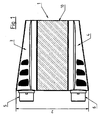
- the structure of the medical separation device (1) as in FIG. 1 . 2 and 2a represented, consisting of a hollow cylindrical housing (2) which is closed at the top and bottom by Genzousendkappen (3, 4), via a fluid inlet (5), a fluid outlet (6) and a filler neck (7) for the filling of medical separation device (1) with the separation medium, which can also be referred to as an adsorbent or stationary phase has, wherein the filler neck (7) tangentially to the, substantially round, in particular cylindrical, bulbous, concave or convex shaped housing (9) medical separation device (1) is mounted.
- a hose line (8) can be coupled in many different ways to the filler neck (7).
- the hose line (8) can be welded, plugged, screwed or pushed onto the filler neck (7).
- the hose line (8) between the container and the device (1) according to the invention can be separated and closed in a suitable length.
- a lateral, tangential arrangement of the filler neck (7), in particular on the inner housing (9), permits a compact and space-saving design.
- the tangential filler neck (7) protrudes from the inner housing (9) by a length of between 0 to 20 mm, preferably 0 to 18 mm, particularly preferably 0 to 16 mm.
- the inner housing (9) itself has a diameter of 3 to 15 cm, preferably 4 to 12 cm, particularly preferably 5 to 10 cm.
- the diameter of the inner housing (9) to the length of the from the inner housing (9) protruding filler neck (7) has a ratio of up to 7.5 / 1, preferably up to 6.7 / 1, more preferably up to 6.25 / 1 on.
- the remainder of the hose line (8) remaining at the filler neck (7) can be laid comfortably around the inner housing (9).
- an inner housing (9) can be preceded by a housing outer wall (10), which also contributes to the compactness and safety of the medical separation device (1) ,
- the distance between the inner housing (9) and the housing outer wall (10) is 2.0 to 10 mm , preferably 3.5 to 8 mm, more preferably 4.5 to 6.8 mm.
- the housing outer wall (10) may be composed of housing outer wall segments or - panels (11).
- the housing outer wall (10) preferably consists of 2, 4 or 6 housing outer wall segments (11), which surround the inner housing (9) of the separating device (1) or are pre-set.
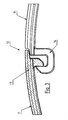
- each housing outer wall segment (11) has a latching mechanism (12), as in FIG. 3 shown, which is preferably located on the outer sides of the housing outer wall segments (11).
- the latching mechanism (12) may be in the form of clip, snap, or hook connections. It goes without saying that each housing outer wall segment (11) has at least one latching element (13) and at least one receiving element (14).
- the inner housing (9) including the filler neck (7) and the hose line (8), by means of a housing outer wall (10), preferably housing outer wall segments (11) to dress, offers the advantage that on the outside of the device (1) according to the invention no radial projecting filling line or cap is no longer present. Should the separator (1) be accidentally dropped once, the filler neck (7) is located behind the housing outer wall (10) and is protected from damage such as breakage or chipping of the filler neck (7) or any part thereof.
- the separation device (1) is further protected against other external destructive influences such as impact.
- the housing outer wall (10), preferably the housing outer wall segments (11), between an upper and lower housing end cap (3, 4) are clamped or locked.
- the housing end caps (3, 4) for receiving the housing outer wall (10), preferably the housing outer wall segments (11), in the form of a circumferential groove or groove (15) are formed. This embodiment can the Figures 2 and 4 be removed.
- the dimensions of the inner housing (9) and the filler neck (7) are to be chosen so that they are smaller together than the radius of the housing end caps (3, 4), so that there is still enough space to a housing outer wall (10) vortex.
- the size of the housing end caps (3, 4) is based on the above-mentioned dimensions of the individual components.
- the housing end caps (3, 4) can be plugged or screwed onto the housing (2), preferably onto the inner housing (9).
- the fluid inlet (5) and the fluid outlet (6) in the housing end caps (3, 4) are preferably arranged radially.
- the separating device (1) is designed such that the radial fluid inlet (5) and the radial fluid outlet (6) point in a predetermined direction, particularly preferably the fluid connections (5, 6) are arranged one above the other.
- the position of the thread start on the housing (2) or on the inner housing (9) and on the housing end caps (3, 4) is decisive.
- the position of the thread start is to be chosen so that the radial fluid inlet (5) and the radial fluid outlet (6) can be brought into a predetermined, preferably in a superposed direction.
- the slip-on device If the housing end caps (3, 4) are plugged onto the housing (2) or the inner housing (9), the slip-on device, according to the knowledge of the skilled person, form such that the alignment of the fluid connections (5, 6) described above are realized can.
- An additional improved safety of the separating device (1) can be achieved in that preferably on the inner housing (9) holding elements (17) for fixing the upper and lower Gezzausendkappen (3, 4) are provided.
- the holding elements (17) may be in the form of clip, snap, or hook connections.
- On the inner housing (9) at least one, preferably two or more holding elements (17) are provided, which are particularly preferably mounted in pairs.
- the holding elements (17) can also be aligned vertically opposite. Opposite the retaining elements (17) are in the housing end caps (3, 4), preferably in the edge region of the housing end caps (3, 4), receiving elements (18) in the form of recesses, depressions or other possible embodiments to the housing end caps (3, 4 ) firmly and securely preferably on the inner housing (9) to fix.
- the embodiment described above has the advantage that the originality of the device is ensured, since the housing end caps (3, 4) can not be removed without destruction of the housing (2) or the inner housing (9) and thus the safety in the application on Patient is increased.
- the radial fluid inlet (5) and the radial fluid drain ( 6) in a predetermined direction, preferably such that the radial fluid inlet (5) and the radial fluid outlet (6) are arranged one above the other.
- Such an embodiment allows a simple assembly and at the same time an improved tightness, since the individual parts of the device (1) experience a uniform bias by the holding mechanism and can connect the individual components of the separator (1) with a high density.
- the invention further relates to a method for producing a housing for a medical separation device (1), preferably an adsorber housing with a filler neck (7) arranged tangentially on the housing, wherein the filler neck (7) preferably laterally on the inner housing (9) of the separation device (1 ) is attached.
- the hollow cylindrical housing (2) is closed with an upper and lower housing end cap (3, 4), wherein the housing end caps (3, 4) are plugged or screwed onto the inner housing (9). That's it Screw thread (16) formed such that both the radial fluid inlet (5) and the radial fluid drain (6) which are arranged in the housing end caps (3, 4) can be aligned in a predetermined direction.
- the housing end caps (3, 4) are mounted so that the radial fluid inlet (5) and the radial fluid outlet (6) are superimposed.
- the housing end caps (3, 4) In order to mount the housing end caps (3, 4) firmly and securely, they are connected to the holding elements (17).
- the housing end caps (3, 4) For fixing the housing end caps (3, 4) at least one, preferably two or more holding elements (17) are provided. It is advantageous in terms of ease of installation, the housing end cap (3, 4) set up so that they can connect with the pairs of the inner housing (9) arranged vertically opposite holding elements (17).
- the housing end caps (3, 4) are locked by the holding elements (17) in the form of a clip, snap or hook connection on the inner housing (9).
- the holding elements (17) are in the housing end caps (3, 4), preferably in the edge region of the housing end caps (3, 4), receiving elements (18) in the form of recesses, depressions or other possible embodiments in which the holding elements (17) can be fitted or snapped.
- the holding elements (17) and receiving elements (18) can be mounted in a particularly preferred embodiment such that the orientation of the radial fluid inlet (5) and the radial fluid outlet (6) in a predetermined direction, in particular such that the radial fluid inlet (5) and the radial fluid drain (6) are arranged one above the other.
- separating elements which are usually screens or nets, which can be applied for stabilization on a support structure and serve to limit the separation medium in a given space and to ensure the best possible fluid distribution.
- a hose line can be mounted on the filler neck (7).
- the hose line (8) in the sense of a simple process management on the filler neck (7) welded, plugged or preferably inserted.
- other variants are conceivable to connect the container in which the separation medium is stored, with the filler neck (7) of the inner housing (9) of the partially manufactured separating device (20).
- the hose line (8) is cut through and sealed in a suitable length.
- the open end of the hose line (8) can be closed with shut-off devices with a clamping device, a plug or in another suitable manner.
- the remaining remainder of the hose line (8), which is still located on the filler neck (7), can now be placed comfortably around the housing inner wall (9).
- the hose length is selected so that it ends before the nearest holding element (17).
- the housing end caps (3, 4) preferably a groove or groove (15) is provided, in which the housing outer wall (10) or the housing outer wall segments (11) can be fitted.
- the housing outer wall (10) is preferably composed of at least two housing outer wall segments or panels (11).
- the individual housing outer wall segments (11) are connected to one another by a latching mechanism (12).
- latching elements (13) and receiving elements (14) in the form of clip, snap, or Hook connections (11) formed.
- Each individual housing outer wall segment (11) is mutually connected both via at least one latching element (13) and via at least one receiving element (14) and fitted into the housing end caps (3, 4) or preferably engaged.
- For stabilization are on the housing outer wall (10) or the housing outer wall segments (11) at regular intervals spacer elements (19) which substantially correspond to the distance between the inner housing (9) and the housing outer wall (10) or the outer wall segments (11).
- the now completely from the housing outer wall (10) or the housing outer wall segments (11) enclosed separation device (1) is finally a sterilization by steam or high-energy, ionizing radiation such as UV, X-ray, alpha, gamma or E-beam radiation if it is intended, for example, as an adsorber for use on the patient.
- ionizing radiation such as UV, X-ray, alpha, gamma or E-beam radiation
- the partially manufactured separating device (20) is designed so that the housing outer wall (10) consists of 2 housing outer wall segments (11), wherein a housing outer wall segment (11) is already pre-assembled, so that after the filling with the separation medium and the welding the hose line (8) only the last housing outer wall segment (11) must be fitted.
- the separating device (1) manufactured in this way is, before use on the patient, subjected to sterilization as described above.
- the separation medium can be stored in a separate compartment or container (21) and connected to the partially manufactured separation device (20) via a hose line (8).
- Both the container (21) filled with the separation medium and the partially manufactured device (26) can first be sterilized together, with the separation medium being able to be transferred into the partially manufactured device (20) at the appropriate time.
- the separation medium can be transferred in a non-sterile environment in the semi-detached separating device (20), since the sterile unit of separator (20) and container (21) remain untouched.
- the housing outer wall (10) or the last housing outer wall segment (11) can also be fitted again here.
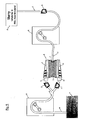
- FIG. 5 By way of example, the filling process of a semi-finished medical separation device (20) is shown.
- the separation medium can be present in a separate compartment or container (21). This is connected via a hose line (8) with the tangentially arranged filler neck (7) on the inner housing (9).
- the adsorber material or separation medium is pumped into the inner housing (9) of the partially manufactured separating device (20) via a pump (22).
- the fluid flow (8) is interrupted and the pump (22) is removed.
- a pump (23) which can be connected via the fluid inlet (5) and / or via the fluid outlet (6) with the inner housing (9), any residual air in the inner housing (9) is removed by the latter through the filler neck ( 7) is pumped out.
- the fluid paths can be opened or closed via the hose clamps (24).
- the hose line (8) is cut at the filler neck (7) in a suitable length and closed.
- the tubing (8) is severed by welding and simultaneously sealed sterile.
- the hose system (25) including the pump (23) with the container (26) is removed.
- the remainder of the hose line (8) remaining on the filler neck (7) is laid around the inner housing (19), preferably to the nearest holding element (17), and the last missing housing outer wall segment (11) is inserted.
- the separating device (1) according to the invention is suitable for use in the technical, preferably analytical, medical and pharmaceutical fields.
- the separation device (1) is used in particular for the depletion of substances from a mixture of substances, preferably for the depletion of peptides or proteins, more preferably of cytokines, low-density lipoproteins (LDL), toxic foreign proteins such as animal toxins. Furthermore, the device (1) is used for the depletion of antibodies, which may be both the body's own as well as foreign to the body, for example, therapeutically effective antibodies.
- the substances to be digested may also be of bacterial origin, both Gram-negative and Gram-positive bacteria such as endotoxins (lipopolysaccharides) or enterotoxins for example Toxic shock syndrome toxin -1 (TSST-1) and (Staphylococcus auraeus) as well as Staphylococcal enterotoxin B ( SEB).
- endotoxins lipopolysaccharides
- enterotoxins for example Toxic shock syndrome toxin -1 (TSST-1) and (Staphylococcus auraeus) as well as Staphylococcal enterotoxin B ( SEB).
- the depletion is particularly preferably carried out from whole blood or blood plasma.
- the separation device (1) consisted of a hollow cylindrical inner housing (9) with a diameter on average of 6.2 cm. On the inner housing (9) tangentially a filling supports (7) for filling the separation device (1) with the separation medium or adsorbent was arranged. The filler neck (7) protruded with a length of 16.5 mm out of the inner housing (9). To fill the separator, a hose line (8) was inserted into the filler neck (7). On the inner housing (9) were further pairwise two vertically opposed holding elements (17) mounted in the form of snap connections, for locking the Genzousendkappen (3, 4) and for aligning the radial fluid inlet (5) and the radial fluid drain (6) in a served one above the other arranged direction.
- receiving elements (18) for the holding elements (17) were mounted in the housing end caps (3, 4).
- the severed and welded hose line (8) reached from its maximum length to the opposite holding elements (17).
- the inner housing (9) and the hose line (8) were enclosed by two housing outer wall segments (11).
- the two Housing outer wall segments (11) were interconnected via a latching mechanism (12) in the form of a snap connection, each housing outer wall segment (11) having a latching element (13) and a receiving element (14).
- Between the inner housing (9) and the housing outer wall segments (11) was a distance of 6.4 mm.
- To stabilize the housing outer wall segments (11) were mounted on the inside of spacer elements, which corresponded substantially to the distance between the inner housing (9) and the housing outer wall segments (11).
Landscapes
- Health & Medical Sciences (AREA)
- Chemical & Material Sciences (AREA)
- Analytical Chemistry (AREA)
- Vascular Medicine (AREA)
- Heart & Thoracic Surgery (AREA)
- Chemical Kinetics & Catalysis (AREA)
- Life Sciences & Earth Sciences (AREA)
- General Health & Medical Sciences (AREA)
- Anesthesiology (AREA)
- Biomedical Technology (AREA)
- Veterinary Medicine (AREA)
- Cardiology (AREA)
- Public Health (AREA)
- Animal Behavior & Ethology (AREA)
- Engineering & Computer Science (AREA)
- Hematology (AREA)
- General Physics & Mathematics (AREA)
- Physics & Mathematics (AREA)
- Biochemistry (AREA)
- Immunology (AREA)
- Pathology (AREA)
- External Artificial Organs (AREA)
- Treatment Of Liquids With Adsorbents In General (AREA)
Priority Applications (1)
| Application Number | Priority Date | Filing Date | Title |
|---|---|---|---|
| PL11771037T PL2632507T3 (pl) | 2010-10-29 | 2011-10-18 | Medyczne urządzenie frakcjonujące |
Applications Claiming Priority (2)
| Application Number | Priority Date | Filing Date | Title |
|---|---|---|---|
| DE102010049790A DE102010049790A1 (de) | 2010-10-29 | 2010-10-29 | Medizinische Trennvorrichtung |
| PCT/EP2011/005218 WO2012055500A1 (de) | 2010-10-29 | 2011-10-18 | Medizinische trennvorrichtung |
Publications (2)
| Publication Number | Publication Date |
|---|---|
| EP2632507A1 EP2632507A1 (de) | 2013-09-04 |
| EP2632507B1 true EP2632507B1 (de) | 2014-09-24 |
Family
ID=44872274
Family Applications (1)
| Application Number | Title | Priority Date | Filing Date |
|---|---|---|---|
| EP11771037.6A Active EP2632507B1 (de) | 2010-10-29 | 2011-10-18 | Medizinische trennvorrichtung |
Country Status (8)
| Country | Link |
|---|---|
| US (1) | US9782531B2 (pl) |
| EP (1) | EP2632507B1 (pl) |
| JP (1) | JP5886861B2 (pl) |
| CN (1) | CN103298502B (pl) |
| DE (1) | DE102010049790A1 (pl) |
| ES (1) | ES2522556T3 (pl) |
| PL (1) | PL2632507T3 (pl) |
| WO (1) | WO2012055500A1 (pl) |
Families Citing this family (1)
| Publication number | Priority date | Publication date | Assignee | Title |
|---|---|---|---|---|
| JP7429343B2 (ja) | 2018-01-05 | 2024-02-08 | パス イーエックス,インク. | 流体からの疾患材料の捕捉および除去のためのデバイス |
Family Cites Families (23)
| Publication number | Priority date | Publication date | Assignee | Title |
|---|---|---|---|---|
| US3459307A (en) * | 1967-10-11 | 1969-08-05 | Henry R Collins Jr | Small particle bypass filter means |
| JPS5819324B2 (ja) * | 1976-11-12 | 1983-04-18 | 三菱電機株式会社 | 吸着処理装置 |
| US4247987A (en) * | 1979-09-26 | 1981-02-03 | Exxon Research & Engineering Co. | Continuous countercurrent fluid-solids contacting process stabilized by a magnetic field |
| EP0106419A3 (en) * | 1982-09-11 | 1986-03-26 | Whatman Reeve Angel Plc | Chromatographic column |
| GB8413121D0 (en) | 1984-05-23 | 1984-06-27 | Weaver V C | Preparative columns for chromatography |
| GB8524599D0 (en) | 1985-10-04 | 1985-11-06 | Boc Group Plc | Adsorbers |
| US4627918A (en) * | 1985-11-04 | 1986-12-09 | Sepragen Corporation | Chromatography column using horizontal flow |
| JPH0729004B2 (ja) * | 1988-02-01 | 1995-04-05 | 富士写真フイルム株式会社 | 止め弁付フイルタ装置 |
| US4927536A (en) * | 1989-03-21 | 1990-05-22 | Amoco Corporation | Hydrocyclone separation system |
| DE8915876U1 (de) * | 1989-08-11 | 1992-02-27 | Gräff, Roderich W., Dr.-Ing., 6108 Weiterstadt | Vorrichtung zur Adsorption von Feuchtigkeit o.dgl. Stoffen aus einem Gasstrom |
| DE4110730A1 (de) * | 1991-04-03 | 1992-10-15 | Fresenius Ag | Vorrichtung zur auftrennung von zumindest zwei biologischen stoffen in loesung durch adsorption |
| DE19540431C1 (de) * | 1995-10-30 | 1997-07-24 | Franck Hans P | Adsorptionssäule |
| US6878269B2 (en) * | 1996-01-31 | 2005-04-12 | Kaneka Corporation | Device for body fluid purification and system for body fluid purification |
| US5667676A (en) * | 1996-05-01 | 1997-09-16 | Alaska; Andrew B. | Side-packed chromatographic column |
| US7014049B2 (en) * | 1996-12-23 | 2006-03-21 | Glycorex Transplantation Ab | Device for bio-affinity material |
| SI1049499T1 (en) * | 1998-01-20 | 2004-04-30 | Mitra Medical Technology Ab | An apparatus for use in connection with removal of elements, especially exogenous antibodies, from blood or plasma |
| JP4643830B2 (ja) | 1999-03-17 | 2011-03-02 | 株式会社Jimro | 疾患の処置 |
| EP1396721B1 (en) * | 2001-05-18 | 2008-08-06 | Northwest University | A caky chromatographic column and the method for producing it and its applications |
| DE102006058955B4 (de) * | 2006-12-12 | 2014-07-24 | DüRR DENTAL AG | Saugvorrichtung für dentale, medizinische und industrielle Zwecke |
| GB0704603D0 (en) * | 2007-03-09 | 2007-04-18 | Ge Healthcare Bio Sciences Ab | Packing system and method for chromatography columns |
| US20090321338A1 (en) | 2008-06-25 | 2009-12-31 | Millipore Corporation | Chromatography apparatus |
| DE102008053131A1 (de) * | 2008-10-24 | 2010-04-29 | Fresenius Medical Care Deutschland Gmbh | Verfahren und Anordnung zum Sterilisieren, insbesondere zum Sterilisieren eines Adsorbers |
| GB2467207A (en) * | 2009-01-26 | 2010-07-28 | Agilent Technologies Inc | Separation device with moveable filing channel |
-
2010
- 2010-10-29 DE DE102010049790A patent/DE102010049790A1/de not_active Withdrawn
-
2011
- 2011-10-18 JP JP2013535299A patent/JP5886861B2/ja not_active Expired - Fee Related
- 2011-10-18 EP EP11771037.6A patent/EP2632507B1/de active Active
- 2011-10-18 PL PL11771037T patent/PL2632507T3/pl unknown
- 2011-10-18 CN CN201180052961.1A patent/CN103298502B/zh not_active Expired - Fee Related
- 2011-10-18 ES ES11771037.6T patent/ES2522556T3/es active Active
- 2011-10-18 WO PCT/EP2011/005218 patent/WO2012055500A1/de not_active Ceased
- 2011-10-18 US US13/881,841 patent/US9782531B2/en not_active Expired - Fee Related
Also Published As
| Publication number | Publication date |
|---|---|
| US9782531B2 (en) | 2017-10-10 |
| CN103298502A (zh) | 2013-09-11 |
| EP2632507A1 (de) | 2013-09-04 |
| US20130270198A1 (en) | 2013-10-17 |
| CN103298502B (zh) | 2017-04-26 |
| JP5886861B2 (ja) | 2016-03-16 |
| WO2012055500A1 (de) | 2012-05-03 |
| ES2522556T3 (es) | 2014-11-17 |
| PL2632507T3 (pl) | 2015-03-31 |
| DE102010049790A1 (de) | 2012-05-03 |
| JP2014503339A (ja) | 2014-02-13 |
Similar Documents
| Publication | Publication Date | Title |
|---|---|---|
| EP2965767B1 (de) | Verfahren zur sterilisierung eines hohlfaserfiltermoduls, hohlfaserfiltermodul mit verschluss und verwendung eines sauerstoff- absorbierenden verschlusses | |
| EP3341106B1 (de) | Einweg-filtrationsvorrichtung | |
| EP2833948B1 (de) | Verschlusssystem für einen applikationseinrichtungsansatz an einem behälter für pharmazeutische präparate, und verwendung, behälter mit verschlusssystem, spritze für medizinische zwecke und verfahren zur montage | |
| DE8817024U1 (de) | Gasdichte Verschlußvorrichtung für die Verbindungsenden von Röhren für biomedizinische Flüssigkeitstransporteinrichtungen insbesondere haemodialytische Ketten, welche mittels Sterilisationsgas sterilisiert sind | |
| EP2818152B1 (de) | Luer-Lock-Verbinder mit Nuten | |
| DE102011116520A1 (de) | Luftfilterpatrone zur Druckluftaufbereitung für eine Druckluftaufbereitungsanlage | |
| EP2877219A1 (de) | Mobiles system zur mittels schwerkraft erfolgenden aufteilung von spenderblut | |
| EP3921013B1 (de) | Sterilverbinder für den sterilen transfer eines flüssigen mediums | |
| EP2736586B1 (de) | Medizinischer schlauch sowie verfahren zum sterilisieren eines medizinischen schlauchs | |
| WO2010140063A2 (de) | Vorrichtung zur applikation fluidaler medikamente | |
| EP4331711A1 (de) | Einweg-filtercapsule fur eine filtrationsvorrichtung | |
| EP3241806B1 (de) | Endständige filtervorrichtung zur reduktion von mikrobiologischen verunreinigungen in einem wässrigen medium | |
| WO2012055500A1 (de) | Medizinische trennvorrichtung | |
| EP3846873A1 (de) | Behälteranordnung und verfahren zur befüllung derselben | |
| DE69426384T2 (de) | System zum füllen eines anästhetischen zerstäubers | |
| EP2633307B1 (de) | Vorrichtung zur chromatographischen auftrennung eines stoffgemisches und deren verwendung | |
| EP3755397B1 (de) | Vorrichtung enthaltend dialyselösung oder dialyselösungskonzentrat | |
| EP2649937B1 (de) | Vorrichtung zur Ent- und/oder Aufnahme von Körperflüssigkeiten, insbesondere Blut | |
| DE102008046836B4 (de) | Speichertanksystem mit Absperrvorrichtung | |
| EP4243882B1 (de) | Verfahren zur sicherstellung einer mikrobiologischen reinheit einer einweg-vorrichtung | |
| DE102021131267A1 (de) | Verschlusskappe für Flüssigkeitsanschlüsse eines Dialysators | |
| DE102022131808A1 (de) | Funktionselement, Beta-Behältersystem, Transfersystem und Barrieresystem | |
| DE202019100337U1 (de) | Vorrichtung zur Be- oder Nachfüllung der Gasvorlage in Membranausdehnungsgefäßen an Heizungs- oder Wasserversorgungsanlagen | |
| EP3628365A1 (de) | Verbindungsvorrichtung für die wundversorgung und wundversorgungskit | |
| DE20220044U1 (de) | Elektrolytumwälzeinrichtung für Bleiakkumulatoren |
Legal Events
| Date | Code | Title | Description |
|---|---|---|---|
| PUAI | Public reference made under article 153(3) epc to a published international application that has entered the european phase |
Free format text: ORIGINAL CODE: 0009012 |
|
| 17P | Request for examination filed |
Effective date: 20130529 |
|
| AK | Designated contracting states |
Kind code of ref document: A1 Designated state(s): AL AT BE BG CH CY CZ DE DK EE ES FI FR GB GR HR HU IE IS IT LI LT LU LV MC MK MT NL NO PL PT RO RS SE SI SK SM TR |
|
| DAX | Request for extension of the european patent (deleted) | ||
| GRAP | Despatch of communication of intention to grant a patent |
Free format text: ORIGINAL CODE: EPIDOSNIGR1 |
|
| INTG | Intention to grant announced |
Effective date: 20140613 |
|
| GRAS | Grant fee paid |
Free format text: ORIGINAL CODE: EPIDOSNIGR3 |
|
| GRAA | (expected) grant |
Free format text: ORIGINAL CODE: 0009210 |
|
| AK | Designated contracting states |
Kind code of ref document: B1 Designated state(s): AL AT BE BG CH CY CZ DE DK EE ES FI FR GB GR HR HU IE IS IT LI LT LU LV MC MK MT NL NO PL PT RO RS SE SI SK SM TR |
|
| REG | Reference to a national code |
Ref country code: GB Ref legal event code: FG4D Free format text: NOT ENGLISH |
|
| REG | Reference to a national code |
Ref country code: CH Ref legal event code: EP |
|
| REG | Reference to a national code |
Ref country code: AT Ref legal event code: REF Ref document number: 688319 Country of ref document: AT Kind code of ref document: T Effective date: 20141015 |
|
| REG | Reference to a national code |
Ref country code: IE Ref legal event code: FG4D Free format text: LANGUAGE OF EP DOCUMENT: GERMAN |
|
| REG | Reference to a national code |
Ref country code: DE Ref legal event code: R096 Ref document number: 502011004475 Country of ref document: DE Effective date: 20141106 |
|
| REG | Reference to a national code |
Ref country code: CH Ref legal event code: NV Representative=s name: DTS ZUERICH, CH |
|
| REG | Reference to a national code |
Ref country code: ES Ref legal event code: FG2A Ref document number: 2522556 Country of ref document: ES Kind code of ref document: T3 Effective date: 20141117 |
|
| REG | Reference to a national code |
Ref country code: SE Ref legal event code: TRGR |
|
| PG25 | Lapsed in a contracting state [announced via postgrant information from national office to epo] |
Ref country code: NO Free format text: LAPSE BECAUSE OF FAILURE TO SUBMIT A TRANSLATION OF THE DESCRIPTION OR TO PAY THE FEE WITHIN THE PRESCRIBED TIME-LIMIT Effective date: 20141224 Ref country code: GR Free format text: LAPSE BECAUSE OF FAILURE TO SUBMIT A TRANSLATION OF THE DESCRIPTION OR TO PAY THE FEE WITHIN THE PRESCRIBED TIME-LIMIT Effective date: 20141225 Ref country code: LT Free format text: LAPSE BECAUSE OF FAILURE TO SUBMIT A TRANSLATION OF THE DESCRIPTION OR TO PAY THE FEE WITHIN THE PRESCRIBED TIME-LIMIT Effective date: 20140924 Ref country code: FI Free format text: LAPSE BECAUSE OF FAILURE TO SUBMIT A TRANSLATION OF THE DESCRIPTION OR TO PAY THE FEE WITHIN THE PRESCRIBED TIME-LIMIT Effective date: 20140924 |
|
| REG | Reference to a national code |
Ref country code: LT Ref legal event code: MG4D Ref country code: NL Ref legal event code: VDEP Effective date: 20140924 |
|
| PG25 | Lapsed in a contracting state [announced via postgrant information from national office to epo] |
Ref country code: RS Free format text: LAPSE BECAUSE OF FAILURE TO SUBMIT A TRANSLATION OF THE DESCRIPTION OR TO PAY THE FEE WITHIN THE PRESCRIBED TIME-LIMIT Effective date: 20140924 Ref country code: LV Free format text: LAPSE BECAUSE OF FAILURE TO SUBMIT A TRANSLATION OF THE DESCRIPTION OR TO PAY THE FEE WITHIN THE PRESCRIBED TIME-LIMIT Effective date: 20140924 Ref country code: HR Free format text: LAPSE BECAUSE OF FAILURE TO SUBMIT A TRANSLATION OF THE DESCRIPTION OR TO PAY THE FEE WITHIN THE PRESCRIBED TIME-LIMIT Effective date: 20140924 Ref country code: CY Free format text: LAPSE BECAUSE OF FAILURE TO SUBMIT A TRANSLATION OF THE DESCRIPTION OR TO PAY THE FEE WITHIN THE PRESCRIBED TIME-LIMIT Effective date: 20140924 |
|
| PG25 | Lapsed in a contracting state [announced via postgrant information from national office to epo] |
Ref country code: NL Free format text: LAPSE BECAUSE OF FAILURE TO SUBMIT A TRANSLATION OF THE DESCRIPTION OR TO PAY THE FEE WITHIN THE PRESCRIBED TIME-LIMIT Effective date: 20140924 |
|
| REG | Reference to a national code |
Ref country code: PL Ref legal event code: T3 |
|
| PG25 | Lapsed in a contracting state [announced via postgrant information from national office to epo] |
Ref country code: SK Free format text: LAPSE BECAUSE OF FAILURE TO SUBMIT A TRANSLATION OF THE DESCRIPTION OR TO PAY THE FEE WITHIN THE PRESCRIBED TIME-LIMIT Effective date: 20140924 Ref country code: IS Free format text: LAPSE BECAUSE OF FAILURE TO SUBMIT A TRANSLATION OF THE DESCRIPTION OR TO PAY THE FEE WITHIN THE PRESCRIBED TIME-LIMIT Effective date: 20150124 Ref country code: PT Free format text: LAPSE BECAUSE OF FAILURE TO SUBMIT A TRANSLATION OF THE DESCRIPTION OR TO PAY THE FEE WITHIN THE PRESCRIBED TIME-LIMIT Effective date: 20150126 Ref country code: EE Free format text: LAPSE BECAUSE OF FAILURE TO SUBMIT A TRANSLATION OF THE DESCRIPTION OR TO PAY THE FEE WITHIN THE PRESCRIBED TIME-LIMIT Effective date: 20140924 Ref country code: RO Free format text: LAPSE BECAUSE OF FAILURE TO SUBMIT A TRANSLATION OF THE DESCRIPTION OR TO PAY THE FEE WITHIN THE PRESCRIBED TIME-LIMIT Effective date: 20140924 |
|
| REG | Reference to a national code |
Ref country code: DE Ref legal event code: R097 Ref document number: 502011004475 Country of ref document: DE |
|
| PG25 | Lapsed in a contracting state [announced via postgrant information from national office to epo] |
Ref country code: BE Free format text: LAPSE BECAUSE OF NON-PAYMENT OF DUE FEES Effective date: 20141031 Ref country code: MC Free format text: LAPSE BECAUSE OF FAILURE TO SUBMIT A TRANSLATION OF THE DESCRIPTION OR TO PAY THE FEE WITHIN THE PRESCRIBED TIME-LIMIT Effective date: 20140924 |
|
| REG | Reference to a national code |
Ref country code: IE Ref legal event code: MM4A |
|
| PG25 | Lapsed in a contracting state [announced via postgrant information from national office to epo] |
Ref country code: DK Free format text: LAPSE BECAUSE OF FAILURE TO SUBMIT A TRANSLATION OF THE DESCRIPTION OR TO PAY THE FEE WITHIN THE PRESCRIBED TIME-LIMIT Effective date: 20140924 |
|
| PLBE | No opposition filed within time limit |
Free format text: ORIGINAL CODE: 0009261 |
|
| STAA | Information on the status of an ep patent application or granted ep patent |
Free format text: STATUS: NO OPPOSITION FILED WITHIN TIME LIMIT |
|
| 26N | No opposition filed |
Effective date: 20150625 |
|
| PG25 | Lapsed in a contracting state [announced via postgrant information from national office to epo] |
Ref country code: IE Free format text: LAPSE BECAUSE OF NON-PAYMENT OF DUE FEES Effective date: 20141018 |
|
| PG25 | Lapsed in a contracting state [announced via postgrant information from national office to epo] |
Ref country code: SI Free format text: LAPSE BECAUSE OF FAILURE TO SUBMIT A TRANSLATION OF THE DESCRIPTION OR TO PAY THE FEE WITHIN THE PRESCRIBED TIME-LIMIT Effective date: 20140924 |
|
| PG25 | Lapsed in a contracting state [announced via postgrant information from national office to epo] |
Ref country code: SM Free format text: LAPSE BECAUSE OF FAILURE TO SUBMIT A TRANSLATION OF THE DESCRIPTION OR TO PAY THE FEE WITHIN THE PRESCRIBED TIME-LIMIT Effective date: 20140924 |
|
| PG25 | Lapsed in a contracting state [announced via postgrant information from national office to epo] |
Ref country code: BG Free format text: LAPSE BECAUSE OF FAILURE TO SUBMIT A TRANSLATION OF THE DESCRIPTION OR TO PAY THE FEE WITHIN THE PRESCRIBED TIME-LIMIT Effective date: 20140924 |
|
| PG25 | Lapsed in a contracting state [announced via postgrant information from national office to epo] |
Ref country code: TR Free format text: LAPSE BECAUSE OF FAILURE TO SUBMIT A TRANSLATION OF THE DESCRIPTION OR TO PAY THE FEE WITHIN THE PRESCRIBED TIME-LIMIT Effective date: 20140924 Ref country code: MT Free format text: LAPSE BECAUSE OF FAILURE TO SUBMIT A TRANSLATION OF THE DESCRIPTION OR TO PAY THE FEE WITHIN THE PRESCRIBED TIME-LIMIT Effective date: 20140924 Ref country code: HU Free format text: LAPSE BECAUSE OF FAILURE TO SUBMIT A TRANSLATION OF THE DESCRIPTION OR TO PAY THE FEE WITHIN THE PRESCRIBED TIME-LIMIT; INVALID AB INITIO Effective date: 20111018 Ref country code: LU Free format text: LAPSE BECAUSE OF NON-PAYMENT OF DUE FEES Effective date: 20141018 |
|
| REG | Reference to a national code |
Ref country code: FR Ref legal event code: PLFP Year of fee payment: 6 |
|
| REG | Reference to a national code |
Ref country code: FR Ref legal event code: PLFP Year of fee payment: 7 |
|
| PG25 | Lapsed in a contracting state [announced via postgrant information from national office to epo] |
Ref country code: MK Free format text: LAPSE BECAUSE OF FAILURE TO SUBMIT A TRANSLATION OF THE DESCRIPTION OR TO PAY THE FEE WITHIN THE PRESCRIBED TIME-LIMIT Effective date: 20140924 |
|
| REG | Reference to a national code |
Ref country code: FR Ref legal event code: PLFP Year of fee payment: 8 |
|
| PG25 | Lapsed in a contracting state [announced via postgrant information from national office to epo] |
Ref country code: AL Free format text: LAPSE BECAUSE OF FAILURE TO SUBMIT A TRANSLATION OF THE DESCRIPTION OR TO PAY THE FEE WITHIN THE PRESCRIBED TIME-LIMIT Effective date: 20140924 |
|
| REG | Reference to a national code |
Ref country code: CH Ref legal event code: PCAR Free format text: NEW ADDRESS: BADSTRASSE 5 POSTFACH, 8501 FRAUENFELD (CH) |
|
| REG | Reference to a national code |
Ref country code: CH Ref legal event code: PCAR Free format text: NEW ADDRESS: BAHNHOFSTRASSE 100, 8001 ZUERICH (CH) |
|
| P01 | Opt-out of the competence of the unified patent court (upc) registered |
Effective date: 20230602 |
|
| PGFP | Annual fee paid to national office [announced via postgrant information from national office to epo] |
Ref country code: IT Payment date: 20230920 Year of fee payment: 13 Ref country code: GB Payment date: 20230920 Year of fee payment: 13 Ref country code: CZ Payment date: 20230926 Year of fee payment: 13 |
|
| PGFP | Annual fee paid to national office [announced via postgrant information from national office to epo] |
Ref country code: SE Payment date: 20230922 Year of fee payment: 13 Ref country code: PL Payment date: 20230925 Year of fee payment: 13 Ref country code: FR Payment date: 20230920 Year of fee payment: 13 |
|
| PGFP | Annual fee paid to national office [announced via postgrant information from national office to epo] |
Ref country code: ES Payment date: 20231102 Year of fee payment: 13 |
|
| PGFP | Annual fee paid to national office [announced via postgrant information from national office to epo] |
Ref country code: DE Payment date: 20231031 Year of fee payment: 13 Ref country code: CH Payment date: 20231102 Year of fee payment: 13 Ref country code: AT Payment date: 20230921 Year of fee payment: 13 |
|
| REG | Reference to a national code |
Ref country code: DE Ref legal event code: R119 Ref document number: 502011004475 Country of ref document: DE |
|
| REG | Reference to a national code |
Ref country code: CH Ref legal event code: PL |
|
| REG | Reference to a national code |
Ref country code: SE Ref legal event code: EUG |
|
| REG | Reference to a national code |
Ref country code: AT Ref legal event code: MM01 Ref document number: 688319 Country of ref document: AT Kind code of ref document: T Effective date: 20241018 |
|
| GBPC | Gb: european patent ceased through non-payment of renewal fee |
Effective date: 20241018 |
|
| PG25 | Lapsed in a contracting state [announced via postgrant information from national office to epo] |
Ref country code: DE Free format text: LAPSE BECAUSE OF NON-PAYMENT OF DUE FEES Effective date: 20250501 |
|
| PG25 | Lapsed in a contracting state [announced via postgrant information from national office to epo] |
Ref country code: GB Free format text: LAPSE BECAUSE OF NON-PAYMENT OF DUE FEES Effective date: 20241018 |
|
| PG25 | Lapsed in a contracting state [announced via postgrant information from national office to epo] |
Ref country code: FR Free format text: LAPSE BECAUSE OF NON-PAYMENT OF DUE FEES Effective date: 20241031 |
|
| PG25 | Lapsed in a contracting state [announced via postgrant information from national office to epo] |
Ref country code: CH Free format text: LAPSE BECAUSE OF NON-PAYMENT OF DUE FEES Effective date: 20241031 |
|
| PG25 | Lapsed in a contracting state [announced via postgrant information from national office to epo] |
Ref country code: AT Free format text: LAPSE BECAUSE OF NON-PAYMENT OF DUE FEES Effective date: 20241018 |
|
| PG25 | Lapsed in a contracting state [announced via postgrant information from national office to epo] |
Ref country code: CZ Free format text: LAPSE BECAUSE OF NON-PAYMENT OF DUE FEES Effective date: 20241018 |
|
| PG25 | Lapsed in a contracting state [announced via postgrant information from national office to epo] |
Ref country code: SE Free format text: LAPSE BECAUSE OF NON-PAYMENT OF DUE FEES Effective date: 20241019 Ref country code: IT Free format text: LAPSE BECAUSE OF NON-PAYMENT OF DUE FEES Effective date: 20241018 |
|
| REG | Reference to a national code |
Ref country code: ES Ref legal event code: FD2A Effective date: 20251201 |
|
| PG25 | Lapsed in a contracting state [announced via postgrant information from national office to epo] |
Ref country code: ES Free format text: LAPSE BECAUSE OF NON-PAYMENT OF DUE FEES Effective date: 20241019 |
|
| PG25 | Lapsed in a contracting state [announced via postgrant information from national office to epo] |
Ref country code: PL Free format text: LAPSE BECAUSE OF NON-PAYMENT OF DUE FEES Effective date: 20241018 |