EP2632781B1 - Système de freinage pour un véhicule - Google Patents
Système de freinage pour un véhicule Download PDFInfo
- Publication number
- EP2632781B1 EP2632781B1 EP11751898.5A EP11751898A EP2632781B1 EP 2632781 B1 EP2632781 B1 EP 2632781B1 EP 11751898 A EP11751898 A EP 11751898A EP 2632781 B1 EP2632781 B1 EP 2632781B1
- Authority
- EP
- European Patent Office
- Prior art keywords
- brake
- valve
- wheel
- master
- cylinder
- Prior art date
- Legal status (The legal status is an assumption and is not a legal conclusion. Google has not performed a legal analysis and makes no representation as to the accuracy of the status listed.)
- Active
Links
Images


Classifications
-
- B—PERFORMING OPERATIONS; TRANSPORTING
- B60—VEHICLES IN GENERAL
- B60T—VEHICLE BRAKE CONTROL SYSTEMS OR PARTS THEREOF; BRAKE CONTROL SYSTEMS OR PARTS THEREOF, IN GENERAL; ARRANGEMENT OF BRAKING ELEMENTS ON VEHICLES IN GENERAL; PORTABLE DEVICES FOR PREVENTING UNWANTED MOVEMENT OF VEHICLES; VEHICLE MODIFICATIONS TO FACILITATE COOLING OF BRAKES
- B60T8/00—Arrangements for adjusting wheel-braking force to meet varying vehicular or ground-surface conditions, e.g. limiting or varying distribution of braking force
- B60T8/32—Arrangements for adjusting wheel-braking force to meet varying vehicular or ground-surface conditions, e.g. limiting or varying distribution of braking force responsive to a speed condition, e.g. acceleration or deceleration
- B60T8/34—Arrangements for adjusting wheel-braking force to meet varying vehicular or ground-surface conditions, e.g. limiting or varying distribution of braking force responsive to a speed condition, e.g. acceleration or deceleration having a fluid pressure regulator responsive to a speed condition
- B60T8/48—Arrangements for adjusting wheel-braking force to meet varying vehicular or ground-surface conditions, e.g. limiting or varying distribution of braking force responsive to a speed condition, e.g. acceleration or deceleration having a fluid pressure regulator responsive to a speed condition connecting the brake actuator to an alternative or additional source of fluid pressure, e.g. traction control systems
-
- B—PERFORMING OPERATIONS; TRANSPORTING
- B60—VEHICLES IN GENERAL
- B60T—VEHICLE BRAKE CONTROL SYSTEMS OR PARTS THEREOF; BRAKE CONTROL SYSTEMS OR PARTS THEREOF, IN GENERAL; ARRANGEMENT OF BRAKING ELEMENTS ON VEHICLES IN GENERAL; PORTABLE DEVICES FOR PREVENTING UNWANTED MOVEMENT OF VEHICLES; VEHICLE MODIFICATIONS TO FACILITATE COOLING OF BRAKES
- B60T13/00—Transmitting braking action from initiating means to ultimate brake actuator with power assistance or drive; Brake systems incorporating such transmitting means, e.g. air-pressure brake systems
- B60T13/10—Transmitting braking action from initiating means to ultimate brake actuator with power assistance or drive; Brake systems incorporating such transmitting means, e.g. air-pressure brake systems with fluid assistance, drive, or release
- B60T13/66—Electrical control in fluid-pressure brake systems
- B60T13/68—Electrical control in fluid-pressure brake systems by electrically-controlled valves
- B60T13/686—Electrical control in fluid-pressure brake systems by electrically-controlled valves in hydraulic systems or parts thereof
-
- B—PERFORMING OPERATIONS; TRANSPORTING
- B60—VEHICLES IN GENERAL
- B60T—VEHICLE BRAKE CONTROL SYSTEMS OR PARTS THEREOF; BRAKE CONTROL SYSTEMS OR PARTS THEREOF, IN GENERAL; ARRANGEMENT OF BRAKING ELEMENTS ON VEHICLES IN GENERAL; PORTABLE DEVICES FOR PREVENTING UNWANTED MOVEMENT OF VEHICLES; VEHICLE MODIFICATIONS TO FACILITATE COOLING OF BRAKES
- B60T11/00—Transmitting braking action from initiating means to ultimate brake actuator without power assistance or drive or where such assistance or drive is irrelevant
- B60T11/10—Transmitting braking action from initiating means to ultimate brake actuator without power assistance or drive or where such assistance or drive is irrelevant transmitting by fluid means, e.g. hydraulic
- B60T11/16—Master control, e.g. master cylinders
- B60T11/232—Recuperation valves
-
- B—PERFORMING OPERATIONS; TRANSPORTING
- B60—VEHICLES IN GENERAL
- B60T—VEHICLE BRAKE CONTROL SYSTEMS OR PARTS THEREOF; BRAKE CONTROL SYSTEMS OR PARTS THEREOF, IN GENERAL; ARRANGEMENT OF BRAKING ELEMENTS ON VEHICLES IN GENERAL; PORTABLE DEVICES FOR PREVENTING UNWANTED MOVEMENT OF VEHICLES; VEHICLE MODIFICATIONS TO FACILITATE COOLING OF BRAKES
- B60T13/00—Transmitting braking action from initiating means to ultimate brake actuator with power assistance or drive; Brake systems incorporating such transmitting means, e.g. air-pressure brake systems
- B60T13/10—Transmitting braking action from initiating means to ultimate brake actuator with power assistance or drive; Brake systems incorporating such transmitting means, e.g. air-pressure brake systems with fluid assistance, drive, or release
- B60T13/12—Transmitting braking action from initiating means to ultimate brake actuator with power assistance or drive; Brake systems incorporating such transmitting means, e.g. air-pressure brake systems with fluid assistance, drive, or release the fluid being liquid
- B60T13/14—Transmitting braking action from initiating means to ultimate brake actuator with power assistance or drive; Brake systems incorporating such transmitting means, e.g. air-pressure brake systems with fluid assistance, drive, or release the fluid being liquid using accumulators or reservoirs fed by pumps
- B60T13/142—Systems with master cylinder
-
- B—PERFORMING OPERATIONS; TRANSPORTING
- B60—VEHICLES IN GENERAL
- B60T—VEHICLE BRAKE CONTROL SYSTEMS OR PARTS THEREOF; BRAKE CONTROL SYSTEMS OR PARTS THEREOF, IN GENERAL; ARRANGEMENT OF BRAKING ELEMENTS ON VEHICLES IN GENERAL; PORTABLE DEVICES FOR PREVENTING UNWANTED MOVEMENT OF VEHICLES; VEHICLE MODIFICATIONS TO FACILITATE COOLING OF BRAKES
- B60T17/00—Component parts, details, or accessories of power brake systems not covered by groups B60T8/00, B60T13/00 or B60T15/00, or presenting other characteristic features
- B60T17/04—Arrangements of piping, valves in the piping, e.g. cut-off valves, couplings or air hoses
-
- B—PERFORMING OPERATIONS; TRANSPORTING
- B60—VEHICLES IN GENERAL
- B60T—VEHICLE BRAKE CONTROL SYSTEMS OR PARTS THEREOF; BRAKE CONTROL SYSTEMS OR PARTS THEREOF, IN GENERAL; ARRANGEMENT OF BRAKING ELEMENTS ON VEHICLES IN GENERAL; PORTABLE DEVICES FOR PREVENTING UNWANTED MOVEMENT OF VEHICLES; VEHICLE MODIFICATIONS TO FACILITATE COOLING OF BRAKES
- B60T8/00—Arrangements for adjusting wheel-braking force to meet varying vehicular or ground-surface conditions, e.g. limiting or varying distribution of braking force
- B60T8/24—Arrangements for adjusting wheel-braking force to meet varying vehicular or ground-surface conditions, e.g. limiting or varying distribution of braking force responsive to vehicle inclination or change of direction, e.g. negotiating bends
- B60T8/246—Change of direction
-
- B—PERFORMING OPERATIONS; TRANSPORTING
- B60—VEHICLES IN GENERAL
- B60T—VEHICLE BRAKE CONTROL SYSTEMS OR PARTS THEREOF; BRAKE CONTROL SYSTEMS OR PARTS THEREOF, IN GENERAL; ARRANGEMENT OF BRAKING ELEMENTS ON VEHICLES IN GENERAL; PORTABLE DEVICES FOR PREVENTING UNWANTED MOVEMENT OF VEHICLES; VEHICLE MODIFICATIONS TO FACILITATE COOLING OF BRAKES
- B60T8/00—Arrangements for adjusting wheel-braking force to meet varying vehicular or ground-surface conditions, e.g. limiting or varying distribution of braking force
- B60T8/26—Arrangements for adjusting wheel-braking force to meet varying vehicular or ground-surface conditions, e.g. limiting or varying distribution of braking force characterised by producing differential braking between front and rear wheels
- B60T8/266—Arrangements for adjusting wheel-braking force to meet varying vehicular or ground-surface conditions, e.g. limiting or varying distribution of braking force characterised by producing differential braking between front and rear wheels using valves or actuators with external control means
- B60T8/267—Arrangements for adjusting wheel-braking force to meet varying vehicular or ground-surface conditions, e.g. limiting or varying distribution of braking force characterised by producing differential braking between front and rear wheels using valves or actuators with external control means for hybrid systems with different kind of brakes on different axles
-
- B—PERFORMING OPERATIONS; TRANSPORTING
- B60—VEHICLES IN GENERAL
- B60T—VEHICLE BRAKE CONTROL SYSTEMS OR PARTS THEREOF; BRAKE CONTROL SYSTEMS OR PARTS THEREOF, IN GENERAL; ARRANGEMENT OF BRAKING ELEMENTS ON VEHICLES IN GENERAL; PORTABLE DEVICES FOR PREVENTING UNWANTED MOVEMENT OF VEHICLES; VEHICLE MODIFICATIONS TO FACILITATE COOLING OF BRAKES
- B60T8/00—Arrangements for adjusting wheel-braking force to meet varying vehicular or ground-surface conditions, e.g. limiting or varying distribution of braking force
- B60T8/26—Arrangements for adjusting wheel-braking force to meet varying vehicular or ground-surface conditions, e.g. limiting or varying distribution of braking force characterised by producing differential braking between front and rear wheels
- B60T8/266—Arrangements for adjusting wheel-braking force to meet varying vehicular or ground-surface conditions, e.g. limiting or varying distribution of braking force characterised by producing differential braking between front and rear wheels using valves or actuators with external control means
- B60T8/268—Arrangements for adjusting wheel-braking force to meet varying vehicular or ground-surface conditions, e.g. limiting or varying distribution of braking force characterised by producing differential braking between front and rear wheels using valves or actuators with external control means using the valves of an ABS, ASR or ESP system
-
- B—PERFORMING OPERATIONS; TRANSPORTING
- B60—VEHICLES IN GENERAL
- B60T—VEHICLE BRAKE CONTROL SYSTEMS OR PARTS THEREOF; BRAKE CONTROL SYSTEMS OR PARTS THEREOF, IN GENERAL; ARRANGEMENT OF BRAKING ELEMENTS ON VEHICLES IN GENERAL; PORTABLE DEVICES FOR PREVENTING UNWANTED MOVEMENT OF VEHICLES; VEHICLE MODIFICATIONS TO FACILITATE COOLING OF BRAKES
- B60T8/00—Arrangements for adjusting wheel-braking force to meet varying vehicular or ground-surface conditions, e.g. limiting or varying distribution of braking force
- B60T8/32—Arrangements for adjusting wheel-braking force to meet varying vehicular or ground-surface conditions, e.g. limiting or varying distribution of braking force responsive to a speed condition, e.g. acceleration or deceleration
- B60T8/34—Arrangements for adjusting wheel-braking force to meet varying vehicular or ground-surface conditions, e.g. limiting or varying distribution of braking force responsive to a speed condition, e.g. acceleration or deceleration having a fluid pressure regulator responsive to a speed condition
- B60T8/36—Arrangements for adjusting wheel-braking force to meet varying vehicular or ground-surface conditions, e.g. limiting or varying distribution of braking force responsive to a speed condition, e.g. acceleration or deceleration having a fluid pressure regulator responsive to a speed condition including a pilot valve responding to an electromagnetic force
-
- B—PERFORMING OPERATIONS; TRANSPORTING
- B60—VEHICLES IN GENERAL
- B60T—VEHICLE BRAKE CONTROL SYSTEMS OR PARTS THEREOF; BRAKE CONTROL SYSTEMS OR PARTS THEREOF, IN GENERAL; ARRANGEMENT OF BRAKING ELEMENTS ON VEHICLES IN GENERAL; PORTABLE DEVICES FOR PREVENTING UNWANTED MOVEMENT OF VEHICLES; VEHICLE MODIFICATIONS TO FACILITATE COOLING OF BRAKES
- B60T8/00—Arrangements for adjusting wheel-braking force to meet varying vehicular or ground-surface conditions, e.g. limiting or varying distribution of braking force
- B60T8/32—Arrangements for adjusting wheel-braking force to meet varying vehicular or ground-surface conditions, e.g. limiting or varying distribution of braking force responsive to a speed condition, e.g. acceleration or deceleration
- B60T8/34—Arrangements for adjusting wheel-braking force to meet varying vehicular or ground-surface conditions, e.g. limiting or varying distribution of braking force responsive to a speed condition, e.g. acceleration or deceleration having a fluid pressure regulator responsive to a speed condition
- B60T8/36—Arrangements for adjusting wheel-braking force to meet varying vehicular or ground-surface conditions, e.g. limiting or varying distribution of braking force responsive to a speed condition, e.g. acceleration or deceleration having a fluid pressure regulator responsive to a speed condition including a pilot valve responding to an electromagnetic force
- B60T8/3615—Electromagnetic valves specially adapted for anti-lock brake and traction control systems
- B60T8/3655—Continuously controlled electromagnetic valves
-
- B—PERFORMING OPERATIONS; TRANSPORTING
- B60—VEHICLES IN GENERAL
- B60T—VEHICLE BRAKE CONTROL SYSTEMS OR PARTS THEREOF; BRAKE CONTROL SYSTEMS OR PARTS THEREOF, IN GENERAL; ARRANGEMENT OF BRAKING ELEMENTS ON VEHICLES IN GENERAL; PORTABLE DEVICES FOR PREVENTING UNWANTED MOVEMENT OF VEHICLES; VEHICLE MODIFICATIONS TO FACILITATE COOLING OF BRAKES
- B60T8/00—Arrangements for adjusting wheel-braking force to meet varying vehicular or ground-surface conditions, e.g. limiting or varying distribution of braking force
- B60T8/32—Arrangements for adjusting wheel-braking force to meet varying vehicular or ground-surface conditions, e.g. limiting or varying distribution of braking force responsive to a speed condition, e.g. acceleration or deceleration
- B60T8/34—Arrangements for adjusting wheel-braking force to meet varying vehicular or ground-surface conditions, e.g. limiting or varying distribution of braking force responsive to a speed condition, e.g. acceleration or deceleration having a fluid pressure regulator responsive to a speed condition
- B60T8/48—Arrangements for adjusting wheel-braking force to meet varying vehicular or ground-surface conditions, e.g. limiting or varying distribution of braking force responsive to a speed condition, e.g. acceleration or deceleration having a fluid pressure regulator responsive to a speed condition connecting the brake actuator to an alternative or additional source of fluid pressure, e.g. traction control systems
- B60T8/4809—Traction control, stability control, using both the wheel brakes and other automatic braking systems
- B60T8/4827—Traction control, stability control, using both the wheel brakes and other automatic braking systems in hydraulic brake systems
- B60T8/4863—Traction control, stability control, using both the wheel brakes and other automatic braking systems in hydraulic brake systems closed systems
- B60T8/4872—Traction control, stability control, using both the wheel brakes and other automatic braking systems in hydraulic brake systems closed systems pump-back systems
Definitions
- the invention relates to a braking system for a vehicle.
- Electric and hybrid vehicles have a braking system designed for recuperative braking with an electric motor regeneratively operated in recuperative braking.
- the electrical energy obtained in the recuperative braking is preferably used after a temporary storage for accelerating the vehicle. In this way, a power loss and energy consumption and a pollutant emission of the electric or hybrid vehicle occurring during frequent braking during a journey can be reduced.
- a hybrid vehicle often also has a hydraulic brake system by means of which the declining braking effect of the recuperative brake can be compensated, at least in a low speed range. In this case, even with a full electrical energy storage, when the recuperative brake usually exerts no braking torque on the wheels, the entire braking torque can be applied via the hydraulic brake system.
- a driver prefers a total braking torque of his vehicle, which corresponds to its actuation of a brake actuation element, such as its brake pedal actuation, independently of activation or deactivation of the recuperative brake.
- Some electric and hybrid vehicles therefore have an automatic, which take over the task of the deceleration controller and the braking torque of the hydraulic brake system to the current braking torque of the recuperative brake to adjust so that a desired total braking torque is maintained.
- Examples of such an automatic are brake-by-wire brake systems, in particular EHB systems.
- brake-by-wire brake systems are relatively expensive.
- a brake system comprising a decoupled from a master cylinder and connected to a brake fluid reservoir first brake circuit.
- This first brake circuit is assigned a wheel axle, on which a recuperative braking torque of a generator-operated electric motor can be exercised.
- Two additional brake circuits are coupled to the master cylinder so that the driver can brake directly into them and thus exert an immediate hydraulic brake torque on the wheels associated with the two other brake circuits.
- the brake system has a fixed Pedalleerweg.
- the WO 98/31576 A1 discloses a first brake system with more than twelve electrically controllable valves.
- a second brake system of WO 98/31576 A1 has twelve electrically controllable valves and two proportional pressure valves.
- the JP 11 285102 A describes a brake device for an electric vehicle without making precise information about the number of electrically controllable valves of the respective brake apparatus.
- the brake systems of JP 2002 255018 A all have two equally trained brake circuits. In the DE 43 22 182 A1 the number of valves of the disclosed brake systems is not discussed.
- the invention provides a braking system for a vehicle having the features of claim 1.
- the invention makes possible a brake system in which the free travel of the brake actuation element (eg the pedal traverse path) can be variably predetermined via the electrical actuation of the first valve. If the first valve is controlled in an open state, the free travel of the brake operating member has at least the length of réelleverstellwegs. In a closed first valve, however, the driver can already during an adjustment of the master cylinder floating piston by an adjustment below the Grenzverstellweg, d. H. at a corresponding minimum actuation of the brake actuator, brake directly into the master cylinder and cause in this way an increase in pressure in the master cylinder.
- the brake actuation element eg the pedal traverse path
- the brake system according to the invention is thus characterized by a variable and / or disconnectable free travel of the brake actuator.
- a variable and / or disconnectable free travel of the brake actuator In this way, in the present invention, it is possible to take advantage of an idle travel of the brake operating member to increase efficiency in recuperation while eliminating the disadvantages of a long idle travel of the brake operating member in the hydraulic fallback stage.
- the free travel of the brake operating member is selectively adjustable. If the first valve is opened, the brake actuation element arranged on the master brake cylinder has a free travel whose length corresponds at least to the limit displacement path. After one By contrast, closing the first valve may already cause actuation of the brake actuation element about an actuation travel within the optionally adjustable idle travel in the master brake cylinder.
- the brake medium storage device is designed such that at least a predetermined storage volume is free of negative pressure, that is, with a negligible force, into transferable.
- the Grenzverstellweg of the master cylinder floating piston corresponds to a volume of the brake fluid, which is partially displaced in a pressure build-up hineinverstellen the master brake cylinder floating piston in the master cylinder to the Grenzverstellweg from the master cylinder.
- This displaced volume is preferably equal to the storage volume of the brake fluid storage device.
- the free travel of the brake actuation element connected to the master brake cylinder is thus optionally adjustable to a length which is especially preferred for the current vehicle and / or environment situation.
- the brake system comprises a control device which is designed such that by means of the control device by controlling the first valve in its open state and the second valve in its closed state, the brake system is controllable in a first mode, in which an increase in pressure in the master cylinder in the adjustment of the master cylinder floating piston is partially prevented in the master cylinder by the displacement under the Grenzverstellweg, and by controlling the first valve in its closed state and the second valve in its open state, the brake system is controllable in a second mode, in which an increase in pressure in the master cylinder is ensured by means of the adjustment of the master cylinder floating piston partially in the master cylinder to the adjustment below the Grenzverstellweg.
- the braking system controlled in the first mode has a minimum free travel, which preferably approaches zero.
- the brake system controlled in the second mode has a free travel, which corresponds at least to the limit adjustment travel.
- the brake fluid storage device is a brake fluid reservoir or a low-pressure storage chamber.
- the brake fluid storage device therefore, it is possible to use a component already present in the brake system as a rule and / or a cost-effective additional component.
- such a design of the brake fluid storage device does not / hardly increases the space requirement of the brake system.
- the invention also enables the decoupling of the first brake circuit, without the need for a simulator or a fixed free travel (Pedalleerweg) must be formed on the brake system.
- the advantageous embodiment is thus compatible / transferable to preferred types of hydraulic braking systems.
- the omission of a simulator or a fixed idle travel on the brake system it is not necessary to turn off the simulator in the hydraulic fallback level consuming.
- the driver does not have to overcome any free travel in order to be able to brake directly into the master brake cylinder or the at least one brake circuit connected to the master brake cylinder.
- the first brake circuit which is assigned, for example, to an axle of a vehicle, can be decoupled for the effective utilization of the recuperation.
- the normally closed embodiment of the first valve has the advantage that, in the event of a functional impairment and / or a failure of the electronics of the brake system, the free travel is automatically reduced to a minimum.
- the free travel is preferably reduced to a value approaching zero, which can also be described as "switching off" the idle travel.
- the currentless open configuration of the second valve ensures the additional advantage that the driver can brake in case of functional impairment / failure of the electronics of the brake system without a free travel directly at least in the first brake circuit. Thus, the driver can still safely decelerate the vehicle in a simple manner and with an easily applied force in such a situation.
- the first valve and the second valve can be switched in opposite phase.
- An in-phase switching of the first valve and the second valve is understood to mean that the second valve is automatically closed when the first valve is opened and the second valve is automatically opened when the first valve is closed.
- This advantageous anti-phase switching of the first valve and the second valve is advantageous in the previous paragraph Forming the two valves cost by a common Bestromen with a current signal realized.
- the first brake circuit comprises a pump, by means of which a further brake medium volume can be pumped from a brake medium reservoir into the two wheel brake cylinders of the first brake circuit.
- the brake system may comprise a pressure relief valve arranged between a delivery side of the pump and the brake medium reservoir.
- the pump can be arranged with at least one further pump of the brake system on a common shaft of a motor without a Mitbetuschigen the pump with the at least one other pump leads to an undesirable pressure build-up / pressure in the first brake circuit.
- the volume pumped by the pump is transferred to the brake fluid reservoir. Equipping the brake system with a further motor for the at least two pumps is thus not necessary.
- the brake system has exactly twelve controllable valves, which are controllable by means of at least one of the control device provided electrical signal at least in an open state and in a closed state. For such a brake system, a low-cost control device can be used.
- the brake system comprises a second brake circuit with two second wheel brake cylinders, which via a switching valve and a main switching valve with the master cylinder hydraulically connected.
- the two brake circuits can be used in the brake system to brake with unchanged brake feel when operating the brake actuator instead of both vehicle axles optionally on a first brake circuit associated first axis or on a second brake circuit associated second axis and thus the recuperative efficiency of the brake system to maximize.
- a sufficiently long free travel can be set via a closing of the first valve and be braked by an actuating travel within the idle travel with the first brake circuit decoupled from the master brake cylinder during actuation of the brake actuation element, while no pressure increase occurs in the second brake circuit.
- At least the at least one hydraulic braking torque of the at least one wheel brake cylinder of the first brake circuit can be adjusted (decoupled) after decoupling from the master brake cylinder such that a time-varying generator braking torque is blended, or that an advantageous / preferred total deceleration of the vehicle, for example, accordingly the actuation of the brake actuator by the driver and / or a default of a speed control automatic, despite the time varying generator braking torque is maintained.
- a veneering process is ensured, which has no effect on the braking distance.
- the present invention thus provides a cost effective alternative to a conventional brake-by-wire braking system, which in particular for rear or All-wheel drive vehicles is very beneficial.
- the invention can also be used for front-wheel drive with a by-wire front axle.
- the present invention is not limited to use in an electric or hybrid vehicle.
- the braking force is divided at some wheels of the vehicle, preferably at the two rear axle wheels, according to a tamping force which occurs when driving around a curve.
- the coefficient of friction of the wheels especially the coefficient of friction of the two rear wheels, can be adjusted to the lateral acceleration.
- the vehicle thus brakes more stable in turns.
- a transverse acceleration determined by a sensor device is used to determine the at least one hydraulic braking torque to be actively set.
- dynamic corner braking In addition, use of the present invention for dynamic corner braking is possible. In dynamic cornering braking, the braking force on a curve-inward wheel is increased relative to the braking force on a curve-outward wheel. This achieves a more dynamic driving behavior.
- the invention may also be used for more advantageous braking during reverse travel.
- a better braking force distribution is achieved by increasing the braking force on the rear axle for a reverse drive. This is also called a backward braking force distribution. Especially with a slow reverse downhill this allows a much more stable braking behavior.
- the driver can brake directly into the second wheel brake cylinder after switching the brake system into the first operating mode.
- the driver can easily perform sudden braking operations.
- the braking systems shown schematically in the following figures are not only used in an electric or hybrid vehicle. Instead, each of these brake systems in a vehicle can also be used, for example, for a preferred distribution of braking force on the wheels of the vehicle during braking during cornering and / or reversing.
- the notes on the applicability of the brake systems in an electric or hybrid vehicle described below are merely exemplary.
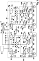
- Fig. 1 shows a circuit diagram of a first embodiment of the braking system.
- the brake system comprises a master brake cylinder 10 and an additional brake fluid reservoir 12.
- At the master brake cylinder 10 is at least partially adjustable in this adjustable (not shown) master cylinder floating piston.
- Under the brake fluid reservoir 12 is not the master cylinder 10 to understand.
- the braking medium reservoir 12 can be understood as meaning a brake fluid volume or a brake fluid reservoir whose internal pressure is adjustable independently of an internal pressure of the master brake cylinder 10 or corresponds to a predetermined pressure, such as the atmospheric pressure.
- the brake fluid reservoir 12 can thus also be designated as a brake fluid storage device, into which a predetermined storage volume of the brake medium of the master brake cylinder 10 can be transferred without back pressure.
- a brake medium exchange bore such as a sniffer bore, may be formed between the master cylinder 10 and the brake fluid reservoir 12, a brake medium exchange bore, such as a sniffer bore, may be formed.
- master cylinder 10 and the brake fluid reservoir 12 may be formed without a hydraulic connection.
- a brake actuator 14 such as a brake pedal
- a brake actuator 14 may be arranged on the master cylinder 10.
- a brake booster 16 is arranged on the master cylinder 10 so that a pressure increase in the inner volume of the master cylinder 10 by means of the brake booster 16 is effected.
- the brake booster 16 may be, for example, a pneumatic, hydraulic brake booster and / or an electromechanical brake booster. It should be noted, however, that the feasibility of the brake booster 16 is not limited to the examples listed here.
- a sensor 17 may also be arranged on the brake actuating element 14 in such a manner that actuation of the brake actuating element 14 by the driver by means of the sensor 17 can be detected.
- the sensor 17 is preferably designed to provide a brake force and / or brake travel signal corresponding to the actuation of the brake actuation element 14 to an evaluation electronics / control electronics (not shown).
- a use for the information provided by the sensor 17 information will be discussed in more detail below.
- the sensor 17 may be a subunit of the brake booster 16.
- the sensor 17 may be a pedal travel sensor, a booster membrane path sensor and / or a rod path sensor. The feasibility of the sensor 17 is not limited to the examples listed here.
- the brake system has an electrically controllable first valve 18, via which a storage chamber 20 is hydraulically connected to the master cylinder 10.
- the hydraulic connection between the storage chamber 20 and the master cylinder 10 is designed such that when adjusting the master cylinder floating piston partially into the master cylinder 10 by a displacement under a predetermined Grenzverstellweg a brake fluid volume back pressure free from the master cylinder 10 on the (at least partially) opened first valve 18 is transferable into the storage chamber 20.
- This can be guaranteed because the Storage chamber 20 is formed as a brake fluid storage device, in which a predetermined storage volume of the brake fluid is transferable back pressure.
- the predetermined Grenzverstellweg corresponds to the predetermined storage volume.
- the storage chamber 20 may be, for example, a low-pressure storage chamber.
- an isolation valve / switching valve can be used, which can be electrically controlled only in an open mode and in a closed mode.
- a bypass line 22 is preferably formed with a check valve 24, which prevents a brake medium displacement via the bypass line 22 from the master cylinder 10 into the storage chamber 20.
- the brake system is controllable by (at least partially) opening the first valve 18 into a mode in which an increase in pressure in the master cylinder 10 is prevented when the master cylinder floating piston is moved in by the adjustment path below the limit displacement path.
- This formed in the first mode "free travel” does not require to be overcome / closed gap between a first contact part of the brake operating member 14 and a second contact part of the master cylinder floating piston.
- the brake system is controllable by closing the first valve 18 in a second mode in which a pressure increase in the master cylinder 10 by means of the in-line of the master cylinder floating piston to the Adjustment under the Grenzverstellweg is effected.
- the driver After controlling the brake system in the second mode by closing the first valve 18, the driver thus has the option of causing an increase in pressure in the master cylinder 10 via an actuation of the brake actuator 14 by an actuation path under the (disable / disable) "free travel".
- the closing of the first valve 18 is faster than the conventional manner for a pressure build-up in a master cylinder to be performed overcoming / closing the "empty way".
- this electrically executable control of the brake system in the second mode is executable without a force to be applied by the driver. Therefore, as will be described in more detail below, in the brake system, the disadvantages of a conventional brake system having a mechanically-formed free travel through a gap between a first contact portion of the brake operating member 14 and a second contact portion of the master cylinder floating piston are eliminated.
- the first valve 18 and the storage chamber 20 thus serve to realize a variable and / or disconnectable idle travel. If the first valve 18 is (at least partially) opened, then the brake medium volume can be shifted from the master cylinder 10 into the storage chamber 20, without first generating a pressure build-up in the master cylinder 10 and a braking effect triggered thereby. If, however, the first valve 18 is closed, an actuation of the brake actuating element 14 with simultaneous co-actuation of the master brake cylinder floating piston directly and preferably without a mechanical free travel causes a buildup of pressure in the master cylinder 10, which can trigger a braking action.
- the first valve 18 is designed as a normally closed valve.
- the brake system is automatically controlled in a malfunction / failure of its electronics or its power supply in the second mode, in which already causes an actuation of the brake actuator 14 to an actuating travel under the "Leerweg” an increase in pressure in the master cylinder 10. The driver can thus brake the vehicle quickly and / or with little effort in such a situation.
- the brake system includes two brake circuits 26 and 28, which are hydraulically connected to the master cylinder 10.
- the first brake circuit 26 is hydraulically connected to the master cylinder 10 via a second valve 30 such that via the (at least partially) opened second valve 30 a pressure increase in the Master cylinder 10 in at least one wheel brake cylinder 32 a and 32 b of the first brake circuit 26 can be forwarded.
- a pressure increase in the at least one wheel brake cylinder 32a and / or 32b of the first brake circuit 26 is inhibited despite a pressure increase in the master cylinder 10.
- a passage from the master cylinder into the at least one wheel brake cylinder 32 a or 32 b of the first brake circuit 26 is therefore prevented in a closed second valve 30.
- the second valve 30 may be designed as an electrically controllable switching valve / separating valve, which is switchable only in a closed state and in an open state.
- the second valve may also be a steadily adjustable / continuously controllable valve.
- the second valve 30 is designed as a normally open valve.
- the brake system comprises a control device 34, which in its function is only partially shown schematically, by means of which the first valve 18 and the second valve 30 can be switched in antiphase.
- a control device 34 By energizing the valves 18 and 30 with a control signal 36, the normally closed closed first valve 18 is closed when opening the normally open second valve 30 is formed and opened according to a closing of the second valve 30.
- the control device 34 thus a cost electronics can be used.
- the first brake circuit 26 is designed such that a brake pressure in the at least one wheel brake cylinder 32a and / or 32b of the first brake circuit 26 is independent of a pressure present in the second brake circuit 28 and the master brake cylinder 10 after closing the second valve 30 buildable / adjustable.
- a suitable configuration of the first brake circuit 26 for an actively adjustable brake pressure in two wheel brake cylinders 32a and 32b after closing the second valve 30 will be described.
- the one described here Brake system is not limited to such a configuration of the first brake circuit 26.
- the first brake circuit 26 has a first pump 38, by means of which a volume from the brake fluid reservoir 12 in at least one wheel brake cylinder 32 a and 32 b is pumpable. Likewise, by means of the first pump 38, a volume from the first brake circuit 26 can be conveyed back into the brake medium reservoir 12.
- the first brake circuit 26 is connected via a suction line 40 to the brake fluid reservoir 12.
- the first brake circuit 26 may include at least one continuously variable valve via which the wheel brake cylinders 32a and 32b are hydraulically connected to the brake fluid reservoir 12.
- the Radauslassventile 42a and 42b associated with the wheel brake cylinders 32a and 32b are designed as continuously adjustable valves.
- the active reduction of the brake pressure in the wheel brake cylinders 32a and 32b by the Bremsmediumverschiebung in the brake fluid reservoir 12 without an additional continuously variable valve of the first brake circuit 26 is executable.
- the brake medium displacement from the first brake circuit 26 into the brake medium reservoir 40 can also be carried out without the wheel outlet valves 42a and 42b being designed as the at least one continuously variable valve.
- the first brake circuit 26 is arranged on a first supply line 44, via which the first valve 18, a line 46 leading from the first valve 18 to the storage chamber 20 and the storage chamber 20 are connected to the master cylinder 10.
- the second valve 30 is hydraulically connected to the master cylinder 10 via a branch point 48 in the first supply line 44 and a line 50 leading therefrom.
- a line 52 leads to a first Radeinlassventil 54 a, which is associated with a first wheel brake cylinder 32 a of the first brake circuit 26.
- a wheel inlet valve 54b assigned to the second wheel brake cylinder 32b of the first brake circuit 26 is also connected to the second valve 30.
- Each of the two Radeinlassventile 54a and 54b is connected via a line 60a or 60b with the associated Wheel brake cylinder 32 a and 32 b connected.
- Parallel to each of the two Radeinlassventile 64a and 64b each have a bypass line 62a and 62b disposed therein a check valve 64a and 64b.
- the check valves 64a and 64b are aligned such that brake fluid displacement through the associated bypass line 62a or 62b from the second valve 30 to the associated wheel brake cylinder 32a or 32b is inhibited.
- a branching point 66a and 66b is formed, to which each one of the above-described Radauslassventile 42a or 42b are connected via a line 68a or 68b.
- a line 70a and 70b leads to a common branch point 72.
- the branch point 72 is connected via a line 74 to the suction side of the first pump 38.
- the suction line 40 already described above runs.
- a pressure relief valve 76 is used, whose function will be described in more detail below.
- the delivery side of the first pump 38 is connected via a line 80 to a branch point 82 formed in the line 52. With the line 52 and a first pressure sensor 84 of the first brake circuit 26 is connected.
- the brake system additionally has the second brake circuit 28 in addition to the first brake circuit 26.
- the second brake circuit 28 is formed so that the brake pressure in the at least one wheel brake cylinder 86a and 86b of the second brake circuit 28 increases (automatically) with an increase in the internal pressure in the master cylinder 10. This can also be described in such a way that the driver, after overcoming the means of (at least partial) opening of the first valve 18 adjustable idle travel and / or after switching off / deactivating the idle travel by closing the first valve 18 has the opportunity directly in to brake the at least one wheel brake cylinder 86 of the second brake circuit 28.
- the second brake circuit 28 may correspond to a conventional ESP system.
- the second brake circuit 28 is hydraulically connected to the master cylinder 10 via a second supply line 88, which leads to a main switching valve 90 of the second brake circuit 28. About one formed in the second supply line 88 Branch point 92 and one of them continuing line 94 and a switching valve 96 of the second brake circuit 28 is connected to the master cylinder 10. Parallel to the switching valve 96 extends a bypass line 98 in which a check valve 100 is arranged. The check valve 100 is aligned so that a braking medium displacement is prevented by the bypass line 98 from a wheel brake cylinder side arranged on the switching valve 96 line 102 to the line 94. Via a branch point 104 in the second supply line 88, a second pressure sensor 106 is arranged on the second brake circuit 28.
- the line 102 connects the switching valve 96 with a first Radeinlassventil 108 a, which is associated with the first wheel brake cylinder 86 a of the second brake circuit 28.
- a wheel inlet valve 108b assigned to the second wheel brake cylinder 86b of the second brake circuit 28 is also connected to the changeover valve 96.
- Each of the two wheel inlet valves 108a and 108b is connected via a respective line 114a or 114b to the associated wheel brake cylinder 86a or 86b of the second brake circuit 28.
- Parallel to the two Radeinlassventilen 108a and 108b extends each a bypass line 116a and 116b, each with a check valve 118a and 118b.
- Each of the check valves 118a and 118b is aligned to inhibit brake fluid displacement through the associated bypass line 116a or 116b from the line 102 to the associated wheel brake cylinder 86a or 86b.
- Each of the two wheel brake cylinders 86a and 86b of the second brake circuit 28 is also associated with a wheel outlet valve 120a and 120b, which is connected via a respective line 122a or 122b to a branch point 124a formed in the line 114a or to a branch point 124b formed in the line 114b.
- the two Radauslassventile 120a and 120b are also connected via a respective line 126a and 126b with a common branch point 128.
- a line 130 extends to a suction side of a second pump 132.
- the main switching valve 90 is also connected to the delivery side of the second pump 132.
- a further storage chamber 138 is connected to the delivery side of the second pump 132 via a branch point 140 formed in the conduit 130.
- An overpressure valve 142 in the conduit 130 is oriented so that brake fluid displacement from the wheel outlet valves 120a and 120b to the suction side of the second pump 132 is possible only at a certain pressure.
- the delivery side of the second pump 132 is connected via a line 144 to a branching point 146 formed in the line 102.
- the first pump 38 and the second pump 132 are preferably arranged on a common shaft 148 of a motor 150.
- the pressure relief valve arranged in the suction line 40 ensures, when the first pump 38 is co-operated with the second pump 132, a back transfer of the brake medium volume pumped from the first pump 38 from the brake medium reservoir 12 into the brake medium reservoir 12 so that no excess pressure builds up in the first brake circuit 26 becomes.
- the two Radeinlassventile 54a and 54b are closed when the first pump 38 is running when the braking pressure in the second brake circuit by means of the second pump 132 is to be increased if the brake pressure in the first brake circuit 26.
- the first pump 38 and / or the second pump 132 may be a three-piston pump.
- the brake system described here is thus executable as a six-piston ESP system.
- a pump with a different number of pistons an asymmetrical pump and / or a gear pump can be used as the first pump 38 and / or as the second pump 132.
- This in Fig. 1 illustrated brake system has exactly twelve electrically controllable valves 18, 30, 42a, 42b, 54a, 54b, 90, 96, 108a, 108b, 120a and 120b, which by means of the control device 34 at least in an open and in a closed state are controllable. Due to the number of controllable valves, the control device 34 is inexpensive to carry out.
- the Radeinlassventile 54a, 54b, 108a and 108b and the switching valve 96 are designed as normally open valves.
- the Radauslassventile 42 a, 41 b, 120 a and 120 b and the main switching valve 90 a normally closed training is preferred.
- the two wheel brake cylinders 32a and 32b of the first brake circuit 26 may be associated with the wheels of a first vehicle axle, while the two wheel brake cylinders 86a and 86b of the second brake circuit 28 are disposed on the wheels of a second vehicle axle.
- the wheel brake cylinders 32a and 32b of the first brake circuit 26 are preferably associated with the rear axle. In this case, it is advantageous if a (not outlined) generator is arranged on the rear axle.
- the brake system described here is not limited to an axle brake circuit distribution. Instead, the brake system may also be used for a vehicle having an X-brake circuit split.
- the first valve 18 can be opened upon detection of the driver's braking request and the second valve 30 can be closed.
- the second valve 30 can be closed.
- at least the above-mentioned predetermined storage volume of the brake fluid can be moved counter pressure into the storage chamber 20.
- a pressure build-up in the master cylinder 10 is thus prevented.
- the generator may be used to charge the battery without exceeding the maximum vehicle deceleration given by the driver. This is identical to a conventional Leerweg realized by forming a gap between the brake actuator 14 and the master cylinder floating piston identical functionality.
- An advantageous control of Radauslassventile 42a and 42b of the first brake circuit 26 for actively adjusting the brake pressure in the associated Radbremszylindern 32a and 32b can be executed by a complete closing of one of the two Radauslassventile 42a or 42b, the control of the total brake pressure of the two wheel brake cylinders 32a and 32b via the other (non-closed) Radauslassventil 42a or 42b takes place.
- at least one of the two wheel outlet valves 42a and 42b of the first brake circuit 26 can be opened and the total brake pressure in the associated wheel brake cylinders 32a and 32b can be set in accordance with the decreasing braking request.
- the braking medium volume emerging from the at least one wheel brake cylinder 32a and 32b can be conveyed via at least one of the wheel outlet valves 42a or 42b are transferred back into the brake fluid reservoir 12.
- Other control strategies for actively setting the brake pressures in the two wheel brake cylinders 32a and 32b of the first brake circuit 26 are also feasible.
- pressure regulation using the first pressure sensor 84 or at least one pressure sensor may be performed on a wheel associated with the wheel brake cylinders 32a or 32b.
- the pressure build-up in the second brake circuit 28 can be conventional and independent of the total brake pressure of the two wheel brake cylinders 32a and 32b of the first brake circuit 26, or be modulated by the driver.
- active pressure assemblies without actuation of the brake actuator 14 by the driver in a conventional manner by opening the main switching valve 90 in the second brake circuit 28 executable.
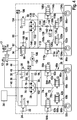
- Fig. 2 shows a circuit diagram of a second embodiment of the braking system.
- Fig. 2 shown brake system differs from the embodiment described above in that it is dispensed with an equipment of the brake system with a storage chamber as a brake medium storage device. Instead, the first valve 18 is connected via line 46 and the branch point 152 in the line 74 to the brake fluid reservoir 12.
- the first valve 18 thus opens or closes a hydraulic connection between the master brake cylinder 10 and the brake fluid reservoir 12.
- Fig. 3 and Fig. 4 each show a circuit diagram of a third and fourth embodiment of the brake system.
- Fig. 3 and Fig. 4 illustrated embodiments have no brake booster compared to the brake systems described above.
- the brake systems described here are preferably used on a vehicle such that the wheels arranged on the front axle of the vehicle can be braked by means of the wheel brake cylinders 32a and 32b of the first brake circuit 26. Especially with such an installation of the brake systems, the advantages listed above are guaranteed.
- the driver thus has the opportunity to brace unreinforced in the rear axle and in this way to obtain a favorable brake feel (pedal feel).
- the pressure build-up on the front axle can take place actively, whereby preferably a gain of the driver's braking request which relieves the driver by force is automatically carried out.
- these brake systems have the advantages of an adjustable braking force distribution even with a lack of vacuum availability.
- All brake systems described above ensure over a standard brake system additionally has the advantage that due to the rapid detection of a driver's braking request by means of the sensor 17 is early reactable to the driver's brake request.
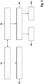
- FIG. 12 is a flow chart showing one embodiment of a method of operating a brake system of a vehicle not covered by the present invention.
- This in Fig. 5 illustrated method is executable with a brake system with a master cylinder with an at least partially hineinver dichloric pump and a brake fluid storage device, in which a predetermined storage volume of a brake medium is push-back hineintransferierbar. It should be noted that the feasibility of the method is not limited to the brake systems described above.
- an internal pressure in the master brake cylinder is partially increased in an adjustment of the master cylinder floating piston in the master cylinder by an adjustment under a storage volume corresponding Grenzverstellweg. This is done by closing an electrically controllable first valve, via which the brake fluid storage device is hydraulically connected to the master cylinder.
- a method step S2 is carried out, in which a second valve, via which a brake circuit of the brake system with at least one wheel brake cylinder is hydraulically connected to the master cylinder, is controlled in an at least partially open mode.
- a method step S3 may also be carried out in which an increase in the internal pressure in the master cylinder during the adjustment of the master cylinder floating piston by the adjustment under the Grenzverstellweg is prevented by at least partially open the first valve. This ensures that a brake medium volume smaller than the predetermined storage volume is transferred back pressure-free from the master brake cylinder via the at least partially opened first valve in the brake medium storage device.
- the second valve is controlled in a closed mode (method step S4).
- a brake medium volume can be pumped from a brake medium reservoir into the at least one wheel brake cylinder of the brake circuit (method step S41).
- a brake medium volume can be pumped from a brake medium reservoir into the at least one wheel brake cylinder of the brake circuit (method step S41).
- a method step S42 at least one continuously adjustable valve of the brake circuit, via which the at least one wheel brake cylinder can be hydraulically connected to the Brake medium reservoir is connected to be opened. In this way, a brake medium displacement from the at least one wheel brake cylinder in the brake fluid reservoir executable.
- the brake pressure in the at least one wheel brake cylinder of the brake circuit is actively adjustable.
- step S42 only one of a first wheel outlet valve and a second wheel outlet valve of the brake circuit is at least partially opened as a continuously variable valve for carrying out the brake medium displacement from a first wheel brake cylinder or from a second wheel brake cylinder of the brake circuit into the brake medium reservoir. If, for example, one of the two wheel inlet valves of the brake circuit has to be closed due to an ABS control on the assigned wheel, then the pressure adjustment can take place via the wheel outlet valve assigned to the other wheel of the common axle.
- the functionality of the controllable pressure adjustment can thus be carried out optionally with a Radauslassventil the two Radauslassventile a common axis. Even a possibly necessary complete braking is feasible in this way.
- the method described here can be combined with the conventional ABS control.
Landscapes
- Engineering & Computer Science (AREA)
- Transportation (AREA)
- Mechanical Engineering (AREA)
- Physics & Mathematics (AREA)
- Fluid Mechanics (AREA)
- Electromagnetism (AREA)
- Regulating Braking Force (AREA)
Claims (3)
- Système de freinage pour un véhicule, avec
un maître-cylindre (10) avec un piston flottant de maître-cylindre déplaçable au moins partiellement vers l'intérieur du maître-cylindre (10);
un dispositif d'accumulation de liquide de frein (12, 20), dans lequel un volume d'accumulation prédéterminé d'un liquide de frein peut être transféré, dans lequel le dispositif d'accumulation de liquide de frein (12, 20) est un réservoir de liquide de frein (12) ou une chambre d'accumulation à basse pression (20);
une première vanne fermée sans courant (18), qui est hydrauliquement raccordée au maître-cylindre (10) par une première conduite d'alimentation (44) et par laquelle le dispositif d'accumulation de liquide de frein (12, 20) est hydrauliquement raccordé au maître-cylindre (10), de telle manière que, lors d'un déplacement du piston flottant de maître-cylindre en partie dans le maître-cylindre (10) d'une course inférieure à une course limite correspondant au volume d'accumulation, un volume de liquide de frein inférieur au volume d'accumulation prédéterminé puisse être transféré du maître-cylindre (10) au dispositif d'accumulation de liquide de frein (12, 20) par ladite première vanne au moins partiellement ouverte (18);
un premier circuit de freinage (26) avec deux cylindres de frein de roue (32a, 32b) et chaque fois une vanne d'entrée de roue (54a, 54b) et chaque fois une vanne de sortie de roue (42a, 42b) par cylindre de frein de roue (32a, 32b), dans lequel chacune des deux vannes d'entrée de roue (54a, 54b) et des deux vannes de sortie de roue (42a, 42b) du premier circuit de freinage (26) présente deux raccords et est chaque fois une vanne réglable en continu;
une deuxième vanne ouverte sans courant (30), qui est hydrauliquement raccordée au maître-cylindre (10) par un point de branchement (48) dans la première conduite d'alimentation (44) et par laquelle le premier circuit de freinage (26) est hydrauliquement raccordé au maître-cylindre (10), de telle manière qu'une augmentation de pression dans les deux cylindres de frein de roue (32a, 32b) du premier circuit de freinage (26) lors de l'augmentation de pression dans le maître-cylindre (10) puisse être empêchée par la deuxième vanne fermée (30), et qu'une augmentation de pression dans les deux cylindres de frein de roue (32a, 32b) du premier circuit de freinage (26) lors de l'augmentation de pression dans le maître-cylindre (10) puisse être transférée par la deuxième vanne au moins partiellement ouverte (30);
un deuxième circuit de freinage (28) avec deux cylindres de frein de roue (86a, 86b), une vanne d'inversion (96), une vanne de commande haute pression (90), et chaque fois une vanne d'entrée de roue (108a, 108b) et chaque fois une vanne de sortie de roue (120a, 120b) par cylindre de frein de roue (86a, 86b), dans lequel chacune des deux vannes d'entrée de roue (54a, 54b) du deuxième circuit de freinage (28) présente deux raccords et est chaque fois une vanne réglable en continu et chacune des deux vannes de sortie de roue (42a, 42b) du deuxième circuit de freinage (28) présente deux raccords et est chaque fois une vanne de commande, dans lequel le deuxième circuit de freinage (28) est hydrauliquement raccordé au maître-cylindre (10) par une deuxième conduite d'alimentation (88) conduisant à la vanne de commande haute pression (90), et dans lequel la vanne d'inversion (96) est également raccordée hydrauliquement au maître-cylindre (10) par un point de branchement (92) formé dans la deuxième conduite d'alimentation (88); et
un dispositif de commande (34), au moyen duquel chacune des deux vannes d'entrée de roue (54a, 54b) et des deux vannes de sortie de roue (42a, 42b) du premier circuit de freinage (26), chacune des deux vannes d'entrée de roue (54a, 54b) et des deux vannes de sortie de roue (42a, 42b) du deuxième circuit de freinage (28), la vanne d'inversion (96) et la vanne de commande haute pression (90) peuvent être commandées et en outre la première vanne (18) et la deuxième vanne (30) peuvent être commutées en opposition de phase, de telle manière que, par une commande de la première vanne (18) dans son état ouvert et de la deuxième vanne (30) dans son état fermé, le système de freinage puisse être commandé dans un premier mode, dans lequel une augmentation de pression dans le maître-cylindre (10) lors du déplacement du piston flottant de maître-cylindre en partie dans le maître-cylindre (10) de la course inférieure à la course limite est empêchée, et que, par une commande de la première vanne (18) dans son état fermé et de la deuxième vanne (30) dans son état ouvert, le système de freinage puisse être commandé dans un deuxième mode, dans lequel une augmentation de pression dans le maître-cylindre (10) au moyen du déplacement du piston flottant de maître-cylindre en partie dans le maître-cylindre (10) de la course inférieure à la course limite est garantie, caractérisé en ce que
par la commande de la première vanne (18) dans son état ouvert et de la deuxième vanne (30) dans son état fermé, une interaction du maître-cylindre (10) dans les deux cylindres de frein de roue (32a, 32b) du premier circuit de freinage (26) et une augmentation de pression dans les deux cylindres de frein de roue (32a, 32b) du premier circuit de freinage (26) sont empêchées malgré une augmentation de pression dans le maître-cylindre à cause de la deuxième vanne fermée (30);
par la commande de la première vanne (18) dans son état fermé et de la deuxième vanne (30) dans son état ouvert, une augmentation de pression dans le maître-cylindre (10) peut être retransmise dans les deux cylindres de frein de roue (32a, 32b) du premier circuit de freinage (26) par la deuxième vanne (30) au moins partiellement ouverte; et
le système de freinage présente exactement douze vannes pouvant être commandées (18, 30, 42a, 42b, 54a, 54b, 90, 96, 108a, 108b, 120a, 120b) comme la première vanne (18), la deuxième vanne (30), les deux vannes d'entrée de roue (54a, 54b) et les deux vannes de sortie de roue (42a, 42b) du premier circuit de freinage (26), les deux vannes d'entrée de roue (54a, 54b) et les deux vannes de sortie de roue (42a, 42b) du deuxième circuit de freinage (28), la vanne d'inversion (96) et la vanne de commande haute pression (90), qui peuvent être commandées au moins dans leur état ouvert et dans leur état fermé au moyen d'au moins un signal de commande électrique (36) généré par le dispositif de commande (34), dans lequel la première vanne (18) et la deuxième vanne (30) peuvent être commandées en opposition de phase respectivement dans son état ouvert et dans son état fermé par un signal de courant commun du dispositif de commande (34) en tant que signal de commande (36). - Système de freinage selon la revendication 1, dans lequel le premier circuit de freinage (26) comprend une pompe (38), au moyen de laquelle un autre volume de liquide de frein peut être pompé dans les deux cylindres de frein de roue (32a, 32b) du premier circuit de freinage (26) à partir du réservoir de liquide de frein utilisé comme dispositif d'accumulation de liquide de frein (12, 20) ou d'un réservoir de liquide de frein supplémentaire (12).
- Système de freinage selon la revendication 2, dans lequel le système de freinage comprend une soupape de sûreté (76) disposée entre un côté de pression de la pompe (38) et le réservoir de liquide de frein (12).
Applications Claiming Priority (2)
| Application Number | Priority Date | Filing Date | Title |
|---|---|---|---|
| DE102010042990A DE102010042990A1 (de) | 2010-10-27 | 2010-10-27 | Bremssystem für ein Fahrzeug und Verfahren zum Betreiben eines Bremssystems eines Fahrzeugs |
| PCT/EP2011/065119 WO2012055617A1 (fr) | 2010-10-27 | 2011-09-01 | Système de freinage pour un véhicule, et procédé de fonctionnement d'un système de freinage de véhicule |
Publications (2)
| Publication Number | Publication Date |
|---|---|
| EP2632781A1 EP2632781A1 (fr) | 2013-09-04 |
| EP2632781B1 true EP2632781B1 (fr) | 2017-03-01 |
Family
ID=44545734
Family Applications (1)
| Application Number | Title | Priority Date | Filing Date |
|---|---|---|---|
| EP11751898.5A Active EP2632781B1 (fr) | 2010-10-27 | 2011-09-01 | Système de freinage pour un véhicule |
Country Status (7)
| Country | Link |
|---|---|
| US (1) | US9403518B2 (fr) |
| EP (1) | EP2632781B1 (fr) |
| KR (1) | KR101956394B1 (fr) |
| CN (1) | CN103167978B (fr) |
| DE (1) | DE102010042990A1 (fr) |
| ES (1) | ES2626430T3 (fr) |
| WO (1) | WO2012055617A1 (fr) |
Families Citing this family (17)
| Publication number | Priority date | Publication date | Assignee | Title |
|---|---|---|---|---|
| DE102013206324A1 (de) * | 2013-04-10 | 2014-10-16 | Robert Bosch Gmbh | Bremssystem für ein Fahrzeug und Verfahren zum Betreiben des Bremssystems |
| DE102013017205A1 (de) * | 2013-10-16 | 2015-04-16 | Audi Ag | Kraftfahrzeug mit einem brake-by-wire-Bremssystem |
| DE102014205605B4 (de) * | 2014-03-26 | 2020-10-29 | Ford Global Technologies, Llc | Verfahren zur Bremsrekuperation in einem Kraftfahrzeug und Kraftfahrzeug geeignet zur Durchführung des Verfahrens |
| DE102014006584A1 (de) * | 2014-05-03 | 2015-11-05 | Audi Ag | Verfahren zum Erkennen eines Fehlverbaus von Bremsleitungen |
| DE102014212538A1 (de) * | 2014-06-30 | 2015-12-31 | Continental Teves Ag & Co. Ohg | Anordnung für eine hydraulische Kraftfahrzeug-Bremsanlage sowie Bremsanlage mit einer solchen Anordnung |
| DE102016208529A1 (de) * | 2016-05-18 | 2017-11-23 | Robert Bosch Gmbh | Bremssystem für ein Fahrzeug und Verfahren zum Betreiben eines Bremssystems eines Fahrzeugs |
| DE102016216542A1 (de) * | 2016-09-01 | 2018-03-01 | Continental Teves Ag & Co. Ohg | Verfahren zum Betreiben eines Fahrzeugbremssystems |
| DE102016218337A1 (de) * | 2016-09-23 | 2018-03-29 | Continental Teves Ag & Co. Ohg | Verfahren zum Betreiben eines Bremssystems |
| DE102017213392A1 (de) * | 2017-08-02 | 2019-02-07 | Robert Bosch Gmbh | Steuervorrichtung und Verfahren zum Betreiben eines Simulator-bestückten hydraulischen Bremssystems eines Fahrzeugs |
| DE102018202885A1 (de) * | 2018-02-26 | 2019-08-29 | Robert Bosch Gmbh | Mehrkreisiges hydraulisch offenes Bremssystem, insbesondere für ein hochautomatisiertes oder autonomes Fahrzeug |
| DE102018206566A1 (de) * | 2018-04-27 | 2019-10-31 | Robert Bosch Gmbh | Fahrzeugbremssystem und Verfahren zur Bremsdrucksteigerung in einem ersten Radbremszylinder und Bremsdruckbegrenzung in einem zweiten Radbremszylinder eines Fahrzeugbremssystems |
| DE102018207207A1 (de) * | 2018-05-09 | 2019-11-14 | Robert Bosch Gmbh | Verfahren zum Steuern einer Fahrdynamikregelungsvorrichtung und Fahrdynamikregelungsvorrichtung |
| DE102018212293A1 (de) * | 2018-07-24 | 2020-01-30 | Robert Bosch Gmbh | Steuervorrichtung und Verfahren zum Betreiben eines Magnetventils |
| DE102018214548A1 (de) * | 2018-08-28 | 2020-03-05 | Robert Bosch Gmbh | Steuervorrichtung und Verfahren zum Bestimmen einer Ist-Größe bezüglich eines Durchflussfaktors mindestens eines Radauslassventils eines zweikreisigen Bremssystems eines Fahrzeugs |
| DE102018222164A1 (de) * | 2018-12-18 | 2020-06-18 | Robert Bosch Gmbh | Verfahren zur Steuerung eines hydraulischen Bremssystems sowie entsprechende Vorrichtung |
| DE202019101596U1 (de) * | 2019-02-12 | 2020-05-13 | Ipgate Ag | Hydrauliksystem mit mindestens zwei hydraulischen Kreisen und mindestens zwei Druckversorgungseinrichtungen |
| CN113815424B (zh) * | 2020-06-19 | 2023-09-22 | 广州汽车集团股份有限公司 | 车辆制动力控制方法、装置和计算机可读存储介质 |
Citations (2)
| Publication number | Priority date | Publication date | Assignee | Title |
|---|---|---|---|---|
| US3749125A (en) * | 1971-02-26 | 1973-07-31 | Fiat Spa | Solenoid-actuated pneumatic actuator for anti-skid vehicle braking systems |
| DE19963760A1 (de) * | 1999-12-30 | 2001-07-05 | Bosch Gmbh Robert | Hydraulische Fahrzeugbremsanlage |
Family Cites Families (19)
| Publication number | Priority date | Publication date | Assignee | Title |
|---|---|---|---|---|
| DE3912234A1 (de) | 1989-04-14 | 1990-10-18 | Teves Gmbh Alfred | Hydraulische bremsanlage |
| DE4322182B4 (de) | 1993-07-03 | 2005-02-03 | Robert Bosch Gmbh | Hydraulische Fremdkraftbremsanlage mit Notbremszylinder |
| DE19604134B4 (de) | 1996-02-06 | 2004-11-11 | Robert Bosch Gmbh | Verfahren und Vorrichtung zur Steuerung der Bremsanlage von Kraftfahrzeugen mit elektrischem Antrieb |
| DE19701070A1 (de) | 1997-01-15 | 1998-07-16 | Bosch Gmbh Robert | Hydraulische Fahrzeugbremsanlage |
| JPH11285102A (ja) | 1998-03-27 | 1999-10-15 | Nabco Ltd | 電気自動車用制動装置 |
| JP3496549B2 (ja) * | 1998-04-17 | 2004-02-16 | トヨタ自動車株式会社 | 液圧ブレーキ装置 |
| JP2002255018A (ja) | 2001-02-28 | 2002-09-11 | Bosch Braking Systems Co Ltd | ブレーキシステム |
| WO2003053755A1 (fr) | 2001-12-20 | 2003-07-03 | Continental Teves Ag & Co. Ohg | Systeme de freinage electro-hydraulique pour automobiles |
| JP2004203189A (ja) * | 2002-12-25 | 2004-07-22 | Advics:Kk | 液圧ブレーキ装置 |
| DE102004045391A1 (de) | 2004-09-18 | 2006-03-23 | Robert Bosch Gmbh | Verfahren zur Steuerung oder Regelung eines elektronisch ansteuerbaren, nach dem Rückförderprinzip arbeitenden Fahrzeugbremssystems und elektronisch ansteuerbares, nach dem Rückförderprinzip arbeitendes Fahrzeugbremssystem |
| DE102005041983A1 (de) * | 2005-09-05 | 2007-03-08 | Robert Bosch Gmbh | Hydraulische Bremsanlage mit zusätzlichem Hydraulikspeicher sowie Verfahren zum Betreiben einer Bremsanlage |
| JP4839791B2 (ja) | 2005-11-18 | 2011-12-21 | 株式会社アドヴィックス | 車両用ブレーキ制御装置 |
| DE102007028070A1 (de) | 2007-06-19 | 2008-12-24 | Lucas Automotive Gmbh | Bremsausrüstung für ein Landfahrzeug |
| JP2009040162A (ja) | 2007-08-07 | 2009-02-26 | Toyota Motor Corp | ブレーキ制御装置及びブレーキ制御方法 |
| DE102008004201A1 (de) * | 2008-01-14 | 2009-07-16 | Robert Bosch Gmbh | Bremssystem und Verfahren zum Steuern eines Bremssystems |
| KR20090090452A (ko) | 2008-02-21 | 2009-08-26 | 주식회사 만도 | 시뮬레이션 기능을 가진 전자제어식 브레이크 시스템 |
| DE102008002345A1 (de) | 2008-06-11 | 2009-12-17 | Robert Bosch Gmbh | Bremseinrichtung für ein Kraftfahrzeug mit wenigstens drei Bremskreisen |
| DE102009001401A1 (de) | 2009-03-09 | 2010-09-16 | Robert Bosch Gmbh | Bremssystem, Verfahren zum Betreiben eines Bremssystems und Herstellungsverfahren für ein Bremssystem |
| JP5454893B2 (ja) * | 2009-09-28 | 2014-03-26 | 株式会社アドヴィックス | 制動制御装置と当該制動制御装置に用いられるモータ回転数演算方法 |
-
2010
- 2010-10-27 DE DE102010042990A patent/DE102010042990A1/de not_active Withdrawn
-
2011
- 2011-09-01 US US13/881,699 patent/US9403518B2/en active Active
- 2011-09-01 CN CN201180052306.6A patent/CN103167978B/zh active Active
- 2011-09-01 ES ES11751898.5T patent/ES2626430T3/es active Active
- 2011-09-01 WO PCT/EP2011/065119 patent/WO2012055617A1/fr not_active Ceased
- 2011-09-01 KR KR1020137013428A patent/KR101956394B1/ko active Active
- 2011-09-01 EP EP11751898.5A patent/EP2632781B1/fr active Active
Patent Citations (2)
| Publication number | Priority date | Publication date | Assignee | Title |
|---|---|---|---|---|
| US3749125A (en) * | 1971-02-26 | 1973-07-31 | Fiat Spa | Solenoid-actuated pneumatic actuator for anti-skid vehicle braking systems |
| DE19963760A1 (de) * | 1999-12-30 | 2001-07-05 | Bosch Gmbh Robert | Hydraulische Fahrzeugbremsanlage |
Also Published As
| Publication number | Publication date |
|---|---|
| US20130292999A1 (en) | 2013-11-07 |
| KR101956394B1 (ko) | 2019-03-11 |
| EP2632781A1 (fr) | 2013-09-04 |
| KR20130133782A (ko) | 2013-12-09 |
| CN103167978A (zh) | 2013-06-19 |
| ES2626430T3 (es) | 2017-07-25 |
| US9403518B2 (en) | 2016-08-02 |
| CN103167978B (zh) | 2016-10-12 |
| DE102010042990A1 (de) | 2012-05-03 |
| WO2012055617A1 (fr) | 2012-05-03 |
Similar Documents
| Publication | Publication Date | Title |
|---|---|---|
| EP2632781B1 (fr) | Système de freinage pour un véhicule | |
| DE102010030921B4 (de) | Bremssystem für ein Fahrzeug und Verfahren zum Betreiben eines Bremssystems eines Fahrzeugs | |
| EP2539195B1 (fr) | Système de freinage pour véhicule et procédé pour faire fonctionner un système de freinage d'un véhicule | |
| EP2234853B1 (fr) | Système de freinage | |
| EP2709882B1 (fr) | Dispositif de commande d'un système de freinage d'un véhicule et procédé de fonctionnement d'un système de freinage d'un véhicule | |
| EP2739512B1 (fr) | Dispositif de commande pour une installation de freinage d'un véhicule, installation de freinage d'un véhicule et procédé de fonctionnement de l'installation de freinage d'un véhicule | |
| EP2709884B1 (fr) | Système de freinage régénératif pour véhicule et méthode pour mettre en oeuvre un tel système. | |
| EP2688780B1 (fr) | Système de freinage et véhicule avec un tel système de freinage | |
| EP2991868B1 (fr) | Système de freinage hydraulique pour un véhicule et procédé pour faire fonctionner un système de freinage hydraulique d'un véhicule | |
| EP2931572B1 (fr) | Procédé pour faire fonctionner un système de freinage d'un véhicule et dispositif de commande d'un système de freinage d'un véhicule | |
| DE102008003664A1 (de) | Bremssystem und Verfahren zum Betreiben eines Bremssystems | |
| DE102010038548B4 (de) | Bremssystem für ein Fahrzeug und Verfahren zum Betreiben eines Bremssystems für ein Fahrzeug | |
| EP2539194A1 (fr) | Système de freinage pour véhicule et procédé pour faire fonctionner un système de freinage d'un véhicule | |
| DE102017200752A1 (de) | Verfahren zum Betrieb einer Bremsanlage für Kraftfahrzeuge und Bremsanlage | |
| EP1888386B1 (fr) | Compensation d'une baisse d'efficacite de freinage d'un systeme de freinage hydraulique pour vehicule terrestre | |
| EP2709883B1 (fr) | Dispositif de commande d'un système de freinage d'un véhicule et procédé de fonctionnement d'un système de freinage d'un véhicule | |
| DE102010029851B4 (de) | Bremssystem für ein Fahrzeug und Verfahren zum Betreiben eines Bremssystems eines Fahrzeugs | |
| DE102014213354A1 (de) | Bremssystem für ein Fahrzeug und Verfahren zum Betreiben eines Bremssystems eines Fahrzeugs |
Legal Events
| Date | Code | Title | Description |
|---|---|---|---|
| PUAI | Public reference made under article 153(3) epc to a published international application that has entered the european phase |
Free format text: ORIGINAL CODE: 0009012 |
|
| 17P | Request for examination filed |
Effective date: 20130527 |
|
| AK | Designated contracting states |
Kind code of ref document: A1 Designated state(s): AL AT BE BG CH CY CZ DE DK EE ES FI FR GB GR HR HU IE IS IT LI LT LU LV MC MK MT NL NO PL PT RO RS SE SI SK SM TR |
|
| DAX | Request for extension of the european patent (deleted) | ||
| 17Q | First examination report despatched |
Effective date: 20150424 |
|
| GRAP | Despatch of communication of intention to grant a patent |
Free format text: ORIGINAL CODE: EPIDOSNIGR1 |
|
| INTG | Intention to grant announced |
Effective date: 20161019 |
|
| GRAS | Grant fee paid |
Free format text: ORIGINAL CODE: EPIDOSNIGR3 |
|
| GRAA | (expected) grant |
Free format text: ORIGINAL CODE: 0009210 |
|
| AK | Designated contracting states |
Kind code of ref document: B1 Designated state(s): AL AT BE BG CH CY CZ DE DK EE ES FI FR GB GR HR HU IE IS IT LI LT LU LV MC MK MT NL NO PL PT RO RS SE SI SK SM TR |
|
| REG | Reference to a national code |
Ref country code: GB Ref legal event code: FG4D Free format text: NOT ENGLISH |
|
| REG | Reference to a national code |
Ref country code: CH Ref legal event code: EP Ref country code: AT Ref legal event code: REF Ref document number: 870886 Country of ref document: AT Kind code of ref document: T Effective date: 20170315 |
|
| REG | Reference to a national code |
Ref country code: IE Ref legal event code: FG4D Free format text: LANGUAGE OF EP DOCUMENT: GERMAN |
|
| REG | Reference to a national code |
Ref country code: DE Ref legal event code: R096 Ref document number: 502011011742 Country of ref document: DE |
|
| REG | Reference to a national code |
Ref country code: NL Ref legal event code: MP Effective date: 20170301 |
|
| REG | Reference to a national code |
Ref country code: LT Ref legal event code: MG4D |
|
| REG | Reference to a national code |
Ref country code: ES Ref legal event code: FG2A Ref document number: 2626430 Country of ref document: ES Kind code of ref document: T3 Effective date: 20170725 |
|
| PG25 | Lapsed in a contracting state [announced via postgrant information from national office to epo] |
Ref country code: FI Free format text: LAPSE BECAUSE OF FAILURE TO SUBMIT A TRANSLATION OF THE DESCRIPTION OR TO PAY THE FEE WITHIN THE PRESCRIBED TIME-LIMIT Effective date: 20170301 Ref country code: LT Free format text: LAPSE BECAUSE OF FAILURE TO SUBMIT A TRANSLATION OF THE DESCRIPTION OR TO PAY THE FEE WITHIN THE PRESCRIBED TIME-LIMIT Effective date: 20170301 Ref country code: HR Free format text: LAPSE BECAUSE OF FAILURE TO SUBMIT A TRANSLATION OF THE DESCRIPTION OR TO PAY THE FEE WITHIN THE PRESCRIBED TIME-LIMIT Effective date: 20170301 Ref country code: NO Free format text: LAPSE BECAUSE OF FAILURE TO SUBMIT A TRANSLATION OF THE DESCRIPTION OR TO PAY THE FEE WITHIN THE PRESCRIBED TIME-LIMIT Effective date: 20170601 Ref country code: GR Free format text: LAPSE BECAUSE OF FAILURE TO SUBMIT A TRANSLATION OF THE DESCRIPTION OR TO PAY THE FEE WITHIN THE PRESCRIBED TIME-LIMIT Effective date: 20170602 |
|
| PG25 | Lapsed in a contracting state [announced via postgrant information from national office to epo] |
Ref country code: LV Free format text: LAPSE BECAUSE OF FAILURE TO SUBMIT A TRANSLATION OF THE DESCRIPTION OR TO PAY THE FEE WITHIN THE PRESCRIBED TIME-LIMIT Effective date: 20170301 Ref country code: RS Free format text: LAPSE BECAUSE OF FAILURE TO SUBMIT A TRANSLATION OF THE DESCRIPTION OR TO PAY THE FEE WITHIN THE PRESCRIBED TIME-LIMIT Effective date: 20170301 Ref country code: SE Free format text: LAPSE BECAUSE OF FAILURE TO SUBMIT A TRANSLATION OF THE DESCRIPTION OR TO PAY THE FEE WITHIN THE PRESCRIBED TIME-LIMIT Effective date: 20170301 Ref country code: BG Free format text: LAPSE BECAUSE OF FAILURE TO SUBMIT A TRANSLATION OF THE DESCRIPTION OR TO PAY THE FEE WITHIN THE PRESCRIBED TIME-LIMIT Effective date: 20170601 |
|
| REG | Reference to a national code |
Ref country code: FR Ref legal event code: PLFP Year of fee payment: 7 |
|
| PG25 | Lapsed in a contracting state [announced via postgrant information from national office to epo] |
Ref country code: NL Free format text: LAPSE BECAUSE OF FAILURE TO SUBMIT A TRANSLATION OF THE DESCRIPTION OR TO PAY THE FEE WITHIN THE PRESCRIBED TIME-LIMIT Effective date: 20170301 |
|
| PG25 | Lapsed in a contracting state [announced via postgrant information from national office to epo] |
Ref country code: RO Free format text: LAPSE BECAUSE OF FAILURE TO SUBMIT A TRANSLATION OF THE DESCRIPTION OR TO PAY THE FEE WITHIN THE PRESCRIBED TIME-LIMIT Effective date: 20170301 Ref country code: EE Free format text: LAPSE BECAUSE OF FAILURE TO SUBMIT A TRANSLATION OF THE DESCRIPTION OR TO PAY THE FEE WITHIN THE PRESCRIBED TIME-LIMIT Effective date: 20170301 Ref country code: CZ Free format text: LAPSE BECAUSE OF FAILURE TO SUBMIT A TRANSLATION OF THE DESCRIPTION OR TO PAY THE FEE WITHIN THE PRESCRIBED TIME-LIMIT Effective date: 20170301 Ref country code: SK Free format text: LAPSE BECAUSE OF FAILURE TO SUBMIT A TRANSLATION OF THE DESCRIPTION OR TO PAY THE FEE WITHIN THE PRESCRIBED TIME-LIMIT Effective date: 20170301 |
|
| PG25 | Lapsed in a contracting state [announced via postgrant information from national office to epo] |
Ref country code: IS Free format text: LAPSE BECAUSE OF FAILURE TO SUBMIT A TRANSLATION OF THE DESCRIPTION OR TO PAY THE FEE WITHIN THE PRESCRIBED TIME-LIMIT Effective date: 20170701 Ref country code: PL Free format text: LAPSE BECAUSE OF FAILURE TO SUBMIT A TRANSLATION OF THE DESCRIPTION OR TO PAY THE FEE WITHIN THE PRESCRIBED TIME-LIMIT Effective date: 20170301 Ref country code: SM Free format text: LAPSE BECAUSE OF FAILURE TO SUBMIT A TRANSLATION OF THE DESCRIPTION OR TO PAY THE FEE WITHIN THE PRESCRIBED TIME-LIMIT Effective date: 20170301 Ref country code: PT Free format text: LAPSE BECAUSE OF FAILURE TO SUBMIT A TRANSLATION OF THE DESCRIPTION OR TO PAY THE FEE WITHIN THE PRESCRIBED TIME-LIMIT Effective date: 20170703 |
|
| REG | Reference to a national code |
Ref country code: DE Ref legal event code: R097 Ref document number: 502011011742 Country of ref document: DE |
|
| PLBE | No opposition filed within time limit |
Free format text: ORIGINAL CODE: 0009261 |
|
| STAA | Information on the status of an ep patent application or granted ep patent |
Free format text: STATUS: NO OPPOSITION FILED WITHIN TIME LIMIT |
|
| PG25 | Lapsed in a contracting state [announced via postgrant information from national office to epo] |
Ref country code: DK Free format text: LAPSE BECAUSE OF FAILURE TO SUBMIT A TRANSLATION OF THE DESCRIPTION OR TO PAY THE FEE WITHIN THE PRESCRIBED TIME-LIMIT Effective date: 20170301 |
|
| 26N | No opposition filed |
Effective date: 20171204 |
|
| PG25 | Lapsed in a contracting state [announced via postgrant information from national office to epo] |
Ref country code: SI Free format text: LAPSE BECAUSE OF FAILURE TO SUBMIT A TRANSLATION OF THE DESCRIPTION OR TO PAY THE FEE WITHIN THE PRESCRIBED TIME-LIMIT Effective date: 20170301 |
|
| REG | Reference to a national code |
Ref country code: CH Ref legal event code: PL |
|
| PG25 | Lapsed in a contracting state [announced via postgrant information from national office to epo] |
Ref country code: MC Free format text: LAPSE BECAUSE OF FAILURE TO SUBMIT A TRANSLATION OF THE DESCRIPTION OR TO PAY THE FEE WITHIN THE PRESCRIBED TIME-LIMIT Effective date: 20170301 |
|
| REG | Reference to a national code |
Ref country code: IE Ref legal event code: MM4A |
|
| REG | Reference to a national code |
Ref country code: BE Ref legal event code: MM Effective date: 20170930 |
|
| PG25 | Lapsed in a contracting state [announced via postgrant information from national office to epo] |
Ref country code: LU Free format text: LAPSE BECAUSE OF NON-PAYMENT OF DUE FEES Effective date: 20170901 |
|
| PG25 | Lapsed in a contracting state [announced via postgrant information from national office to epo] |
Ref country code: LI Free format text: LAPSE BECAUSE OF NON-PAYMENT OF DUE FEES Effective date: 20170930 Ref country code: CH Free format text: LAPSE BECAUSE OF NON-PAYMENT OF DUE FEES Effective date: 20170930 Ref country code: IE Free format text: LAPSE BECAUSE OF NON-PAYMENT OF DUE FEES Effective date: 20170901 |
|
| PG25 | Lapsed in a contracting state [announced via postgrant information from national office to epo] |
Ref country code: BE Free format text: LAPSE BECAUSE OF NON-PAYMENT OF DUE FEES Effective date: 20170930 |
|
| REG | Reference to a national code |
Ref country code: FR Ref legal event code: PLFP Year of fee payment: 8 |
|
| PG25 | Lapsed in a contracting state [announced via postgrant information from national office to epo] |
Ref country code: MT Free format text: LAPSE BECAUSE OF FAILURE TO SUBMIT A TRANSLATION OF THE DESCRIPTION OR TO PAY THE FEE WITHIN THE PRESCRIBED TIME-LIMIT Effective date: 20170301 |
|
| REG | Reference to a national code |
Ref country code: AT Ref legal event code: MM01 Ref document number: 870886 Country of ref document: AT Kind code of ref document: T Effective date: 20170901 |
|
| PG25 | Lapsed in a contracting state [announced via postgrant information from national office to epo] |
Ref country code: AT Free format text: LAPSE BECAUSE OF NON-PAYMENT OF DUE FEES Effective date: 20170901 |
|
| PG25 | Lapsed in a contracting state [announced via postgrant information from national office to epo] |
Ref country code: HU Free format text: LAPSE BECAUSE OF FAILURE TO SUBMIT A TRANSLATION OF THE DESCRIPTION OR TO PAY THE FEE WITHIN THE PRESCRIBED TIME-LIMIT; INVALID AB INITIO Effective date: 20110901 |
|
| PG25 | Lapsed in a contracting state [announced via postgrant information from national office to epo] |
Ref country code: CY Free format text: LAPSE BECAUSE OF NON-PAYMENT OF DUE FEES Effective date: 20170301 |
|
| PG25 | Lapsed in a contracting state [announced via postgrant information from national office to epo] |
Ref country code: MK Free format text: LAPSE BECAUSE OF FAILURE TO SUBMIT A TRANSLATION OF THE DESCRIPTION OR TO PAY THE FEE WITHIN THE PRESCRIBED TIME-LIMIT Effective date: 20170301 |
|
| PG25 | Lapsed in a contracting state [announced via postgrant information from national office to epo] |
Ref country code: TR Free format text: LAPSE BECAUSE OF FAILURE TO SUBMIT A TRANSLATION OF THE DESCRIPTION OR TO PAY THE FEE WITHIN THE PRESCRIBED TIME-LIMIT Effective date: 20170301 |
|
| PG25 | Lapsed in a contracting state [announced via postgrant information from national office to epo] |
Ref country code: AL Free format text: LAPSE BECAUSE OF FAILURE TO SUBMIT A TRANSLATION OF THE DESCRIPTION OR TO PAY THE FEE WITHIN THE PRESCRIBED TIME-LIMIT Effective date: 20170301 |
|
| PGFP | Annual fee paid to national office [announced via postgrant information from national office to epo] |
Ref country code: GB Payment date: 20200923 Year of fee payment: 10 |
|
| PGFP | Annual fee paid to national office [announced via postgrant information from national office to epo] |
Ref country code: ES Payment date: 20201016 Year of fee payment: 10 Ref country code: IT Payment date: 20200930 Year of fee payment: 10 |
|
| GBPC | Gb: european patent ceased through non-payment of renewal fee |
Effective date: 20210901 |
|
| PG25 | Lapsed in a contracting state [announced via postgrant information from national office to epo] |
Ref country code: GB Free format text: LAPSE BECAUSE OF NON-PAYMENT OF DUE FEES Effective date: 20210901 |
|
| PG25 | Lapsed in a contracting state [announced via postgrant information from national office to epo] |
Ref country code: IT Free format text: LAPSE BECAUSE OF NON-PAYMENT OF DUE FEES Effective date: 20210901 |
|
| REG | Reference to a national code |
Ref country code: ES Ref legal event code: FD2A Effective date: 20221107 |
|
| PGFP | Annual fee paid to national office [announced via postgrant information from national office to epo] |
Ref country code: FR Payment date: 20220921 Year of fee payment: 12 |
|
| PG25 | Lapsed in a contracting state [announced via postgrant information from national office to epo] |
Ref country code: ES Free format text: LAPSE BECAUSE OF NON-PAYMENT OF DUE FEES Effective date: 20210902 |
|
| REG | Reference to a national code |
Ref country code: DE Ref legal event code: R084 Ref document number: 502011011742 Country of ref document: DE |
|
| PG25 | Lapsed in a contracting state [announced via postgrant information from national office to epo] |
Ref country code: FR Free format text: LAPSE BECAUSE OF NON-PAYMENT OF DUE FEES Effective date: 20230930 |
|
| PGFP | Annual fee paid to national office [announced via postgrant information from national office to epo] |
Ref country code: DE Payment date: 20251121 Year of fee payment: 15 |