EP2632831B1 - Valve for controlling flow of material out of heat exchanger - Google Patents
Valve for controlling flow of material out of heat exchanger Download PDFInfo
- Publication number
- EP2632831B1 EP2632831B1 EP11781929.2A EP11781929A EP2632831B1 EP 2632831 B1 EP2632831 B1 EP 2632831B1 EP 11781929 A EP11781929 A EP 11781929A EP 2632831 B1 EP2632831 B1 EP 2632831B1
- Authority
- EP
- European Patent Office
- Prior art keywords
- solids
- shoe
- flow control
- valves
- valve
- Prior art date
- Legal status (The legal status is an assumption and is not a legal conclusion. Google has not performed a legal analysis and makes no representation as to the accuracy of the status listed.)
- Not-in-force
Links
Images


Classifications
-
- B—PERFORMING OPERATIONS; TRANSPORTING
- B65—CONVEYING; PACKING; STORING; HANDLING THIN OR FILAMENTARY MATERIAL
- B65G—TRANSPORT OR STORAGE DEVICES, e.g. CONVEYORS FOR LOADING OR TIPPING, SHOP CONVEYOR SYSTEMS OR PNEUMATIC TUBE CONVEYORS
- B65G53/00—Conveying materials in bulk through troughs, pipes or tubes by floating the materials or by flow of gas, liquid or foam
- B65G53/04—Conveying materials in bulk pneumatically through pipes or tubes; Air slides
- B65G53/16—Gas pressure systems operating with fluidisation of the materials
-
- B—PERFORMING OPERATIONS; TRANSPORTING
- B65—CONVEYING; PACKING; STORING; HANDLING THIN OR FILAMENTARY MATERIAL
- B65G—TRANSPORT OR STORAGE DEVICES, e.g. CONVEYORS FOR LOADING OR TIPPING, SHOP CONVEYOR SYSTEMS OR PNEUMATIC TUBE CONVEYORS
- B65G53/00—Conveying materials in bulk through troughs, pipes or tubes by floating the materials or by flow of gas, liquid or foam
- B65G53/04—Conveying materials in bulk pneumatically through pipes or tubes; Air slides
- B65G53/16—Gas pressure systems operating with fluidisation of the materials
- B65G53/18—Gas pressure systems operating with fluidisation of the materials through a porous wall
-
- B—PERFORMING OPERATIONS; TRANSPORTING
- B65—CONVEYING; PACKING; STORING; HANDLING THIN OR FILAMENTARY MATERIAL
- B65G—TRANSPORT OR STORAGE DEVICES, e.g. CONVEYORS FOR LOADING OR TIPPING, SHOP CONVEYOR SYSTEMS OR PNEUMATIC TUBE CONVEYORS
- B65G53/00—Conveying materials in bulk through troughs, pipes or tubes by floating the materials or by flow of gas, liquid or foam
- B65G53/34—Details
- B65G53/40—Feeding or discharging devices
- B65G53/50—Pneumatic devices
-
- F—MECHANICAL ENGINEERING; LIGHTING; HEATING; WEAPONS; BLASTING
- F23—COMBUSTION APPARATUS; COMBUSTION PROCESSES
- F23C—METHODS OR APPARATUS FOR COMBUSTION USING FLUID FUEL OR SOLID FUEL SUSPENDED IN A CARRIER GAS OR AIR
- F23C10/00—Fluidised bed combustion apparatus
- F23C10/18—Details; Accessories
-
- F—MECHANICAL ENGINEERING; LIGHTING; HEATING; WEAPONS; BLASTING
- F23—COMBUSTION APPARATUS; COMBUSTION PROCESSES
- F23C—METHODS OR APPARATUS FOR COMBUSTION USING FLUID FUEL OR SOLID FUEL SUSPENDED IN A CARRIER GAS OR AIR
- F23C10/00—Fluidised bed combustion apparatus
- F23C10/18—Details; Accessories
- F23C10/28—Control devices specially adapted for fluidised bed, combustion apparatus
- F23C10/30—Control devices specially adapted for fluidised bed, combustion apparatus for controlling the level of the bed or the amount of material in the bed
- F23C10/32—Control devices specially adapted for fluidised bed, combustion apparatus for controlling the level of the bed or the amount of material in the bed by controlling the rate of recirculation of particles separated from the flue gases
-
- F—MECHANICAL ENGINEERING; LIGHTING; HEATING; WEAPONS; BLASTING
- F28—HEAT EXCHANGE IN GENERAL
- F28F—DETAILS OF HEAT-EXCHANGE AND HEAT-TRANSFER APPARATUS, OF GENERAL APPLICATION
- F28F27/00—Control arrangements or safety devices specially adapted for heat-exchange or heat-transfer apparatus
- F28F27/02—Control arrangements or safety devices specially adapted for heat-exchange or heat-transfer apparatus for controlling the distribution of heat-exchange media between different channels
-
- F—MECHANICAL ENGINEERING; LIGHTING; HEATING; WEAPONS; BLASTING
- F28—HEAT EXCHANGE IN GENERAL
- F28C—HEAT-EXCHANGE APPARATUS, NOT PROVIDED FOR IN ANOTHER SUBCLASS, IN WHICH THE HEAT-EXCHANGE MEDIA COME INTO DIRECT CONTACT WITHOUT CHEMICAL INTERACTION
- F28C3/00—Other direct-contact heat-exchange apparatus
- F28C3/10—Other direct-contact heat-exchange apparatus one heat-exchange medium at least being a fluent solid, e.g. a particulate material
- F28C3/12—Other direct-contact heat-exchange apparatus one heat-exchange medium at least being a fluent solid, e.g. a particulate material the heat-exchange medium being a particulate material and a gas, vapour, or liquid
- F28C3/14—Other direct-contact heat-exchange apparatus one heat-exchange medium at least being a fluent solid, e.g. a particulate material the heat-exchange medium being a particulate material and a gas, vapour, or liquid the particulate material moving by gravity, e.g. down a tube
-
- F—MECHANICAL ENGINEERING; LIGHTING; HEATING; WEAPONS; BLASTING
- F28—HEAT EXCHANGE IN GENERAL
- F28D—HEAT-EXCHANGE APPARATUS, NOT PROVIDED FOR IN ANOTHER SUBCLASS, IN WHICH THE HEAT-EXCHANGE MEDIA DO NOT COME INTO DIRECT CONTACT
- F28D13/00—Heat-exchange apparatus using a fluidised bed
-
- F—MECHANICAL ENGINEERING; LIGHTING; HEATING; WEAPONS; BLASTING
- F28—HEAT EXCHANGE IN GENERAL
- F28D—HEAT-EXCHANGE APPARATUS, NOT PROVIDED FOR IN ANOTHER SUBCLASS, IN WHICH THE HEAT-EXCHANGE MEDIA DO NOT COME INTO DIRECT CONTACT
- F28D21/00—Heat-exchange apparatus not covered by any of the groups F28D1/00 - F28D20/00
- F28D2021/0019—Other heat exchangers for particular applications; Heat exchange systems not otherwise provided for
- F28D2021/0045—Other heat exchangers for particular applications; Heat exchange systems not otherwise provided for for granular materials
-
- Y—GENERAL TAGGING OF NEW TECHNOLOGICAL DEVELOPMENTS; GENERAL TAGGING OF CROSS-SECTIONAL TECHNOLOGIES SPANNING OVER SEVERAL SECTIONS OF THE IPC; TECHNICAL SUBJECTS COVERED BY FORMER USPC CROSS-REFERENCE ART COLLECTIONS [XRACs] AND DIGESTS
- Y10—TECHNICAL SUBJECTS COVERED BY FORMER USPC
- Y10T—TECHNICAL SUBJECTS COVERED BY FORMER US CLASSIFICATION
- Y10T137/00—Fluid handling
- Y10T137/8593—Systems
Definitions
- This disclosure relates to an active grid arrangement of solids flow control valves to control ash or solids flow through a moving bed heat exchanger or similar device.
- This disclosure relates to the solids flow control valve for use in a moving bed heat exchanger, as well as other applications.
- This disclosure also relates to methods of using the solids flow control valve.
- Moving bed heat exchangers use valves to control the flow of solids through them.
- Various types of mechanical valves such as ball valves, gate valves, sluice valves and rotary valves can be used for flow control of the solids.
- these valves have moving parts that contact each other and ash and particles passing through the moving bed heat exchanger, and these parts often undergo wear over time that reduces their ability to control the flow of solids.
- closing these valves with the solids in their midst poses problems that pertain to exercising active control when desired.
- US 2009/0151902 A1 discloses a valve with a standpipe, a shoe and a transport pipe downstream of the shoe.
- US 5,682,828 discloses a valve according to the preamble of claim 1, with a standpipe, a shoe and a transport pipe downstream of the shoe.
- the shoe has a heel, a base and a toe; ports for compressed air admission are provided at the standpipe and at the base.
- Disclosed herein too is a method comprising discharging solids from a heat exchanger through a plurality of solids flow control valves according to the features of claim 15.
- a solids flow control valve system that controls the flow of high temperature solids (also known as high temperature ash) as they exit a moving bed heat exchanger and are transported to a combustion chamber.
- the solids flow control valve system controls the flow of high temperature solids as they exit the moving bed heat exchanger, which in turn leads to control of the flow of solids within the moving bed heat exchanger.
- the solids are hot solids and/or ash from the moving bed heat exchanger.
- the solids flow control valve advantageously has no moving parts, which minimizes maintenance and improves reliability. It may use an air pressure of less than 4 pounds per square inch to facilitate transportation of solids back to a combustion chamber.
- the solids flow control valve can handle pieces of rubble that are the same size as the valve inlet. The lack of moving parts in the solids flow control valve system makes the valve system easy to construct and to maintain.
- an active grid distributor that comprises a plurality of solids control valves for controlling the distribution of high temperature solids as they exit the moving bed heat exchanger and are transported to the combustion chamber.
- the grid controls the flow of and distribution of high temperature solids in the moving bed heat exchanger.
- the active grid distributor has no moving parts, uses gravity and low pressure air to facilitate transportation of solids from the moving bed heat exchanger through the solids flow control valve. It can handle pieces of rubble that are the same size as the grid inlet. The lack of moving parts makes the active grid distributor easy to construct and to maintain.
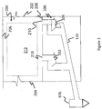
- FIG 1 depicts the solids flow control valve system 100 for a moving bed heat exchanger 200 that comprises a plurality of valves 102, 104.
- each valve 102, 104 comprises a standpipe 112, a shoe 126, and a housing 116.
- hot solids and/or ash from the moving bed heat exchanger 200 travel from the moving bed heat exchanger through the valve 102 into a transport conduit 120 to a combustion chamber 976.
- the hot solids and/or ash travels from the moving bed heat exchanger 200 through the standpipe 112, the shoe 126 and the housing 116 before entering the transport conduit 120 from which they are transported to the combustion chamber 976.
- the combustion chamber 976 may be replaced by a reactor (not shown) or a hopper (not shown) which facilitates disposal of the hot solids and/or ashes.
- the solids flow control valve system 100 is disposed downstream of the moving bed heat exchanger 200 and in operative communication with it.
- the solids flow control valve system 100 is generally located upstream of the combustion chamber 976 (or alternatively the reactor or the hopper).
- the solids flow control valve system 100 is disposed directly below the moving bed heat exchanger 200 and contacts an opening in the floor of the moving bed heat exchanger.
- the moving bed heat exchanger 200 comprises an enclosure 202 that contains a number of tubes (not shown) which are arranged in one or more heat exchanger tube bundles 212.
- the enclosure 202 is formed by vertical walls 204 of the moving bed heat exchanger, a roof 206 that contacts the vertical walls and a floor 208 that also contacts the vertical walls 204.
- the moving bed heat exchanger receives hot solids and/or ashes from a boiler cyclone loop seal, the combustion chamber, the reactor, the hopper, or a similar source of hot granular solids.
- the tube bundles 212 in the moving bed heat exchanger 200 are arranged to remove heat from the hot solids and/or ashes and to transfer it to a cooling medium.
- the cooling medium is generally water, steam, thermal oil, or heat transfer coolant.
- the heating or cooling medium flows through the tubes.
- Cooling medium and product e.g., hot solids and/or ash
- the coolers work according to the moving bed principle, i.e., the hot solids and/or ash forms a product column which flows continuously downwards between the cooling tubes. Heat is transferred from the ash or solids through the tube walls to the cooling fluid.
- hot solids and/or ash from the moving bed heat exchanger 200 flows downwards between the tubes (not shown) towards the solids flow control valves 102 and 104.
- the Figure 2 depicts a single valve 102.
- the valve 102 comprises a standpipe 112 that is operative to transport hot solids and/or ash from the moving bed heat exchanger 200 to a combustion chamber 976 or to a reactor(not shown) or to a hopper (not shown) via an inclined transport conduit 120.
- the standpipe also serves as a pressure seal between the higher pressure transport pipe and the lower pressure moving bed heat exchanger.
- the upper end of the standpipe 112 contacts the floor 208 of the moving bed heat exchanger 200.
- the floor 208 contains a plurality of holes 210 which are lined up with an opening of the standpipe 112.
- the standpipe 112 and the hole 210 are coaxial and are concentrically aligned.
- the upper end of the standpipe 112 may contact the floor 208 via an optional flange 124.
- the flange 124 permits the valve to be removed for maintenance and for replacement if desired.
- the end of the standpipe 112 opposite the upper end contacts a flow control shoe 126 (hereinafter shoe 126) into which the hot solids and/or ashes that are transported through the standpipe 112 are deposited.
- the shoe 126 lies downstream of the standpipe 112.
- the shoe 126 may be a monolithic part of the standpipe 112 or it may be fixedly attached to the standpipe 112 by rivets, by welding, or the like.
- the shoe 126 may be reversibly attached to the transport conduit by screw threads or by bolts and nuts.
- the shoe 126 discharges.its contents into a housing 116 and to a transport pipe 120.
- the transport pipe 120 is located downstream of the shoe 126.
- An optional expansion joint 125 may be installed in the standpipe to accommodate thermal expansion differences between the moving bed heat exchanger 208 and the transport pipe 120.
- the standpipe 112 is vertical. However, it is also possible to incline the standpipe at angles other than the vertical.
- the standpipe generally transports solids from the moving bed heat exchanger to the combustion chamber 976 or reactor of hopper under the effect of gravity and it is therefore desirable for the standpipe to be positioned in such a manner so as to permit gravity to facilitate the movement of solids from the moving bed heat exchanger to combustion chamber 976 or alternatively to a reactor or to a hopper.
- gravity even when the standpipe is inclined at angles other than the vertical, it is desirable for gravity to be able to effect the downward flow of solids.
- the height of the standpipe is determined by the design back pressure between the combustion chamber or discharge hopper and the moving bed heat exchanger 200. Back pressures less than the design value will permit ash or solids to be discharged to the transport pipe 120.
- the Figure 3 is an enlarged depiction of the shoe 126.
- the Figure 3 depicts a side view and a back view. Neither the side view nor the back view in the Figure 3 are drawn to scale.
- the shoe 126 contains a back face 128 (hereinafter the heel 128) that is aligned with the standpipe 112 such that the inner wall of the standpipe is flush with the inner face of the heel 128.
- Affixed to the heel 128 is a first port 118 containing a sintered frit, through which pressurized air may be admitted into the shoe 126.
- the base of the shoe 126 contains a porous sintered frit 122 through which low pressurized air may be admitted into the shoe 126.
- the base of the shoe 126 acts as a temporary restraint to the downwards flow of the hot solids and/or ash. As the hot solids and/or ash flows downwards under gravity, it meets the base of the shoe 126 and begins to pile up in the shoe. The base of the shoe 126 thus acts as a control on the downward flow of hot solids and/or ash.
- the shoe 126 has opposing side walls 132 and 134, each of which contacts the heel 128, the base of the shoe and the toe 114 of the shoe.
- the side walls 132, 134 extend above the top of the toe 114 when measured from the bottom of the base of the shoe 126.
- a housing 116 completes the shoe 126.
- the side walls 132, 134 of the of the shoe form side walls for the housing 116 and contact the roof 140 of the housing.
- the housing 116 has a front wall 162 and a rear wall 160.
- the front wall 162 contacts the roof 140 of the housing, while the rear wall 160 contacts the base 122 of the shoe 126 as shown in the Figure 3 .
- the housing 116 thus prevents hot solids and/or ashes that are transported to the shoe from falling out of the solids control valve system.
- the passages in the shoe 126, the passages between the toe 114 of the shoe 126 and the roof 140 or walls 160 of the housing 116, and the passages within the housing 116 are at least 3 times greater, specifically at least 5 times greater than the largest debris that are transported through the valve control system.
- the passages in the shoe 126, the passages between the toe 114 of the shoe 126 and the roof 140 or walls 160 of the housing 116, and the passages within the housing 116 are at least 5 times greater than the largest debris that are transported through the valve control system. Having the passages be at least 3 times larger than the largest debris that can be transported in the system, facilitates a smooth movement of the hot solids and/or ashes and prevents clogging of the solids flow control system.
- the first port 118 in the shoe 126 serves as an inlet port for pressurized air that is intended to dislodge large debri present in the high temperature solids and/or ash.
- the hot solids and/or ash that are discharged from the moving bed heat exchanger may contain occasional large debris that can cause clogging of the valves 102, 104.
- pressurized air is periodically discharged through the valves through the first port 118 and also the base 122 at flow rates greater than needed for steady operation.
- the high pressure air is discharged through the valve for periods of about 5 to about 20 seconds at intervals of about 30 seconds to about 40 seconds.
- the base of the shoe 126 contains a porous sintered frit 122 through which low pressurized air may be admitted into the shoe 126.
- the sintered frit may be manufactured from a ceramic or from a metal that does not react with any of the hot solids, ashes or the hot gases that are discharged through the valve 102.
- the porous sintered frit may be replaced with a pad of sintered mesh that has a minimal pressure drop.
- the sintered frit or the pad of sintered mesh may have a pore size of about 3 micrometers to about 10 micrometers.
- the average particle size of ash particles or hot solids is about 50 to about 200 micrometers and the bulk of these particles cannot pass through the porous frit or the pad of sintered mesh.
- a drain in the plenum supplying air to the frit permits the evacuation of fines that might pass through the frit.
- the presence of a porous frit or a pad of sintered mesh located at the base of the shoe facilitates the uniform flow of hot solids and ash through the shoe because of a stream of low pressure air admitted into the shoe via the porous frit or the mesh 122.
- the low pressure air fluidizes the hot solids or ash and facilitates the uniform transportation of hot solids and/or ash from the shoe 126 into the transport pipe 112.
- the stream of low pressure air may be continuous or may be intermittent.
- the low pressure air may be admitted into the shoe via a portion of the base (i.e., it may be allowed to enter the shoe via the forward portion or through the rear portion of the frit.) In other words, the low pressure air may be admitted into the shoe at a variety of different positions and at a variety of different angles.
- the low pressure air is generally admitted through the porous sintered frit 122 at a pressure of about 0.08 to about 0.23 kilogram per square centimeter.
- the toe 114 is opposed to the heel 128 and the inner surface of the toe 114 is inclined to the base by an angle ⁇ that is greater than 90 degrees. The angle ⁇ that ranges from about 105 to about 135 degrees.
- the housing 116 covers the shoe 126 and directs the hot solids and/or hot ashes from the shoe to the transport pipe 120.
- the housing 116 is in a protective relationship with the shoe 128 and surrounds the shoe 128.
- the housing 116 contacts the shoe and the transport pipe and provides a fluid communication pathway between the shoe and the transport pipe. It prevents hot solids and/or ashes from dispersing into the environment around the valves.
- the transport pipe 120 is inclined at an angle effective to transport the fluidized hot solids and/or fluidized ashes to the combustion chamber 976 or to a hopper.
- the transport pipe is inclined at an angle ⁇ with respect to a vertical.
- the angle ⁇ is varied at an angle of about 60 degrees to about 120 degrees measured clockwise or anti-clockwise with respect to the vertical.
- the solids flow control valves 102 and 104 function to control the flow of hot solids and/or ash by creating a tortuous pathway between the shoe 126 and the housing 116.
- the tortuous pathway causes the solids to flow in at least two different directions from the moving bed heat exchanger to the combustion chamber or the reactor or the hopper.
- the hot solids and/or ashes flow in a first direction and upon contacting the base of the shoe, the hot solids and/or ashes change direction and flow in a second direction towards the toe of the shoe.
- the hot solids and/or ashes Upon moving across the toe 114 of the shoe, the hot solids and/or ashes once again change direction and flow in a third direction towards the transport pipe 120.
- the tenuous pathway created in the shoe 126 is thus used to regulate the flow of solids.
- the transport pipe 120 may have a diameter of about 25 centimeters to about 500 centimeters. It is to be noted that the transport pipe has a diameter that is at least 3 times, specifically at least 4 times, and more specifically at least 5 times greater than the largest debris that may be transported from the moving bed heat exchanger to the combustion chamber or to the hopper or to the reactor. As may be seen in the Figure 1 , one or more valves may be in operative communication with the transport pipe 120. It is to be noted that while the Figure 1 , depicts two valves, the air flow control valve system may have about 1 to about 50 valves, specifically about 5 to about 25 valves, and more specifically about 4 to about 16 valves. In an exemplary embodiment, the solids flow control valve system has about 16 valves. The number of valves may be dependent on the cross-sectional area of the moving bed heat exchanger 200.
- the valves are arranged adjacent to each other in a plurality of rows. Each row is in communication with a transport pipe.
- a single or plurality of transport pipes may be used to connect the plurality of rows of valves with the combustion chamber or with a hopper.
- valves when an air flow control valve system has 16 valves, the valves may be arranged in 4 rows each having 4 valves. The system will then have 16 standpipes, 16 shoes and 16 covers, each standpipe being associated with a shoe and a cover. The 4 valves in each row will be connected to a transport pipe 120. The system will have 1 or 4 transport pipes, each of which will transport the solids or ashes to the combustion chamber or to the hopper.
- the standpipe, the shoe, the housing, the transport pipe are all manufactured from materials that do not react with the hot solids or gases produced in the combustion chamber.
- the parts of the valve may be manufactured from metals, refractories, or a combination thereof. Metal parts that are coated with ceramics can also be used.
- valve system disclosed herein has a number of advantages. It has no moving parts as a result of which maintenance is greatly reduced over other comparable valves that have moving parts (e.g., ball valves, gate valves, sluice valves).
- a wide range of ash or solids flow control is obtained by a digital sequencing of the air supplied to the valves 102, 104.
- the pressurized air is discharged through the valve for periods of about 5 to about 20 seconds at intervals of about 30 seconds to about 40 seconds. The precise intervals depend on the desired ash flow through the valves.
- the valves can be sequenced or operated individually to provide the desired ash flow and ash distribution through the moving bed heat exchanger standpipe
- the ash flow through the ash flow control valve system does not change.
- the system is thus self-controlling by the air supply sequencing described above.
- the back pressure limit is controlled by the ash bulk density and the height "h" of the standpipe above the shoe inlet. By setting the height "h" of the standpipe the flow rate of the hot solids and/or ashes can be controlled by adjusting the air flow to ports 118 and 122.
- the plurality of solids flow control valves 102, 104, and so on provide a uniform ash flow profile through the moving bed heat exchanger by controlling the flow of each flow control valve. It also allows for the use of a plurality of solids flow control valves, because it enables operation of the solids flow control valves in such a manner as to effect a uniform solids flow control through the valves. This in turn allows for uniform solids flow across the moving bed heat exchanger and for a uniform temperature profile across the moving bed heat exchanger.
- the active grids solids distributor allows for control of the flow of hot solids and/or ash through the moving bed heat exchanger with no moving parts, can use low pressure control and transport air from a primary air (PA) or secondary air (SA) fan (not shown), and can accommodate and pass the occasional piece of oversize rubble through the ash control valve.
- PA primary air
- SA secondary air
- the active grid solids distributor is reliable because it has no moving parts, which minimizes maintenance and improves reliability.
- the ash flow through an individual solids flow control valve is controlled by pulsing of air flow through the valve.
- Digital air flow control may be accomplished via the programmable logic controller.
- the programmable logic controller may use a microprocessor computer or a distributed control system. Secondary means of solids flow control can be attained by varying the control air flow rates during each pulse. The heat transfer of the moving bed heat exchanger tube bundle is not affected by this intermittent flow of ash.
- the active grids solids distributor refers to a plurality of ash control valves that are operated in a prescribed manner to control the total solids flow rate and solids flow distribution throughout the moving bed heat exchanger.
- the activation air flow is alternated among each of the solids flow control valves in the active grids solids distributor in a prescribed pattern so that each ash control valve in succession is actuated.
- Flow control variation between the ash control valves is obtained by changing the time for air flow activation for each ash control valve.
- the total hot solids and/or ash flow through the moving bed heat exchanger is controlled by the dwell time between activation for each ash control valve.
- a programmable logic controller is in electrical communication with the solids flow control valve system and is used to set the air flow sequences for the ash control valves.
- the programmable logic controller may be a microprocessor, a computer, or the like.
- the activation and dwell times for the ash control valves can be adjusted to smooth out imbalances in solids flow through the moving bed heat exchanger. Depending upon the tube bundle arrangement in the moving bed heat exchanger, it may also be used to bias the solids flow distribution in the moving bed heat exchanger for coolant temperature control.
- the Figure 4 is a depiction of the active grids solids distributor 400.
- the active grids solids distributor 400 comprises programmable logic controller 402 in electrical communication with a temperature measuring device 404, a first solenoid valve 406, a second solenoid valve 406', a first air flow control valve 408 (that controls air flow to the solids flow control valves 102, 104, and so on), a second air flow control valve 408' and a fan (not shown) or a pump 410.
- the fan or pump 410 is operative to discharge air (such as the primary air source of the combustion chamber) into the shoe via the first port 118 or via the base 122.
- the air from the fan or the pump 410 is discharged via the first air flow control valve 408 and the first solenoid valve 406 into the first port 118 of the shoe 126 or via the second air flow control valve 408' and the second solenoid valve 406' into the base 122 of the shoe 126.
- the first solenoid valve 406 and the second solenoid valve 406' functions as an "on-off" valve, while the first air flow control valve 408 and the second air flow control valve 408' is operative to allow for the control of the effective flow of air to the shoe 126.
- Temperature information from the moving bed heat exchanger is received by the programmable logic controller 402, which then activates air to the respective solid flow control valves 102, 104, and so on.
- the temperature at various points in the moving bed heat exchanger 200 or the inlet and outlet fluid temperature of the fluid flowing into the tube bundles 212 is fed to the programmable logic controller 402.
- the programmable logic controller 402 may activate the air flow control valve 408 and the solenoid valve 406 to actuate the flow of solids in a particular solid flow control valve 102 or 104 and so on.
- the programmable logic controller 402 may use a variety of different forms of logic to control the solids flow control valves in the solids flow control system.
- active grids solids distributor 400 and the solids flow control valves are discussed in further detail below. While the active grids solids distributor 402 is shown functioning as a closed loop system, one of ordinary skill in the art would understand that the system may operate in an open loop mode.
- the actuation of the valves may be based upon a variety of parameters such as the temperature of water or steam in one or more pipes, the flow rate of water or steam in one or more pipes, the temperature profile of the moving bed heat exchanger, the load on the boiler, the ash profile, the desires of a particular user, the overall system profile, or the like, or a combination of at least one of the foregoing parameters.
- the active grid solids distributor can control 1 to about 50 valves, specifically about 5 to about 25 valves, and more specifically about 4 to about 24 valves.
- the active grid solids distributor can control hot solids and/or ash flow in an ash valve control system having about 16 valves. It is generally desirable to have an even number of valves.
- an active grid solids distributor can control 16 ash control valves.
- the active grid solids distributor will permit low pressure air in the first valve of the 16 valves for a period of about 3 to about 15 seconds, specifically about 5 to about 10 seconds, after which it is turned off for a period of 15 to about 50 seconds, specifically about 20 to about 30 seconds.
- the active grid solids distributor Upon turning off the first valve, the active grid solids distributor will permit low pressure air in the second valve of the 16 valves for a period of about 3 to about 15 seconds, specifically about 5 to about 10 seconds, after which it is turned off for a period of 15 to about 50 seconds, specifically about 20 to about 30 seconds. In this manner, the active grid solids distributor turns all 16 valves on and off sequentially, or in parallel. The process is then repeated.
- the valves may be activated sequentially in rows or in columns.
- the valves in the first row or first column may be activated prior to the valves in the second row or second column.
- the valves in a plurality of rows or columns may be activated simultaneously prior to the valves in another plurality of rows or columns being activated simultaneously.
- the valves in all of the rows or all of the columns may be activated simultaneously.
- the aforementioned sequences may be used for either the low pressure air or the high pressure air or for both of them.
- the low pressure air and the high pressure air may be alternated in a variety of sequences for the valves in different rows or in different columns.
- the valves may be activated in any desirable sequence. As discussed hereinbefore, the sequence of activation of the valves may be dependent on an input parameter to the controller 402 of function in an open loop mode with a predetermined sequence.
- this method of controlling the hot solids and/or ash flow maintains a uniform distribution of temperature across the moving bed heat exchanger.
- the solids flow control valves and the active grid solids distributor can be used in other types of heat exchangers where heat is to be extracted from hot solids and/or ash. It can also be used in other industries where control of solids flow is desired. For example, it can be used in industries involved in the manufacture of metals such as steel and aluminum, where irregularly shaped solids are to be charged to a furnace.
- This example depicts the functioning of the solids flow control valve and the solids flow control valve system. This example details the solids flow control valve and its operation using a low pressure air source.
- a commercial moving bed heat exchanger having a square cross-sectional area with sides of approximately 16 feet x 16 feet size was selected as a base for this experiment.
- a slice model was constructed to demonstrate the use of the ash control valve grid to control the ash flow through the slice.
- a series of nozzles were located under the slice model to connect with ash control valves.
- the ash control valves and the moving bed heat exchanger used for this experimental set-up are similar to that shown in the Figure 1 .
- the ash control valves were pneumatically actuated by a low-pressure air system. As explained above, each ash control valve was supplied with fluidizing air through a sintered mesh at the bottom or sole, and at the bottom of the inlet dip leg or heel.
- a house compressed air supply passed through a pressure-reducing valve to provide an air flow at 60 inches of water gage pressure.
- Several ash control valves could be fed by the air supply.
- Four ash control valves with two admission ports each were connected to the air supply.
- Each port had a flow control valve and an isolation ball valve to control airflow to the port. This permitted the flow to a single port to be set to a desired value and then turned on or off by the isolation ball valve without disturbing the flow setting.
- Two air admission ports were used to provide maximum ash flow rates; a bottom or sole air-port, and a standpipe or heel air-port. Initially several single openings of various orientation were tried for the air-port in order to determine the optimum location.
- the air ports were supplied with a pad of sintered mesh having minimal pressure drop and a pore size of the order of 5 micrometers.
- the pads were recessed in the bottom of a 1 ⁇ 4 inch deep opening and as such did not see the stream of ash flowing through the ash control valve.
- the use of the sintered pads with air flowing therethrough prevented backsifting of the ash into the air supply plenum.
- Each solids flow control valve discharged solids and/or ashes into a 2 inch transport pipe.
- the solids/and or ashes were discharged into a receiving hopper, which served as a replacement for the combustion chamber.
- Ash flow control by the ash control valve was basically on or off. Minor ash flow control could be obtained by adjusting the air flows. However in order to pass rubble through the ash control valve, the air flows needed to be maintained at high flow settings. Low ash flows were obtained by a digital on-off operation of the valves (typically 5 seconds with the air flow on followed by 25 second with the air flow off). If the on-off ratio was adjusted, the average ash flow would correspondingly change. The moving bed heat exchanger tube bundle heat transfer was not affected by this intermittent flow of ash.
- This example was conducted to demonstrate how the height "h" and diameter of a standpipe can be used to control the back pressure in the solids flow control valve.
- the height of the standpipe above the shoe determines how much back pressure can develop in the system.
- the height of the standpipe was increased by 10 inches with a 1.88 inch inner diameter tube extension into the slice model to provide increased backpressure flow capability.
- ash control valves were tested, all discharging into a common return transport tube as shown in Figure 1 .
- the ash control valves were of 2 inches dip leg size and of 3 inches dip leg size respectively. The size difference was selected to provide a size scale up for the ash control valve.
- the solids flow control valves all discharged into the 2 inch transport pipe. Several angles of inclination ⁇ from 15 degrees to 330 degrees for the transport pipe were evaluated. Two sizes of ash control valves were tested - a 2 inch diameter standpipe and a 3-inch diameter standpipe. Both sizes discharged into a 2-inch inner diameter transport pipe.
- Control air sequencing for the ash control valve and standpipe is shown in the Figure 5 .
- Low range pressure regulating valves were connected to a house compressed air supply. This provided an adjustable supply pressure for the ash control valves and for the transport pipe.
- the pressure regulators were set for ranges from 60 inches of H 2 O to 120 inches of H 2 O depending on the test requirements. Air flow to the ash control valve was measured by an orifice meter. Air flow to the transport tube was measured by a separate orifice meter having.
- Air flowing from the measurement orifice to the base of the solids flow control valve (the sintered pad) and heel ports (the first port) was controlled by a inch pipe needle valve and a inch ball valve.
- the major pressure drop in the air supply system was in the needle valve.
- the needle valve for each ash control valve was set with the others isolated by their ball valves so that the orifice meter measured the flow to that particular ash control valve.
- the needle valves were successively set for each port on each ash control valve and unchanged during a test.
- the primary characteristic of the ash control valve was the control of the sequential air flow rates needed for activation, the subsequent solids flow rate, the influence of the transport pipe inclination, and the effect of rubble or oversize particles on performance.
- Ash flow rate control by an ash control valve is primarily an on-off process. Secondary control is attained by varying the control air flow rates.
- the primary control method for moving bed heat exchanger application was to pulse the ash control valve by a digital air flow control, resulting in pulsed solids flow control. This pulsed flow control did not have a significant effect on heat transfer.
- Figure 6 shows all graphical depictions of the average ash control valve transport duct pressure drop versus the ash flow rate for various ash control valve sizes and transport duct inclination.
- the ash control valve control air was on continually at the beginning of the test, then was digitally pulsed 10 seconds on followed by 20 seconds off, then was pulsed 5 seconds on followed by 25 seconds off.
- the solids to air ratio for the ash control valve was determined to be of the order of 400 to 20,000 pounds solids/pound of air. This translates to about 20 to about 150 pounds per hour per square foot based on the standpipe cross-sectional area. In effect, the solids would flow if enough air was supplied to fluidize the material in the standpipe and the standpipe was of sufficient height.
- a pneumatic solids flow control valve can effectively control the flow rate and meet the capacity requirements of a moving bed heat exchanger.
- the final configuration tested contained sintered mesh control air fluidizing pads. Air injection ports without the sintered mesh pads were subject to ash backsifting and loss of flow capacity. The sintered pads never experienced backsifting or loss of flow.
- low pressure primary air could be used for control activation of the ash control valve, and for transport of the ash from the ash control valve to the combustion chamber, provided that transport pipes are sloped downward at an angle of inclination ⁇ of 60 to 120 degrees measured from a vertical.
- the solids flow control valves can transport from about 20,000 to about 400,000 pounds per hour per square foot of hot solids and/or ash with an ash to air weight ratio of 2000 or greater.
- a hot field test was conducted at an operating circulating fluidized bed (CFB) boiler site to demonstrate that the above concepts could be put into commercial practice.
- a moving bed heat exchanger slice model of 0.46 meter by 2.1 meter plan area cross section was installed to receive a slip stream of hot recycled ash from the CFB boiler.
- the moving bed heat exchanger and control valves were operated for an extended period of several cumulative months to demonstrate the ability to transfer design criteria from ambient conditions to hot operating conditions for an extended period of time.
- relative terms such as “lower” or “bottom” and “upper” or “top,” may be used herein to describe one element's relationship to another element as illustrated in the Figures. It will be understood that relative terms are intended to encompass different orientations of the device in addition to the orientation depicted in the Figures. For example, if the device in one of the figures is turned over, elements described as being on the “lower” side of other elements would then be oriented on “upper” sides of the other elements. The exemplary term “lower,” can therefore, encompasses both an orientation of “lower” and “upper,” depending on the particular orientation of the figure.
- Exemplary embodiments are described herein with reference to cross section illustrations that are schematic illustrations of idealized embodiments. As such, variations from the shapes of the illustrations as a result, for example, of manufacturing techniques and/or tolerances, are to be expected. Thus, embodiments described herein should not be construed as limited to the particular shapes of regions as illustrated herein but are to include deviations in shapes that result, for example, from manufacturing. For example, a region illustrated or described as flat may, typically, have rough and/or nonlinear features. Moreover, sharp angles that are illustrated may be rounded. Thus, the regions illustrated in the figures are schematic in nature and their shapes are not intended to illustrate the precise shape of a region and are not intended to limit the scope of the present claims.
Landscapes
- Engineering & Computer Science (AREA)
- Mechanical Engineering (AREA)
- General Engineering & Computer Science (AREA)
- Chemical & Material Sciences (AREA)
- Combustion & Propulsion (AREA)
- Physics & Mathematics (AREA)
- Thermal Sciences (AREA)
- Fluidized-Bed Combustion And Resonant Combustion (AREA)
- Separation By Low-Temperature Treatments (AREA)
- Compression-Type Refrigeration Machines With Reversible Cycles (AREA)
- Control Of Temperature (AREA)
- Heat-Exchange Devices With Radiators And Conduit Assemblies (AREA)
Priority Applications (2)
| Application Number | Priority Date | Filing Date | Title |
|---|---|---|---|
| HRP20160402TT HRP20160402T1 (hr) | 2010-10-28 | 2011-10-28 | Ventil za upravljanje protokom materijala iz izmjenjivača topline |
| PL11781929T PL2632831T3 (pl) | 2010-10-28 | 2011-10-28 | Zawór do sterowania przepływem materiału z wymiennika ciepła |
Applications Claiming Priority (5)
| Application Number | Priority Date | Filing Date | Title |
|---|---|---|---|
| US40774110P | 2010-10-28 | 2010-10-28 | |
| US40770610P | 2010-10-28 | 2010-10-28 | |
| US40769410P | 2010-10-28 | 2010-10-28 | |
| US13/283,355 US9617087B2 (en) | 2010-10-28 | 2011-10-27 | Control valve and control valve system for controlling solids flow, methods of manufacture thereof and articles comprising the same |
| PCT/US2011/058245 WO2012058520A1 (en) | 2010-10-28 | 2011-10-28 | Valve for controlling flow of material out of heat exchanger |
Publications (2)
| Publication Number | Publication Date |
|---|---|
| EP2632831A1 EP2632831A1 (en) | 2013-09-04 |
| EP2632831B1 true EP2632831B1 (en) | 2016-02-24 |
Family
ID=44936553
Family Applications (1)
| Application Number | Title | Priority Date | Filing Date |
|---|---|---|---|
| EP11781929.2A Not-in-force EP2632831B1 (en) | 2010-10-28 | 2011-10-28 | Valve for controlling flow of material out of heat exchanger |
Country Status (9)
| Country | Link |
|---|---|
| US (1) | US9617087B2 (pl) |
| EP (1) | EP2632831B1 (pl) |
| CN (1) | CN103269961B (pl) |
| ES (1) | ES2568727T3 (pl) |
| HR (1) | HRP20160402T1 (pl) |
| HU (1) | HUE028473T2 (pl) |
| PL (1) | PL2632831T3 (pl) |
| RS (1) | RS54703B1 (pl) |
| WO (1) | WO2012058520A1 (pl) |
Cited By (1)
| Publication number | Priority date | Publication date | Assignee | Title |
|---|---|---|---|---|
| CN106044044A (zh) * | 2016-07-14 | 2016-10-26 | 无锡派乐科技有限公司 | 一种物料输送通道 |
Families Citing this family (5)
| Publication number | Priority date | Publication date | Assignee | Title |
|---|---|---|---|---|
| JP5868839B2 (ja) * | 2012-12-27 | 2016-02-24 | 三菱重工業株式会社 | チャー払出管 |
| WO2014160667A1 (en) * | 2013-03-28 | 2014-10-02 | Nordson Corporation | Adhesive bin and method of storing and moving adhesive particulate to an adhesive melter |
| CN106144601A (zh) * | 2016-07-18 | 2016-11-23 | 无锡派乐科技有限公司 | 一种用于输送物料的通管 |
| CN106006037A (zh) * | 2016-07-18 | 2016-10-12 | 无锡派乐科技有限公司 | 一种可以清理磁性垃圾的管路 |
| CN105923400A (zh) * | 2016-07-18 | 2016-09-07 | 无锡派乐科技有限公司 | 一种高效输送管路结构 |
Citations (1)
| Publication number | Priority date | Publication date | Assignee | Title |
|---|---|---|---|---|
| US5682828A (en) * | 1995-05-04 | 1997-11-04 | Foster Wheeler Energy Corporation | Fluidized bed combustion system and a pressure seal valve utilized therein |
Family Cites Families (71)
| Publication number | Priority date | Publication date | Assignee | Title |
|---|---|---|---|---|
| US2316814A (en) * | 1940-03-08 | 1943-04-20 | Schemm Henry Ripley | Feeder |
| US2756981A (en) * | 1953-02-27 | 1956-07-31 | Kloeckner Humboldt Deutz Ag | Installation for the heating of fine granular material, especially cement raw material |
| DE1401704B2 (de) | 1962-08-22 | 1970-02-05 | Siemens AG, 1000 Berlin u. 8000 München | Wärmetauscher mit in Schüttung aneinanderliegenden wandernden Masseteilchen |
| GB1102264A (en) | 1966-02-01 | 1968-02-07 | Buell Engineering Company Inc | Method of and apparatus for coding or heating particulate material |
| CH449937A (de) | 1967-06-22 | 1968-01-15 | Buss Ag | Abscheide- und Kühlvorrichtung für Kunststoffgranulat |
| DE1920889A1 (de) | 1969-04-24 | 1970-11-19 | Siemens Ag | Masseteilchen-Waermetauscher |
| US3679271A (en) * | 1969-11-19 | 1972-07-25 | Brunswick Corp | Support for a fluidized bed |
| SE363346B (pl) | 1972-09-27 | 1974-01-14 | Asea Ab | |
| GB1523500A (en) * | 1975-10-21 | 1978-09-06 | Battelle Development Corp | Method of operating a fluidized bed system |
| US4307773A (en) | 1978-08-28 | 1981-12-29 | Smith Richard D | Fluid bed heat exchanger for contaminated gas |
| US4279207A (en) | 1979-04-20 | 1981-07-21 | Wormser Engineering, Inc. | Fluid bed combustion |
| US4479353A (en) | 1979-10-31 | 1984-10-30 | The Babcock & Wilcox Company | Moving bed heat storage and recovery system |
| FR2500610B1 (fr) | 1981-02-25 | 1986-05-02 | Inst Francais Du Petrole | Echangeur de chaleur a plaques perforees |
| CA1197074A (en) | 1981-12-04 | 1985-11-26 | Isaias Loukos | Method and apparatus for cleaning waste gases from aluminum production facilities |
| US4659340A (en) | 1985-06-24 | 1987-04-21 | Weaver Lloyd E | Pressurized downdraft gasifier |
| FR2587090B1 (fr) * | 1985-09-09 | 1987-12-04 | Framatome Sa | Chaudiere a lit fluidise circulant |
| DE3544425A1 (de) * | 1985-12-16 | 1987-06-25 | Steag Ag | Verfahren zum verbrennen von festen brennstoffen in einer zirkulierenden wirbelschicht und vorrichtung zum durchfuehren dieses verfahrens |
| US4687497A (en) * | 1986-09-29 | 1987-08-18 | Mobil Oil Corporation | Solids-gas separator |
| DE3714923A1 (de) * | 1987-05-05 | 1988-12-01 | Waeschle Maschf Gmbh | Vorrichtung zum pneumatischen foerdern von schuettgut |
| US4777889A (en) * | 1987-05-22 | 1988-10-18 | Smith Richard D | Fluidized bed mass burner for solid waste |
| US4869207A (en) * | 1987-07-13 | 1989-09-26 | A. Ahlstrom Corporation | Circulating fluidized bed reactor |
| CN1042412A (zh) | 1988-10-31 | 1990-05-23 | 东南大学 | 常压沸腾炉高温灰渣冷却器 |
| US5275788A (en) * | 1988-11-11 | 1994-01-04 | Peter Stoholm | Circulating fluidized bed reactor |
| FI85909C (fi) * | 1989-02-22 | 1992-06-10 | Ahlstroem Oy | Anordning foer foergasning eller foerbraenning av fast kolhaltigt material. |
| US4955295A (en) * | 1989-08-18 | 1990-09-11 | Foster Wheeler Energy Corporation | Method and system for controlling the backflow sealing efficiency and recycle rate in fluidized bed reactors |
| US5133943A (en) * | 1990-03-28 | 1992-07-28 | Foster Wheeler Energy Corporation | Fluidized bed combustion system and method having a multicompartment external recycle heat exchanger |
| DE4137853A1 (de) | 1991-11-16 | 1993-05-19 | Babcock Energie Umwelt | Verfahren und vorrichtung zum austragen von feststoff |
| US5339774A (en) * | 1993-07-06 | 1994-08-23 | Foster Wheeler Energy Corporation | Fluidized bed steam generation system and method of using recycled flue gases to assist in passing loopseal solids |
| ZA946850B (en) * | 1993-09-13 | 1995-04-21 | Dorr Oliver Inc | Firing liquid and gaseous fuels for a circulating fluidized bed reactor |
| US5676281A (en) * | 1994-03-28 | 1997-10-14 | Bhm Company | Fluid flow airlock valve |
| US6357517B1 (en) | 1994-07-04 | 2002-03-19 | Denso Corporation | Cooling apparatus boiling and condensing refrigerant |
| DE19508488C3 (de) * | 1995-03-09 | 2001-03-15 | Martin Umwelt & Energietech | Verfahren und Vorrichtung zum Erzeugen von deponiefähigen oder weiterverarbeitbaren Verbrennungsrückständen aus einer Abfallverbrennungsanlage |
| US6076596A (en) | 1996-03-14 | 2000-06-20 | Denso Corporation | Cooling apparatus for high-temperature medium by boiling and condensing refrigerant |
| DE19709934B4 (de) | 1996-03-14 | 2008-04-17 | Denso Corp., Kariya | Kühlgerät zum Sieden und Kondensieren eines Kältemittels |
| DE19629289A1 (de) | 1996-07-19 | 1998-01-22 | Umsicht Inst Fuer Umwelt Siche | Siphon zur Förderung feinkörniger Feststoffe |
| DE19723159C2 (de) | 1997-06-03 | 2002-06-06 | Siamant Ceramic Systems Gmbh & | Höchsttemperatur-Wärmetauscher auf Siamantbasis |
| CN1262791C (zh) * | 1998-06-16 | 2006-07-05 | 三菱重工业株式会社 | 流化床焚烧炉及其运行方法 |
| JP2000256856A (ja) | 1999-03-11 | 2000-09-19 | Tokyo Electron Ltd | 処理装置及び処理装置用真空排気システム及び減圧cvd装置及び減圧cvd装置用真空排気システム及びトラップ装置 |
| CN1117900C (zh) | 1999-06-28 | 2003-08-13 | 张永迪 | 有色衣物染色翻新方法 |
| EP1230515B1 (en) * | 1999-11-02 | 2006-12-27 | Consolidated Engineering Company, Inc. | Method and apparatus for combustion of residual carbon in fly ash |
| US6589778B1 (en) | 1999-12-15 | 2003-07-08 | Amersham Biosciences Ab | Method and apparatus for performing biological reactions on a substrate surface |
| US6293112B1 (en) | 1999-12-17 | 2001-09-25 | American Standard International Inc. | Falling film evaporator for a vapor compression refrigeration chiller |
| US6269778B1 (en) * | 1999-12-17 | 2001-08-07 | The Babcock & Wilcox Company | Fine solids recycle in a circulating fluidized bed |
| CA2328312C (en) | 2000-12-14 | 2010-12-07 | Herbert Rittberger | Heat exchanger |
| US6609871B2 (en) | 2001-06-18 | 2003-08-26 | Young Industries, Inc. | System for handling bulk particulate materials |
| JP2003161594A (ja) | 2001-09-14 | 2003-06-06 | Denso Corp | 沸騰冷却装置 |
| TW571049B (en) * | 2001-11-12 | 2004-01-11 | Ishikawajima Harima Heavy Ind | Circulating fluidized bed boiler |
| US6684917B2 (en) * | 2001-12-17 | 2004-02-03 | The University Of Western Ontario | Apparatus for volumetric metering of small quantity of powder from fluidized beds |
| US6719500B2 (en) | 2002-08-20 | 2004-04-13 | The Young Industries, Inc. | System for pneumatically conveying bulk particulate materials |
| DE10300838A1 (de) | 2003-01-10 | 2004-07-22 | Alstom Power Boiler Gmbh | Zirkulierender Wirbelschichteaktor |
| US6764253B1 (en) * | 2003-02-14 | 2004-07-20 | The Young Industries, Inc. | System and method for assuring fluidization of a material transported in a pneumatic conveying system |
| GB0316864D0 (en) * | 2003-07-18 | 2003-08-20 | Linertech Ltd | Improvements in and relating to container liners |
| US7343965B2 (en) | 2004-01-20 | 2008-03-18 | Modine Manufacturing Company | Brazed plate high pressure heat exchanger |
| TW200537695A (en) | 2004-03-19 | 2005-11-16 | Adv Lcd Tech Dev Ct Co Ltd | Insulating film forming method, insulating film forming apparatus, and plasma film forming apparatus |
| US6868695B1 (en) | 2004-04-13 | 2005-03-22 | American Standard International Inc. | Flow distributor and baffle system for a falling film evaporator |
| US7740026B2 (en) | 2004-06-28 | 2010-06-22 | Taikisha Ltd. | Thermal storage type gas treating apparatus |
| FI116417B (fi) * | 2004-07-01 | 2005-11-15 | Kvaerner Power Oy | Kiertoleijukattila |
| WO2006064014A1 (en) * | 2004-12-17 | 2006-06-22 | Shell Internationale Research Maatschappij B.V. | Pipe part for conveying a solid particulate material |
| US7410619B2 (en) | 2004-12-29 | 2008-08-12 | Utc Power Corporation | Catalytic combustors keeping contained medium warm in response to hydrostatic valve |
| WO2007009713A1 (de) | 2005-07-19 | 2007-01-25 | Behr Gmbh & Co. Kg | Wärmeübertrager |
| ES2294741T3 (es) | 2006-02-07 | 2008-04-01 | Ibau Hamburg Ingenieurgesellschaft | Dispositivo de transporte neumatico de material pulverulento. |
| US7937943B2 (en) | 2006-12-22 | 2011-05-10 | Yiding Cao | Heat engines |
| DE102007009759A1 (de) * | 2007-02-27 | 2008-08-28 | Outotec Oyj | Verfahren und Vorrichtung zur Aufteilung eines Feststoffstromes |
| GB0705439D0 (en) | 2007-03-22 | 2007-05-02 | Alstom Intellectual Property | Improved flue gas cooling and cleaning arrangment |
| US7553111B2 (en) * | 2007-06-28 | 2009-06-30 | Flsmidth A/S | Fluidizing gravity conveyor with high temperature multi-layered fluid distributor member |
| FR2918975B1 (fr) | 2007-07-19 | 2009-11-20 | Alcan Int Ltd | Procede permettant de convoyer sans segregation des materiaux pulverulents |
| US9163829B2 (en) | 2007-12-12 | 2015-10-20 | Alstom Technology Ltd | Moving bed heat exchanger for circulating fluidized bed boiler |
| US8753044B2 (en) | 2008-06-09 | 2014-06-17 | Uop Llc | L-valve construction for controlling solids flow in a liquid medium using standard pipe fittings |
| MX2011009109A (es) | 2009-03-03 | 2011-10-19 | Harol Dean Curtis | Enfriador/torre de enfriamiento de fluido de tiro forzado directo y colector de liquido para el mismo. |
| JP5474193B2 (ja) | 2010-07-12 | 2014-04-16 | 株式会社アルバック | 成膜装置 |
| EP2489421B1 (en) | 2011-02-18 | 2021-03-31 | General Electric Technology GmbH | A wet scrubber for cleaning an effluent gas comprising an inlet gas distributor with a diffusor |
-
2011
- 2011-10-27 US US13/283,355 patent/US9617087B2/en not_active Expired - Fee Related
- 2011-10-28 RS RS20160239A patent/RS54703B1/sr unknown
- 2011-10-28 HU HUE11781929A patent/HUE028473T2/en unknown
- 2011-10-28 EP EP11781929.2A patent/EP2632831B1/en not_active Not-in-force
- 2011-10-28 PL PL11781929T patent/PL2632831T3/pl unknown
- 2011-10-28 HR HRP20160402TT patent/HRP20160402T1/hr unknown
- 2011-10-28 WO PCT/US2011/058245 patent/WO2012058520A1/en not_active Ceased
- 2011-10-28 ES ES11781929.2T patent/ES2568727T3/es active Active
- 2011-10-28 CN CN201180063296.6A patent/CN103269961B/zh not_active Expired - Fee Related
Patent Citations (1)
| Publication number | Priority date | Publication date | Assignee | Title |
|---|---|---|---|---|
| US5682828A (en) * | 1995-05-04 | 1997-11-04 | Foster Wheeler Energy Corporation | Fluidized bed combustion system and a pressure seal valve utilized therein |
Cited By (1)
| Publication number | Priority date | Publication date | Assignee | Title |
|---|---|---|---|---|
| CN106044044A (zh) * | 2016-07-14 | 2016-10-26 | 无锡派乐科技有限公司 | 一种物料输送通道 |
Also Published As
| Publication number | Publication date |
|---|---|
| HUE028473T2 (en) | 2016-12-28 |
| RS54703B1 (sr) | 2016-08-31 |
| WO2012058520A1 (en) | 2012-05-03 |
| HRP20160402T1 (hr) | 2016-05-20 |
| PL2632831T3 (pl) | 2016-07-29 |
| ES2568727T3 (es) | 2016-05-04 |
| CN103269961A (zh) | 2013-08-28 |
| US9617087B2 (en) | 2017-04-11 |
| US20120111243A1 (en) | 2012-05-10 |
| EP2632831A1 (en) | 2013-09-04 |
| CN103269961B (zh) | 2016-06-15 |
Similar Documents
| Publication | Publication Date | Title |
|---|---|---|
| EP2632831B1 (en) | Valve for controlling flow of material out of heat exchanger | |
| KR100376560B1 (ko) | 유동층 건조·분급장치 | |
| JP3830164B2 (ja) | 粒状材料床の処理方法及び装置 | |
| RU2002118783A (ru) | Циркулирующий пвсевдоожиженный слой с управляемым внутрислойным теплообменником | |
| KR20010033831A (ko) | 다챔버형 유동층분급장치 | |
| US10018353B2 (en) | Sealpot and method for controlling a solids flow rate therethrough | |
| CN104837549B (zh) | 具有提高的可靠性的床内固体控制阀 | |
| JP2009148747A (ja) | 流動化された粒子状固体の多段式処理のための方法及びシステム | |
| NO158936B (no) | Innretning for oekning av oksygenkonsentrasjonen i et undervannslag i en termisk lagdelt vannmasse. | |
| JP3037680B1 (ja) | 多室型流動層分級装置 | |
| EP0084887B1 (en) | Solids flow regulator | |
| US9557115B2 (en) | Orifice plate for controlling solids flow, methods of use thereof and articles comprising the same | |
| EP1230007A1 (en) | A fluidized bed apparatus | |
| US4805405A (en) | Power plant with combustion of a fuel in a fluidized bed | |
| US4203391A (en) | Fluidized bed fuel feeder | |
| CA2308500C (en) | Method and apparatus for controlling heat transfer from solid particles in a fluidized bed | |
| JPS5832136B2 (ja) | 粉粒体の気密排出装置 | |
| JP2807218B2 (ja) | 熱交換装置およびその運転方法 | |
| Armatsombat et al. | An Investigation of Characteristics of a Loop Seal with and without Side Aeration | |
| Basu | Air Distribution Grate | |
| JPS5879535A (ja) | 底部移送路を有する流動床 | |
| TH17772B (th) | เครื่องควบคุมปริมาณการเคลื่อนที่ของอนุภาค | |
| TH37869A (th) | เครื่องควบคุมปริมาณการเคลื่อนที่ของอนุภาค | |
| ITTO20011089A1 (it) | Impianto a letto fluidizzato per il trattamento di materiali di rifiuto. |
Legal Events
| Date | Code | Title | Description |
|---|---|---|---|
| PUAI | Public reference made under article 153(3) epc to a published international application that has entered the european phase |
Free format text: ORIGINAL CODE: 0009012 |
|
| 17P | Request for examination filed |
Effective date: 20130523 |
|
| AK | Designated contracting states |
Kind code of ref document: A1 Designated state(s): AL AT BE BG CH CY CZ DE DK EE ES FI FR GB GR HR HU IE IS IT LI LT LU LV MC MK MT NL NO PL PT RO RS SE SI SK SM TR |
|
| DAX | Request for extension of the european patent (deleted) | ||
| 17Q | First examination report despatched |
Effective date: 20140220 |
|
| GRAP | Despatch of communication of intention to grant a patent |
Free format text: ORIGINAL CODE: EPIDOSNIGR1 |
|
| INTG | Intention to grant announced |
Effective date: 20150904 |
|
| GRAS | Grant fee paid |
Free format text: ORIGINAL CODE: EPIDOSNIGR3 |
|
| GRAA | (expected) grant |
Free format text: ORIGINAL CODE: 0009210 |
|
| AK | Designated contracting states |
Kind code of ref document: B1 Designated state(s): AL AT BE BG CH CY CZ DE DK EE ES FI FR GB GR HR HU IE IS IT LI LT LU LV MC MK MT NL NO PL PT RO RS SE SI SK SM TR |
|
| REG | Reference to a national code |
Ref country code: GB Ref legal event code: FG4D |
|
| REG | Reference to a national code |
Ref country code: CH Ref legal event code: EP |
|
| REG | Reference to a national code |
Ref country code: AT Ref legal event code: REF Ref document number: 776573 Country of ref document: AT Kind code of ref document: T Effective date: 20160315 |
|
| REG | Reference to a national code |
Ref country code: IE Ref legal event code: FG4D |
|
| REG | Reference to a national code |
Ref country code: DE Ref legal event code: R096 Ref document number: 602011023456 Country of ref document: DE |
|
| REG | Reference to a national code |
Ref country code: HR Ref legal event code: TUEP Ref document number: P20160402 Country of ref document: HR |
|
| REG | Reference to a national code |
Ref country code: RO Ref legal event code: EPE |
|
| REG | Reference to a national code |
Ref country code: ES Ref legal event code: FG2A Ref document number: 2568727 Country of ref document: ES Kind code of ref document: T3 Effective date: 20160504 |
|
| REG | Reference to a national code |
Ref country code: HR Ref legal event code: T1PR Ref document number: P20160402 Country of ref document: HR |
|
| REG | Reference to a national code |
Ref country code: LT Ref legal event code: MG4D |
|
| REG | Reference to a national code |
Ref country code: NL Ref legal event code: MP Effective date: 20160224 |
|
| REG | Reference to a national code |
Ref country code: AT Ref legal event code: MK05 Ref document number: 776573 Country of ref document: AT Kind code of ref document: T Effective date: 20160224 |
|
| PG25 | Lapsed in a contracting state [announced via postgrant information from national office to epo] |
Ref country code: GR Free format text: LAPSE BECAUSE OF FAILURE TO SUBMIT A TRANSLATION OF THE DESCRIPTION OR TO PAY THE FEE WITHIN THE PRESCRIBED TIME-LIMIT Effective date: 20160525 Ref country code: IT Free format text: LAPSE BECAUSE OF FAILURE TO SUBMIT A TRANSLATION OF THE DESCRIPTION OR TO PAY THE FEE WITHIN THE PRESCRIBED TIME-LIMIT Effective date: 20160224 Ref country code: NO Free format text: LAPSE BECAUSE OF FAILURE TO SUBMIT A TRANSLATION OF THE DESCRIPTION OR TO PAY THE FEE WITHIN THE PRESCRIBED TIME-LIMIT Effective date: 20160524 Ref country code: FI Free format text: LAPSE BECAUSE OF FAILURE TO SUBMIT A TRANSLATION OF THE DESCRIPTION OR TO PAY THE FEE WITHIN THE PRESCRIBED TIME-LIMIT Effective date: 20160224 |
|
| RAP2 | Party data changed (patent owner data changed or rights of a patent transferred) |
Owner name: GENERAL ELECTRIC TECHNOLOGY GMBH |
|
| PG25 | Lapsed in a contracting state [announced via postgrant information from national office to epo] |
Ref country code: NL Free format text: LAPSE BECAUSE OF FAILURE TO SUBMIT A TRANSLATION OF THE DESCRIPTION OR TO PAY THE FEE WITHIN THE PRESCRIBED TIME-LIMIT Effective date: 20160224 Ref country code: PT Free format text: LAPSE BECAUSE OF FAILURE TO SUBMIT A TRANSLATION OF THE DESCRIPTION OR TO PAY THE FEE WITHIN THE PRESCRIBED TIME-LIMIT Effective date: 20160624 Ref country code: SE Free format text: LAPSE BECAUSE OF FAILURE TO SUBMIT A TRANSLATION OF THE DESCRIPTION OR TO PAY THE FEE WITHIN THE PRESCRIBED TIME-LIMIT Effective date: 20160224 Ref country code: AT Free format text: LAPSE BECAUSE OF FAILURE TO SUBMIT A TRANSLATION OF THE DESCRIPTION OR TO PAY THE FEE WITHIN THE PRESCRIBED TIME-LIMIT Effective date: 20160224 Ref country code: LT Free format text: LAPSE BECAUSE OF FAILURE TO SUBMIT A TRANSLATION OF THE DESCRIPTION OR TO PAY THE FEE WITHIN THE PRESCRIBED TIME-LIMIT Effective date: 20160224 Ref country code: LV Free format text: LAPSE BECAUSE OF FAILURE TO SUBMIT A TRANSLATION OF THE DESCRIPTION OR TO PAY THE FEE WITHIN THE PRESCRIBED TIME-LIMIT Effective date: 20160224 |
|
| REG | Reference to a national code |
Ref country code: DE Ref legal event code: R082 Ref document number: 602011023456 Country of ref document: DE Representative=s name: RUEGER | ABEL PATENT- UND RECHTSANWAELTE, DE Ref country code: DE Ref legal event code: R082 Ref document number: 602011023456 Country of ref document: DE Representative=s name: RUEGER ABEL PATENTANWAELTE PARTGMBB, DE Ref country code: DE Ref legal event code: R082 Ref document number: 602011023456 Country of ref document: DE Representative=s name: RUEGER, BARTHELT & ABEL, DE Ref country code: DE Ref legal event code: R081 Ref document number: 602011023456 Country of ref document: DE Owner name: GENERAL ELECTRIC TECHNOLOGY GMBH, CH Free format text: FORMER OWNER: ALSTOM TECHNOLOGY LTD., BADEN, CH Ref country code: DE Ref legal event code: R082 Ref document number: 602011023456 Country of ref document: DE Representative=s name: RUEGER ABEL PATENT- UND RECHTSANWAELTE, DE |
|
| REG | Reference to a national code |
Ref country code: HR Ref legal event code: ODRP Ref document number: P20160402 Country of ref document: HR Payment date: 20161012 Year of fee payment: 6 |
|
| REG | Reference to a national code |
Ref country code: HU Ref legal event code: HC9C Owner name: . GENERAL ELECTRIC TECHNOLOGY GMBH, CH Free format text: FORMER OWNER(S): ALSTOM TECHNOLOGY LTD, CH |
|
| PG25 | Lapsed in a contracting state [announced via postgrant information from national office to epo] |
Ref country code: DK Free format text: LAPSE BECAUSE OF FAILURE TO SUBMIT A TRANSLATION OF THE DESCRIPTION OR TO PAY THE FEE WITHIN THE PRESCRIBED TIME-LIMIT Effective date: 20160224 Ref country code: EE Free format text: LAPSE BECAUSE OF FAILURE TO SUBMIT A TRANSLATION OF THE DESCRIPTION OR TO PAY THE FEE WITHIN THE PRESCRIBED TIME-LIMIT Effective date: 20160224 |
|
| REG | Reference to a national code |
Ref country code: DE Ref legal event code: R097 Ref document number: 602011023456 Country of ref document: DE |
|
| PG25 | Lapsed in a contracting state [announced via postgrant information from national office to epo] |
Ref country code: CZ Free format text: LAPSE BECAUSE OF FAILURE TO SUBMIT A TRANSLATION OF THE DESCRIPTION OR TO PAY THE FEE WITHIN THE PRESCRIBED TIME-LIMIT Effective date: 20160224 Ref country code: SM Free format text: LAPSE BECAUSE OF FAILURE TO SUBMIT A TRANSLATION OF THE DESCRIPTION OR TO PAY THE FEE WITHIN THE PRESCRIBED TIME-LIMIT Effective date: 20160224 Ref country code: SK Free format text: LAPSE BECAUSE OF FAILURE TO SUBMIT A TRANSLATION OF THE DESCRIPTION OR TO PAY THE FEE WITHIN THE PRESCRIBED TIME-LIMIT Effective date: 20160224 |
|
| REG | Reference to a national code |
Ref country code: HU Ref legal event code: AG4A Ref document number: E028473 Country of ref document: HU |
|
| PG25 | Lapsed in a contracting state [announced via postgrant information from national office to epo] |
Ref country code: BE Free format text: LAPSE BECAUSE OF FAILURE TO SUBMIT A TRANSLATION OF THE DESCRIPTION OR TO PAY THE FEE WITHIN THE PRESCRIBED TIME-LIMIT Effective date: 20160224 |
|
| PLBE | No opposition filed within time limit |
Free format text: ORIGINAL CODE: 0009261 |
|
| STAA | Information on the status of an ep patent application or granted ep patent |
Free format text: STATUS: NO OPPOSITION FILED WITHIN TIME LIMIT |
|
| PGFP | Annual fee paid to national office [announced via postgrant information from national office to epo] |
Ref country code: GB Payment date: 20161027 Year of fee payment: 6 Ref country code: DE Payment date: 20161027 Year of fee payment: 6 |
|
| 26N | No opposition filed |
Effective date: 20161125 |
|
| PG25 | Lapsed in a contracting state [announced via postgrant information from national office to epo] |
Ref country code: SI Free format text: LAPSE BECAUSE OF FAILURE TO SUBMIT A TRANSLATION OF THE DESCRIPTION OR TO PAY THE FEE WITHIN THE PRESCRIBED TIME-LIMIT Effective date: 20160224 Ref country code: BG Free format text: LAPSE BECAUSE OF FAILURE TO SUBMIT A TRANSLATION OF THE DESCRIPTION OR TO PAY THE FEE WITHIN THE PRESCRIBED TIME-LIMIT Effective date: 20160524 |
|
| PGFP | Annual fee paid to national office [announced via postgrant information from national office to epo] |
Ref country code: RS Payment date: 20161005 Year of fee payment: 6 Ref country code: ES Payment date: 20161026 Year of fee payment: 6 Ref country code: HR Payment date: 20161012 Year of fee payment: 6 Ref country code: RO Payment date: 20161006 Year of fee payment: 6 |
|
| REG | Reference to a national code |
Ref country code: CH Ref legal event code: PL |
|
| REG | Reference to a national code |
Ref country code: IE Ref legal event code: MM4A |
|
| REG | Reference to a national code |
Ref country code: FR Ref legal event code: ST Effective date: 20170630 |
|
| PG25 | Lapsed in a contracting state [announced via postgrant information from national office to epo] |
Ref country code: FR Free format text: LAPSE BECAUSE OF NON-PAYMENT OF DUE FEES Effective date: 20161102 Ref country code: CH Free format text: LAPSE BECAUSE OF NON-PAYMENT OF DUE FEES Effective date: 20161031 Ref country code: LI Free format text: LAPSE BECAUSE OF NON-PAYMENT OF DUE FEES Effective date: 20161031 |
|
| PG25 | Lapsed in a contracting state [announced via postgrant information from national office to epo] |
Ref country code: LU Free format text: LAPSE BECAUSE OF NON-PAYMENT OF DUE FEES Effective date: 20161028 |
|
| REG | Reference to a national code |
Ref country code: HR Ref legal event code: PNAN Ref document number: P20160402 Country of ref document: HR Owner name: GENERAL ELECTRIC TECHNOLOGY GMBH, CH |
|
| PG25 | Lapsed in a contracting state [announced via postgrant information from national office to epo] |
Ref country code: IE Free format text: LAPSE BECAUSE OF NON-PAYMENT OF DUE FEES Effective date: 20161028 |
|
| PGFP | Annual fee paid to national office [announced via postgrant information from national office to epo] |
Ref country code: HU Payment date: 20171010 Year of fee payment: 7 Ref country code: TR Payment date: 20171011 Year of fee payment: 7 |
|
| PGFP | Annual fee paid to national office [announced via postgrant information from national office to epo] |
Ref country code: PL Payment date: 20171003 Year of fee payment: 7 |
|
| REG | Reference to a national code |
Ref country code: DE Ref legal event code: R119 Ref document number: 602011023456 Country of ref document: DE |
|
| REG | Reference to a national code |
Ref country code: HR Ref legal event code: PBON Ref document number: P20160402 Country of ref document: HR Effective date: 20171028 |
|
| PG25 | Lapsed in a contracting state [announced via postgrant information from national office to epo] |
Ref country code: CY Free format text: LAPSE BECAUSE OF FAILURE TO SUBMIT A TRANSLATION OF THE DESCRIPTION OR TO PAY THE FEE WITHIN THE PRESCRIBED TIME-LIMIT Effective date: 20160224 |
|
| GBPC | Gb: european patent ceased through non-payment of renewal fee |
Effective date: 20171028 |
|
| PG25 | Lapsed in a contracting state [announced via postgrant information from national office to epo] |
Ref country code: MC Free format text: LAPSE BECAUSE OF FAILURE TO SUBMIT A TRANSLATION OF THE DESCRIPTION OR TO PAY THE FEE WITHIN THE PRESCRIBED TIME-LIMIT Effective date: 20160224 Ref country code: MT Free format text: LAPSE BECAUSE OF NON-PAYMENT OF DUE FEES Effective date: 20161031 Ref country code: IS Free format text: LAPSE BECAUSE OF FAILURE TO SUBMIT A TRANSLATION OF THE DESCRIPTION OR TO PAY THE FEE WITHIN THE PRESCRIBED TIME-LIMIT Effective date: 20160224 Ref country code: MK Free format text: LAPSE BECAUSE OF FAILURE TO SUBMIT A TRANSLATION OF THE DESCRIPTION OR TO PAY THE FEE WITHIN THE PRESCRIBED TIME-LIMIT Effective date: 20160224 |
|
| PG25 | Lapsed in a contracting state [announced via postgrant information from national office to epo] |
Ref country code: DE Free format text: LAPSE BECAUSE OF NON-PAYMENT OF DUE FEES Effective date: 20180501 Ref country code: HR Free format text: LAPSE BECAUSE OF NON-PAYMENT OF DUE FEES Effective date: 20171028 Ref country code: GB Free format text: LAPSE BECAUSE OF NON-PAYMENT OF DUE FEES Effective date: 20171028 |
|
| PG25 | Lapsed in a contracting state [announced via postgrant information from national office to epo] |
Ref country code: RO Free format text: LAPSE BECAUSE OF NON-PAYMENT OF DUE FEES Effective date: 20171028 Ref country code: RS Free format text: LAPSE BECAUSE OF NON-PAYMENT OF DUE FEES Effective date: 20180510 |
|
| PG25 | Lapsed in a contracting state [announced via postgrant information from national office to epo] |
Ref country code: AL Free format text: LAPSE BECAUSE OF FAILURE TO SUBMIT A TRANSLATION OF THE DESCRIPTION OR TO PAY THE FEE WITHIN THE PRESCRIBED TIME-LIMIT Effective date: 20160224 |
|
| REG | Reference to a national code |
Ref country code: ES Ref legal event code: FD2A Effective date: 20181221 |
|
| PG25 | Lapsed in a contracting state [announced via postgrant information from national office to epo] |
Ref country code: ES Free format text: LAPSE BECAUSE OF NON-PAYMENT OF DUE FEES Effective date: 20171029 |
|
| PG25 | Lapsed in a contracting state [announced via postgrant information from national office to epo] |
Ref country code: HU Free format text: LAPSE BECAUSE OF NON-PAYMENT OF DUE FEES Effective date: 20181029 |
|
| PG25 | Lapsed in a contracting state [announced via postgrant information from national office to epo] |
Ref country code: PL Free format text: LAPSE BECAUSE OF NON-PAYMENT OF DUE FEES Effective date: 20181028 |
|
| PG25 | Lapsed in a contracting state [announced via postgrant information from national office to epo] |
Ref country code: TR Free format text: LAPSE BECAUSE OF NON-PAYMENT OF DUE FEES Effective date: 20181028 |