EP2633252B1 - Chambre de traitement comprenant un dispositif pour insuffler un fluide gazeux - Google Patents
Chambre de traitement comprenant un dispositif pour insuffler un fluide gazeux Download PDFInfo
- Publication number
- EP2633252B1 EP2633252B1 EP11757635.5A EP11757635A EP2633252B1 EP 2633252 B1 EP2633252 B1 EP 2633252B1 EP 11757635 A EP11757635 A EP 11757635A EP 2633252 B1 EP2633252 B1 EP 2633252B1
- Authority
- EP
- European Patent Office
- Prior art keywords
- opening
- fluid
- nozzle
- flow
- process chamber
- Prior art date
- Legal status (The legal status is an assumption and is not a legal conclusion. Google has not performed a legal analysis and makes no representation as to the accuracy of the status listed.)
- Active
Links
Images




Classifications
-
- F—MECHANICAL ENGINEERING; LIGHTING; HEATING; WEAPONS; BLASTING
- F24—HEATING; RANGES; VENTILATING
- F24F—AIR-CONDITIONING; AIR-HUMIDIFICATION; VENTILATION; USE OF AIR CURRENTS FOR SCREENING
- F24F9/00—Use of air currents for screening, e.g. air curtains
-
- F—MECHANICAL ENGINEERING; LIGHTING; HEATING; WEAPONS; BLASTING
- F26—DRYING
- F26B—DRYING SOLID MATERIALS OR OBJECTS BY REMOVING LIQUID THEREFROM
- F26B15/00—Machines or apparatus for drying objects with progressive movement; Machines or apparatus with progressive movement for drying batches of material in compact form
- F26B15/10—Machines or apparatus for drying objects with progressive movement; Machines or apparatus with progressive movement for drying batches of material in compact form with movement in a path composed of one or more straight lines, e.g. compound, the movement being in alternate horizontal and vertical directions
-
- F—MECHANICAL ENGINEERING; LIGHTING; HEATING; WEAPONS; BLASTING
- F26—DRYING
- F26B—DRYING SOLID MATERIALS OR OBJECTS BY REMOVING LIQUID THEREFROM
- F26B15/00—Machines or apparatus for drying objects with progressive movement; Machines or apparatus with progressive movement for drying batches of material in compact form
- F26B15/10—Machines or apparatus for drying objects with progressive movement; Machines or apparatus with progressive movement for drying batches of material in compact form with movement in a path composed of one or more straight lines, e.g. compound, the movement being in alternate horizontal and vertical directions
- F26B15/12—Machines or apparatus for drying objects with progressive movement; Machines or apparatus with progressive movement for drying batches of material in compact form with movement in a path composed of one or more straight lines, e.g. compound, the movement being in alternate horizontal and vertical directions the lines being all horizontal or slightly inclined
- F26B15/14—Machines or apparatus for drying objects with progressive movement; Machines or apparatus with progressive movement for drying batches of material in compact form with movement in a path composed of one or more straight lines, e.g. compound, the movement being in alternate horizontal and vertical directions the lines being all horizontal or slightly inclined the objects or batches of materials being carried by trays or racks or receptacles, which may be connected to endless chains or belts
-
- F—MECHANICAL ENGINEERING; LIGHTING; HEATING; WEAPONS; BLASTING
- F26—DRYING
- F26B—DRYING SOLID MATERIALS OR OBJECTS BY REMOVING LIQUID THEREFROM
- F26B21/00—Arrangements for supplying or controlling air or other gases for drying solid materials or objects
- F26B21/20—Circulating air or gases in closed cycles, e.g. wholly within the drying enclosure
- F26B21/202—Circulating air or gases in closed cycles, e.g. wholly within the drying enclosure with means for changing the flow pattern, e.g. by reversing gas flow or by moving the materials or objects through subsequent compartments, at least two of which have a different flow direction
- F26B21/208—Circulating air or gases in closed cycles, e.g. wholly within the drying enclosure with means for changing the flow pattern, e.g. by reversing gas flow or by moving the materials or objects through subsequent compartments, at least two of which have a different flow direction by air valves, movable baffles or nozzle arrangements
-
- F—MECHANICAL ENGINEERING; LIGHTING; HEATING; WEAPONS; BLASTING
- F26—DRYING
- F26B—DRYING SOLID MATERIALS OR OBJECTS BY REMOVING LIQUID THEREFROM
- F26B21/00—Arrangements for supplying or controlling air or other gases for drying solid materials or objects
- F26B21/20—Circulating air or gases in closed cycles, e.g. wholly within the drying enclosure
- F26B21/25—Circulating air or gases in closed cycles, e.g. wholly within the drying enclosure partly outside the drying enclosure
-
- F—MECHANICAL ENGINEERING; LIGHTING; HEATING; WEAPONS; BLASTING
- F26—DRYING
- F26B—DRYING SOLID MATERIALS OR OBJECTS BY REMOVING LIQUID THEREFROM
- F26B21/00—Arrangements for supplying or controlling air or other gases for drying solid materials or objects
- F26B21/50—Ducting arrangements from the source of air or other gases to the materials or objects being dried
-
- F—MECHANICAL ENGINEERING; LIGHTING; HEATING; WEAPONS; BLASTING
- F26—DRYING
- F26B—DRYING SOLID MATERIALS OR OBJECTS BY REMOVING LIQUID THEREFROM
- F26B21/00—Arrangements for supplying or controlling air or other gases for drying solid materials or objects
- F26B21/50—Ducting arrangements from the source of air or other gases to the materials or objects being dried
- F26B21/55—Outlets for directing or distributing the air or other gases
-
- F—MECHANICAL ENGINEERING; LIGHTING; HEATING; WEAPONS; BLASTING
- F26—DRYING
- F26B—DRYING SOLID MATERIALS OR OBJECTS BY REMOVING LIQUID THEREFROM
- F26B25/00—Details of general application not covered by group F26B21/00 or F26B23/00
- F26B25/008—Seals, locks, e.g. gas barriers or air curtains, for drying enclosures
-
- F—MECHANICAL ENGINEERING; LIGHTING; HEATING; WEAPONS; BLASTING
- F26—DRYING
- F26B—DRYING SOLID MATERIALS OR OBJECTS BY REMOVING LIQUID THEREFROM
- F26B25/00—Details of general application not covered by group F26B21/00 or F26B23/00
- F26B25/06—Chambers, containers, or receptacles
- F26B25/08—Parts thereof
- F26B25/12—Walls or sides; Doors
-
- F—MECHANICAL ENGINEERING; LIGHTING; HEATING; WEAPONS; BLASTING
- F26—DRYING
- F26B—DRYING SOLID MATERIALS OR OBJECTS BY REMOVING LIQUID THEREFROM
- F26B25/00—Details of general application not covered by group F26B21/00 or F26B23/00
- F26B25/06—Chambers, containers, or receptacles
- F26B25/14—Chambers, containers, receptacles of simple construction
-
- B—PERFORMING OPERATIONS; TRANSPORTING
- B60—VEHICLES IN GENERAL
- B60S—SERVICING, CLEANING, REPAIRING, SUPPORTING, LIFTING, OR MANOEUVRING OF VEHICLES, NOT OTHERWISE PROVIDED FOR
- B60S3/00—Vehicle cleaning apparatus not integral with vehicles
- B60S3/002—Vehicle drying apparatus
-
- F—MECHANICAL ENGINEERING; LIGHTING; HEATING; WEAPONS; BLASTING
- F26—DRYING
- F26B—DRYING SOLID MATERIALS OR OBJECTS BY REMOVING LIQUID THEREFROM
- F26B21/00—Arrangements for supplying or controlling air or other gases for drying solid materials or objects
- F26B21/40—Arrangements for supplying or controlling air or other gases for drying solid materials or objects using gases other than air
-
- F—MECHANICAL ENGINEERING; LIGHTING; HEATING; WEAPONS; BLASTING
- F26—DRYING
- F26B—DRYING SOLID MATERIALS OR OBJECTS BY REMOVING LIQUID THEREFROM
- F26B2210/00—Drying processes and machines for solid objects characterised by the specific requirements of the drying goods
- F26B2210/12—Vehicle bodies, e.g. after being painted
-
- F—MECHANICAL ENGINEERING; LIGHTING; HEATING; WEAPONS; BLASTING
- F26—DRYING
- F26B—DRYING SOLID MATERIALS OR OBJECTS BY REMOVING LIQUID THEREFROM
- F26B23/00—Heating arrangements
- F26B23/02—Heating arrangements using combustion heating
- F26B23/022—Heating arrangements using combustion heating incinerating volatiles in the dryer exhaust gases, the produced hot gases being wholly, partly or not recycled into the drying enclosure
Definitions
- the invention relates to a process chamber with an interior, which comprises a tunnel-shaped, having a floor and a ceiling receiving area for workpieces, with an opening for the supply or removal of workpieces, and with a device for blowing gaseous fluid into the interior comprising at least one slit-shaped nozzle or orifice for creating a fluid flow curtain between the opening and the workpiece receiving area, the slit-shaped nozzle or orifice providing the gaseous fluid over the ceiling of the interior with a slanted flow direction along a guide contour in relation to the floor feeds the interior.
- the invention also relates to a method for operating the process chamber, which has an interior space with a work piece receiving area, with a floor, with a ceiling and with an opening for the supply or removal of workpieces, and the device for blowing of gaseous fluid into the interior, in which gaseous fluid is blown through at least one slit-shaped nozzle or orifice over the ceiling, which produces a fluid flow curtain arranged between the opening and the work receiving area, the gaseous fluid entering the interior space with one of the Opening facing away from the ground and inclined with respect to the bottom flow direction is supplied.
- drying systems are used for the drying of freshly painted or coated with corrosion protection vehicle bodies. These drying systems have a process chamber designed as a dryer tunnel, into which hot air is blown. There is a drying zone in the dryer tunnel. The drying zone is a receiving area for workpieces in the form of vehicle bodies. To dry the vehicle bodies, they are moved on a conveyor through the dryer tunnel.
- the lacquer layer or coating of the vehicle bodies to be dried can be adversely affected by impurities, in particular dust particles. Furthermore, gaseous fluid can escape through an opening for the feeding of workpieces and with this heat out of the interior.
- the object of the invention is to provide a process chamber with an at least temporarily open interior in which an efficient thermal separation of this interior is made possible by the environment with particularly simple means.
- the process chamber according to the invention contains for the injection of gaseous fluid at least one nozzle or at least one orifice for creating a fluid flow curtain between the opening and the receiving area for workpieces.
- Nozzle or orifice preferably serve as outlet openings for air heated above ambient temperature and or compressed above ambient pressure (or a correspondingly processed inert gas such as CO 2 or N 2 ).
- a gaseous fluid is contained in the process chamber, to which a temperature level of more than 100 ° C. or a differential temperature to the surroundings of the process chamber of more than 50 ° K is assigned.
- fluid is flowed approximately vertically from top to bottom in the process chamber.
- the fluid flowing through the nozzle has a temperature which is higher or lower by more than 20 ° K than the (approximately stationary) fluid contained in the process chamber.
- a rigid or adjustable nozzle geometry wherein the invention can also be implemented with one or more simple diaphragms.
- the receiving area for workpieces is preferably designed tunnel-shaped. He has a floor and a ceiling.
- the at least one nozzle is designed as a slot nozzle with a substantially rectangular outlet cross-section, the gaseous fluid can be supplied via the ceiling of the receiving area with a flow direction oblique with respect to the floor in such a way that a side of the fluid-flow curtain facing towards the inlet opening is provided Flow roll of air forms, which is at least partially mixed with injected fluid.
- the fluid curtain can be produced with a reduced expenditure of energy when the gaseous fluid blown into the interior via the at least one nozzle is guided on a guide contour that projects into the interior space. It is particularly advantageous if this guide contour can be pivoted. This makes it possible to adjust the fluid flow curtain with respect to the horizontal. Preferably, an angle between 90 ° and 40 ° between outflow and horizontal is set. In particular, by pivoting the Guiding contour can be achieved that workpieces are not affected when entering the process chamber or at the exit.
- a wall is arranged on the side of the guide contour facing the opening, which wall defines a mixing chamber with the guide contour.
- This mixing chamber is positioned such that fluid is mixed with air from the region of the opening on a side of the fluid curtain facing the opening (i.e., outwardly of the interior of the process chamber) out of the formed flow roll. It is here sucked by the flowing through the nozzle or the aperture, gaseous fluid into the interior.
- the wall may have one or more openings for the passage of circulated air from the region of the opening.
- an end wall is arranged on the side facing the input opening of the guide vane, which defines a retaining space with the guide contour, circulated air from the region of the inlet opening, which is directed in the region of the guide vane in an edge region of the interior, before escaping into the open be withheld.
- the end wall conveniently has one or more openings for the passage of circulated air from the area of the inlet opening.
- the at least one nozzle may include means for adjusting the flow rate of fluid passing through the nozzle.
- the device for injecting gaseous fluid may include a heater for heating the gaseous fluid.
- a heater for heating the gaseous fluid.
- the process chamber is suitable for use in a drying and / or curing plant.
- the process chamber can be integrated into a paint shop.
- the fluid curtain is generated with gaseous fluid which is pressurized and passed through a nozzle.
- gaseous fluid which is pressurized and passed through a nozzle.
- air from the region of an opening of the process chamber is admixed with the gaseous fluid flowing out of the nozzle.
- the guided through the nozzle gaseous fluid is guided along a boundary defining the mixing chamber along.
- This guide contour separates the mixing chamber from an auxiliary chamber, which acts as a dead space for gaseous fluid, arranged adjacently thereto.
- the process chamber may be operated to throttle or interrupt a stream of gaseous fluid passing through a nozzle for creating a fluid flow curtain between the opening and the workpiece receiving area and / or changing the direction of the fluid flow curtain when a workpiece is moved through the opening. This ensures that the fluid flow curtain the surface of the coating of workpieces that are moved in and out of the process chamber, not damaged.
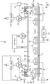
- Appendix 1 for drying metallic workpieces is designed especially for vehicle bodies 3.
- the plant 1 comprises a drying chamber 5 designed as a process chamber. Through the drying tunnel 5, the vehicle bodies 3, which are mounted on skids 7, can be moved by means of a conveying device 9.
- the conveyor has an electric drive 10.
- the dryer tunnel 5 is lined with metal sheet. It has an entrance lock 11 with an opening 12 and an exit lock 13 with an opening 14.
- the dryer tunnel 5 comprises a drying section 15 which lies between the entrance lock 11 and the exit lock 13.
- the drying section 15 is a receiving area for workpieces.
- the drying section 15 is preferably designed such that about fifteen vehicle bodies 3, which are freshly coated with a paint and / or a solvent, can be dried more or less simultaneously at the same time.
- air is circulated for drying by means of a fan 61. In order to keep the air at a constant temperature for drying, while the air is passed through a heater 63.
- a line 65 for exhaust air which feeds air contaminated with solvent from the dryer tunnel 5 to a purification reactor 67.
- a nozzle 17, 19 for generating a fluid flow curtain 21, 23.
- the nozzles 17, 19 are acting via a fan acting as a compressor for fresh air 25, 27 through one above the ceiling 6 of the dryer tunnel 5 arranged chamber 29, 31 supplied with fresh air.
- the nozzles 17, 19 preferably have a narrow slot-shaped opening 33, 35, which extends substantially over the width of the dryer tunnel 5.
- the slot-shaped opening 33, 35 of the nozzles 17, 19 opens into the interior 39 of the dryer tunnel 5.
- the effluent from the nozzles 17, 19 Fluid is guided on a guide plate with a guide contour 211 in the interior of the dryer tunnel.
- a temperature sensor 69, 71st for an advantageously possible detection of the temperature of the interior 39 via the nozzles 17, 19 supplied fluid is located on the guide contour 211, a temperature sensor 69, 71st
- the fluid flow curtain 21, 23 preferably extends in each case at an angle of 40 ° ⁇ a ⁇ 60 ° relative to the horizontal 37. It is directed into the interior 39 of the dryer tunnel 5.
- the fluid flow flowing out of the nozzles 17, 19 expands toward the bottom 41 of the dryer tunnel 5.
- the velocity of the flow of the fluid curtain 21, 23 forming fresh air decreases as gaseous fluid.
- the fluid flow curtain 21, 23 separates the gas atmosphere in the interior 39 of the dryer tunnel 5 from the ambient air 42.
- a solvent sensor 73 is arranged in the drying section 15.
- the gaseous fluid supplied to the nozzles 17, 19 in the form of air is preheated in a heating device 43, 44 to a desired process temperature T soll , which is preferably in a temperature range of 200 ° C. ⁇ T soll ⁇ 250 ° C.
- T soll a desired process temperature
- the fluid flow curtain 21, 23 consists of fresh air, it can be ensured that a lower explosion limit for organic solvents in the drying zone 15 of the dryer tunnel 5 is not exceeded.
- the preheating of the supplied fluid ensures that in the entrance lock 11 and the exit lock 13 of the dryer tunnel 5 no condensate is formed.
- a control device 45, 47 in the system for drying.
- the fluid flow is set as a function of the number of vehicle bodies moved through the drying zone 15 of the dryer tunnel by means of a sensor 49, 51 and due to the signals of the temperature sensors 69, 71 and the solvent sensor 73.
- the fluid flow is adjusted so that during operation Appendix 1, the so-called lower explosion limit of the composition of the gas atmosphere in the dryer tunnel 5 is not exceeded.
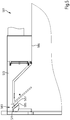
- the Fig. 2 is a sectional view of the entrance lock 11 of the drying plant 1 from Fig. 1 ,
- the nozzle 17 in the entrance lock 11 is a slot nozzle.
- the nozzle 17, the heated fresh air in the heater 44 via a pipe 201 is supplied.
- the pipeline 201 opens into a chamber 203.
- the fresh air is passed via air filter 205 and an obliquely arranged guide plate 207 to the nozzle 17.
- the guide plate 207 in the lock 11 can be pivoted about an axis of rotation 208 in the direction of the arrow 214.
- the pivoting of the baffle 207 opens an access to the filter 205 so that maintenance work can be performed there.
- the nozzle 17 has a slot-shaped opening 209.
- the slot-shaped opening 209 of the nozzle 17 is set back relative to the cover 6 of the dryer tunnel 5. This makes it possible to avoid impairments and damage of a not yet dried coating of vehicle bodies, which are moved through the entrance lock 11 into the dryer tunnel 5, even at high flow velocities of a fluid flow emerging from the nozzle 17. Important for the avoidance of such damage is a comparatively large distance of the opening 209 of the nozzle 17 from the bottom 41 of the dryer tunnel 5. This can be achieved by a recessed arrangement of the nozzle 17 in the drying tunnel 5. This ensures that the momentum of the gaseous fluid flowing out of the nozzle 17 is so much attenuated already in the middle of the dryer tunnel that corresponding coatings of Car body 3 through the fluid flow curtain 21 can not be damaged.
- the fluid flow 210 emerging from the opening 209 of the nozzle 17 is guided into the interior of the dryer tunnel 5 along the contour 211 of a guide plate acting as a guide vane.
- the length L of the contour 211 of the baffle 207 corresponds to 20 to 40 times the slot width B of the nozzle opening 209th
- the end wall 215 there is an end wall 215 on the side of the contour 211 facing the entrance opening 213 of the dryer tunnel 5.
- the end wall 215 extends across the width of the lock 11.
- the end wall 215 defines with the contour 211 and a ridge element 212 a mixing chamber 217 for gaseous fluid 219.
- the mixing chamber 217 is set back relative to the cover 6 of the dryer tunnel 5.
- the mixing chamber 217 is located in the lock 11 above the inlet opening 213.
- the mixing chamber 217 is adjacent to the inlet opening 213.
- the baffle with the contour 211 separates the mixing chamber 217 from a secondary chamber 216.
- the secondary chamber 216 opens into the interior 39 of the dryer tunnel 5.
- the secondary chamber 216 forms a dead space for air from the dryer tunnel 5.
- the on the back of the baffle with the Leitkontur 211 formed secondary chamber causes the fluid flow 210 is guided on the Leitkontur 211 due to the Coanda effect without stall.
- the Fig. 3 is a three-dimensional view of the entrance lock 11 from Fig. 2 ,
- the slot-shaped opening 209 of the nozzle 17 extends over the entire width of the inlet opening 213 of the dryer tunnel 5.
- the slot-shaped opening 209 of the nozzle 17 is so narrow that the fluid flow emerging from the nozzle 17 forms a fluid flow curtain over a wide flow range with different outlet speeds , This fluid flow prevents in particular an entry of dirt particles 301 from the environment in the Fig. 1 shown drying plant 1 in the interior of the dryer tunnel. 5
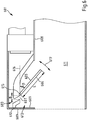
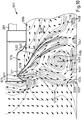
- the Fig. 4 shows with arrows the flow conditions for air in the entrance lock 11 in the plane of a longitudinal section of the dryer tunnel 5 from Fig. 1 ,
- the fresh air supplied to the dryer tunnel 5 via the slit-shaped nozzle 17 causes a fluid flow curtain 401 on the exit side of the nozzle 17.
- the fluid flow curtain 401 extends from fresh air flowing in the direction of the arrows 402 in the form of a curved lobe 403 to the bottom 41 of the entrance lock 11.
- the lobe 403 has the height H of the center of the entrance lock 11 has a thickness D, which is determined by the width B of the opening 209 of the nozzle 17.
- the fresh air flowing out of the nozzle 17 generates a flow roller 407 of air.
- the air flows around a center 409 in a flow direction indicated by the arrows 406.
- the air in the region of the center 409 is substantially stationary.
- the air circulated in the flow roll 407 is at least partially mixed with the fresh air blown through the nozzle 17.
- the flow roll 407 extends from the bottom 41 to the ceiling 6 of the entrance lock 11th
- the mixing chamber 217 defined by the end plate 215 on the side of the baffle 211 facing the input opening 213 and the baffle 211 and the ridge element 212 takes up a small portion of the air circulated in the flow roller 407.
- this air is entrained to a large extent by the flowing from the opening 209 of the nozzle 17 gaseous fluid and added.
- This increases the volume flow of the fluid curtain 401 in the area of the arrows 402.
- the volume flow of the fluid flow curtain 401 can thus consist of 30% or more of gaseous fluid which is supplied to the fluid flow from the nozzle 17 via the mixing chamber 217. This has the consequence that even with a comparatively small amount of fresh air blown in up to the bottom 41 of the dryer tunnel 5 extending fluid flow curtain 401 can be generated.
- the air from the mixing chamber 217 is returned to the flow roll 407 in this way.
- only a small portion of the gaseous fluid supplied via the nozzle 17 into the interior 39 of the dryer tunnel 5 leaves through the opening 213 of the lock 11 of the dryer tunnel 5.
- the gaseous fluid flowing out of the nozzle 17 thus passes for the most part in the direction of the arrows 408 into the interior of the dryer tunnel 5.
- a barrier is formed in the flow roller in the region of the opening 213 of the lock 11 407 circulated air generated. This barrier causes a thermal separation of the interior 39 of the dryer tunnel 5 from the outside area. In addition, this barrier also prevents the entry of dust and dirt particles into the interior 39 of the dryer tunnel 5.
- the Fig. 5 shows a modified embodiment of a lock 501 for a drying plant.
- the lock 501 has a nozzle 503 for supplying fresh air with a compared to the lock 11 from Fig. 1 modified nozzle geometry.
- the nozzle 503 is a dual-chamber nozzle.
- the nozzle 503 has a slot-shaped nozzle opening 505 and a slot-shaped nozzle opening 507, which extends in each case over the entire width of the ceiling 509 of the entrance lock 501.
- the nozzle 503 comprises a pivotable control flap 511.
- the control flap 511 is movable by means of a spindle drive not shown. For moving the control flap but also an adjusting mechanism with shaft or a cable is suitable.
- the fresh air supplied to the nozzle 503 via the chamber 513 can be selectively directed either through the nozzle opening 507, the nozzle opening 509, or through the nozzle openings 507, 509.
- it is by means of the control flap 511 it is possible to vary the air flow from the nozzle 503 according to the position of vehicle bodies in the area of the entrance opening of a dryer tunnel. With this measure it can be achieved that a paint layer applied to a vehicle body is not impaired by the fluid flow formed by the fresh air from the nozzle 503.
- the control valve 511 the thickness D of the fluid flow curtain and thus the amount and / or the speed of the supplied fresh air into the interior of the dryer tunnel can be adjusted.
- a nozzle with a plurality of nozzle openings and with a plurality of control valves can be provided to set a fresh air flow for a dryer tunnel.
- the Fig. 6 shows a portion of an alternative embodiment for a lock 601 with a nozzle 603 to form an air curtain in the entrance or exit area of a drying plant.
- the nozzle 603 in the lock 601 is associated with a guide plate 605 which acts as a guide wing and which is preferably pivotably arranged.
- the baffle optionally has an at least partially curved outer contour. In particular, it extends over the entire width of the nozzle 603.
- the pivotable baffle 605 at the opening 607 of the nozzle 603 is pivotally mounted on the ceiling 608 of the lock 601 at a pivot 615.
- the pivotable guide plate 605 protrudes into the interior 611 of the lock 601.
- the length L of the contour of the guide plate 605 corresponds approximately to 20 to 40 times the slot width B of the nozzle opening.
- the swiveling baffle 605 opposite, in turn, an end wall 609 is disposed in the lock 601.
- the pivotable guide plate 605 and the end wall 609 together with a ridge element 612 also define a mixing chamber 613 here. Due to the pivotability of the guide plate 605, the geometry of the mixing chamber 613 in the lock 601 can
- the guide plate 605 is associated with a not shown actuator.
- By pivoting the baffle 605 corresponding to the double arrow 617 it is possible to set an angle of attack ⁇ with respect to the horizontal 616 and thus the direction of a fluid flow curtain generated in the sluice 601 with gaseous fluid from the nozzle 603.
- By pivoting the contour of the Leitulatel formed by the guide plate 605 is displaced, on which the gaseous fluid flowing from the nozzle 607 is guided.
- the shape of the flow roll can be changed, which is formed on the side of the guide plate 605 facing the opening 619, due to the fluid flowing out of the nozzle 603.
- baffle 605 By the baffle 605 is pivoted to the ceiling 608 of the lock 601, a comparatively shallow flow of gaseous fluid into the lock can be effected.
- the guide plate 605 up and down By moving the guide plate 605 up and down, the flow direction of the fluid flowing out of the nozzle can be adapted to the position and geometry of vehicle bodies, which are moved through the lock 601 into the interior of the dryer tunnel.
- a paint layer applied to vehicle bodies, which is to be dried in the drying tunnel will not be faded and will not be damaged in the drying tunnel.
- the Fig. 7 shows a portion of another alternative embodiment for a lock 701 with a nozzle 703 to form an air curtain in the entrance or exit area of a drying plant.
- the nozzle 703 has a diffuser which adjoins the narrowed cross section of the nozzle and thus widens the flow cross section for the fluid.
- the nozzle 703 with subsequent diffuser thus has a flow channel 704 whose cross-section widens toward the interior 711 of the lock 701.
- the structure of the lock 701 otherwise corresponds to that of the lock 601 Fig. 6 , Corresponding assemblies of the lock 601 and 701 are therefore in Fig. 7 with compared to Fig. 6 indicated by the number 100 increased reference numerals.
- the lock 701 has an end wall 709 with one or more inlet openings for ambient air.
- the end wall 709 openings in the form of a sieve-like perforation. This measure also makes it possible to draw in air from an upper region 721 in the vicinity of the lock 701.
- the air sucked into the lock 701 in this way is preferably mixed with air from a flow roll which forms at the opening of the lock. Subsequently, the sucked air and a part of the air from the flow roll are mixed in the exiting from the diffuser fluid flow.
- the Fig. 8 shows a portion of another alternative embodiment for a lock 801 with an aperture 803 having an opening 804 for forming an air curtain in the entrance or exit area of a drying plant.
- the construction of the lock 801 corresponds to that of the lock 701 Fig. 7 , Corresponding modules of the lock 701 and 801 are therefore in Fig. 8 with compared to Fig. 7 indicated by the number 100 increased reference numerals.
- the end wall 809 of the lock 801 is designed with a recess 816. This measure also makes it possible to take in air from an upper region 821 of the vicinity of the lock 801 into the flow roll generated by the orifice 803 at the opening of the lock.
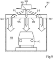
- the Fig. 9 shows a cross section of an entrance or exit lock 901 of a dryer tunnel 900 in a drying plant with a vehicle body 912.
- the lock 901 has slot-shaped nozzles 903, 905, 907, which are located on the ceiling 910 of the lock 901.
- the nozzles 903, 905, 907 can be acted upon by a device for supplying fresh air, not shown, with a fresh air stream 909.
- the lock 901 there are control valves, by means of which the fresh air stream 909 can be divided into different channels 911, 913 and 915 for the separate pressurization of the nozzles 903, 905 and 907 with fresh air.
- This measure makes it possible to adjust a fluid flow curtain 917 at the openings of a dryer tunnel which, corresponding to the passage of workpieces, e.g. Vehicle bodies over the width B of the opening can be set differently.
- the Fig. 10 shows a longitudinal section of another lock 1011 for a dryer tunnel in a plant for drying metallic workpieces.
- the Fig. 4 are here also the flow conditions for air in the lock 1011 indicated by arrows.
- the fresh air supplied to the dryer tunnel via the slot-shaped nozzle 1017 effects a fluid flow curtain 1401 on the outlet side of the nozzle 1017.
- fresh air can be understood to mean in particular precompressed, heated and / or cleaned and / or dried air whose state parameters are optimally adjusted.
- the fluid flow curtain 1401 extends (from fresh air flowing in the direction of the arrows 1402) in the form of a more or less bent lug 1403 in the direction of a bottom 1041 of the lock 1011.
- the fresh air flowing from the nozzle 1017 generates a flow roller 1407 of air.
- the air flows around a center 1409 in a flow direction indicated by the arrows 1406.
- the air in the region of the center 1409 is substantially stationary.
- the air circulated in the flow roll 1407 is at least partially mixed with the fresh air blown through the nozzle 1017.
- the flow roll 1407 extends from the floor 1041 to the ceiling 1006 of the entrance lock 1011.
- the lock 1011 has a guide contour on the side of the inlet opening 1213 which faces the opening 1009 of the nozzle 1017
- the baffle 1211 and the first wall 1215 limit and enclose in sections a downwardly open mixing chamber 1217.
- a flow guiding element 1218 is positioned in the form of a "flow wing", which, like the opening 1009 of the nozzle 1017, preferably extends over the entire width of the lock 1011.
- the baffle 1211 separates the mixing chamber 1217 from a sub-chamber 1216.
- the sub-chamber 1216 acts as a dead space for air in which lower flow velocities are present than in the remainder of the lock (except for the actually negligible center of rotation 1409 of the flow roll).
- a silhouette wall 1220 is arranged in the region of the opening 1213.
- Silhouettenwandung 1220 serves in particular as a flow barrier or as a bottom-side flow guide.
- the silhouette wall 1220 is preferably made of spring steel or other temperature and / or corrosion resistant steels.
- the silhouette wall 1220 can be pivoted about a (horizontal) axis 1222 according to the arrow 1224.
- the mixing chamber 1217 absorbs a small part of the air circulated in the flow roll 1407.
- this air is directed with the flow blade 1218 to the gaseous fluid flowing out of the opening 1209 of the nozzle 17. It is entrained by the gaseous fluid.
- This increases the volume flow of the fluid curtain 1401 in the area of the arrows 1402.
- the volume flow of the fluid flow curtain 1401 may thus to a large extent consist of gaseous fluid which is supplied to the fluid flow from the nozzle 1017 via the mixing chamber 1217.
- a fluid flow curtain 1401 extending to the bottom 1041 of the dryer tunnel can be produced.
- the air from the mixing chamber 1217 is returned to the flow roll 1407 in this way.
- the gaseous fluid flowing out of the nozzle 1017 thus passes for the most part in the direction of the arrows 1408 into the interior of the dryer tunnel.
- a barrier with air circulated in the flow roller 1407 is generated in the region of the opening 1213 of the lock 1011, which thermally separates the interior 1039 of the dryer tunnel from the outside area and, moreover, also an entry of dust and dirt particles into the drying tunnel.
- the silhouette wall 1220 at the bottom 1041 of the lock 1011 causes the flow roll 1407 to be comparatively narrow. Only when a workpiece is moved into the dryer tunnel, the silhouette wall according to the arrow 1220 is briefly folded in the direction of the bottom 1041.
- a process chamber 5 has an interior 39. In the interior 39 there is a receiving area 15 for workpieces 3, wherein the interior 39 has a relation to the environment of the process chamber increased or reduced temperature.
- the process chamber has an at least temporarily open to the environment opening 12, 14 for the supply or removal of workpieces 3.
- the process chamber comprises a device 17, 19, 25, 29, 33, 37, 35 for the injection of gaseous fluid into the interior 39.
- the device for injecting gaseous fluid has at least one nozzle 17, 19 for generating a fluid flow curtain 21, 23 between the opening 12, 14 and the receiving area 15 for workpieces 3.
- the supplied gaseous fluid is conditioned with respect to its physical and / or chemical parameters and has in particular opposite the interior of the process chamber and / or to the environment of the process chamber different temperature.
Landscapes
- Engineering & Computer Science (AREA)
- Mechanical Engineering (AREA)
- General Engineering & Computer Science (AREA)
- Chemical & Material Sciences (AREA)
- Combustion & Propulsion (AREA)
- Drying Of Solid Materials (AREA)
- Powder Metallurgy (AREA)
- Details Or Accessories Of Spraying Plant Or Apparatus (AREA)
- Coating Apparatus (AREA)
- Nozzles (AREA)
- Chemical Vapour Deposition (AREA)
- Furnace Details (AREA)
Claims (13)
- Chambre de traitement (5) comprenant un espace interne (39) qui comprend une région de réception (15) configurée en forme de tunnel pour des pièces (3), présentant un fond (41) et un plafond (6), comprenant une ouverture (12, 14) pour l'alimentation ou l'évacuation de pièces (3), et comprenant un dispositif (17, 19, 25, 29, 33, 35, 35) pour insuffler un fluide gazeux dans l'espace interne (39), qui présente au moins une buse en forme de fente (17, 19) ou un diaphragme (803) pour générer un rideau de courant de fluide (21, 23) entre l'ouverture (12, 14) et la région de réception (15) pour les pièces (3), la buse en forme de fente (17, 19) ou le diaphragme (803) acheminant le fluide gazeux par le biais du plafond (6) de l'espace interne (39) avec une direction d'écoulement (402) oblique par rapport au fond (41) le long d'un contour de guidage (211) dans l'espace interne (39),
caractérisée en ce que
le contour de guidage (211), avec une paroi (215) d'un sas d'entrée (11) ou d'un sas de sortie (13) disposée sur un côté du contour de guidage (211) tourné vers l'ouverture (12, 14), délimite une chambre de mélange (217) disposée en retrait vers le haut par rapport au plafond (6) au-dessus de l'ouverture (12, 14), hors de laquelle de l'air provenant de la région de l'ouverture (12, 14) est entraîné par le fluide gazeux acheminé dans l'espace interne (39) par la buse (17, 19) en forme de fente ou par le diaphragme (803) et est aspiré dans l'espace interne (39). - Chambre de traitement selon la revendication 1,
caractérisée en ce que le contour de guidage (606) est réalisé au niveau d'une ailette de guidage pivotante (605). - Chambre de traitement selon la revendication 1 ou 2, caractérisée en ce que la paroi (709, 809) présente une ou plusieurs ouvertures (816) pour le passage d'air en circulation provenant de la région de l'ouverture (12).
- Chambre de traitement selon l'une quelconque des revendications 1 à 3, caractérisée en ce qu'une chambre auxiliaire (216) agissant en tant qu'espace mort pour du fluide gazeux est réalisée sur un côté du contour de guidage (211) opposé à la chambre de mélange (217).
- Chambre de traitement selon l'une quelconque des revendications 1 à 4, caractérisée en ce qu'une ailette de guidage (1218) est disposée dans la chambre de mélange (1217).
- Chambre de traitement selon l'une quelconque des revendications 1 à 5, caractérisée en ce que l'au moins une buse (503) présente un dispositif (511) pour l'ajustement de la quantité d'écoulement pour du fluide traversant la buse (503) et/ou en ce que plusieurs buses (903, 905, 907) sont pourvues d'un dispositif pour l'ajustement de la quantité d'écoulement pour du fluide traversant la buse, afin d'ajuster différemment le rideau de courant de fluide entre l'ouverture d'entrée et la région de réception de pièces (912) dans différentes portions.
- Chambre de traitement selon l'une quelconque des revendications 1 à 6, caractérisée en ce qu'une barrière à l'écoulement pivotante (1220) est prévue pour commander un écoulement de fluide réalisé dans l'espace interne (1039).
- Chambre de traitement selon l'une quelconque des revendications 1 à 7, caractérisée en ce que le dispositif pour insuffler du fluide gazeux présente un dispositif de chauffage (43, 44) pour chauffer le fluide gazeux.
- Installation de séchage et/ou de durcissement et/ou installation de peinture comprenant une chambre de traitement (5) réalisée selon l'une quelconque des revendications 1 à 8.
- Procédé pour faire fonctionner une chambre de traitement (5) qui présente un espace interne (39) avec une région de réception en forme de tunnel (15) pour des pièces (3), avec un fond (41), avec un plafond (6) et avec une ouverture (12, 14) pour l'alimentation ou l'évacuation de pièces (3), et qui contient un dispositif (17, 19, 25, 29, 33, 37, 35) pour insuffler du fluide gazeux dans l'espace interne (39), dans lequel du fluide gazeux est insufflé à travers au moins une buse en forme de fente (17, 19) ou un diaphragme (803) par le biais du plafond (6), lequel fluide génère un rideau de courant de fluide (21, 23) disposé entre l'ouverture (12, 14) et la région de réception (15) pour les pièces (3), le fluide gazeux étant acheminé dans l'espace interne (39) avec un dispositif d'écoulement (402) opposé à l'ouverture (12, 14), tourné vers le fond (41) et oblique par rapport au fond (41),
caractérisé en ce que
du côté du rideau de courant de fluide (21, 23) tourné vers l'ouverture (12, 14) est généré un rouleau d'écoulement (407) constitué au moins en partie d'air mélangé au fluide insufflé, qui s'étend depuis le fond (41) jusqu'au plafond (6) dans un sas d'entrée ou un sas de sortie (11, 13), un contour de guidage (211) étant fourni et le fluide gazeux insufflé par le biais de l'au moins une buse (17, 19) ou du diaphragme (803) dans l'espace interne (39) étant guidé le long du contour de guidage (211) dans l'espace interne (39) et une paroi (215, 1215) étant fournie du côté du contour de guidage (211, 1211) tourné vers l'ouverture (213, 1213), laquelle délimite une chambre de mélange (217, 1217) avec le contour de guidage (211, 1211), dans laquelle du fluide provenant d'un rouleau d'écoulement (407, 1407) réalisé sur un côté du rideau de fluide (21, 23) tourné vers l'ouverture (12, 14) est mélangé avec l'air provenant de la région d'ouverture (213, 1213) et est aspiré dans l'espace interne (39, 1039) par le fluide gazeux s'écoulant à travers la buse (17, 19, 1017) ou le diaphragme (803). - Procédé selon la revendication 10, caractérisé en ce que le fluide gazeux insufflé par le biais de l'au moins une buse (17, 19) ou du diaphragme (803) dans l'espace interne (39) est guidé au niveau du contour de guidage (211) sans qu'il ne se produise un décrochement de l'écoulement.
- Procédé selon la revendication 10 ou 11, caractérisé en ce que le contour de guidage (606) est pivoté pour ajuster le rideau de courant de fluide (21, 23).
- Procédé selon l'une quelconque des revendications 10 à 12, caractérisé en ce que le rideau de courant de fluide (21, 23) est étranglé ou interrompu entre l'ouverture (12, 14) et la région de réception (15) pour des pièces (3) et/ou en ce que la direction du rideau de courant de fluide (21, 23) est modifiée lorsqu'une pièce (3) est déplacée à travers l'ouverture (12, 14).
Priority Applications (4)
| Application Number | Priority Date | Filing Date | Title |
|---|---|---|---|
| PL11757635T PL2633252T3 (pl) | 2010-10-28 | 2011-09-16 | Komora procesowa z urządzeniem do wdmuchiwania płynu gazowego |
| EP16196596.7A EP3147613B1 (fr) | 2010-10-28 | 2011-09-16 | Chambre de traitement comprenant un dispositif pour insuffler un fluide gazeux |
| EP18155195.3A EP3336468B1 (fr) | 2010-10-28 | 2011-09-16 | Chambre de traitement comprenant un dispositif pour insuffler un fluide gazeux |
| PL18155195T PL3336468T3 (pl) | 2010-10-28 | 2011-09-16 | Komora procesowa z urządzeniem do wdmuchiwania płynu w postaci gazowej |
Applications Claiming Priority (2)
| Application Number | Priority Date | Filing Date | Title |
|---|---|---|---|
| DE102010043087A DE102010043087A1 (de) | 2010-10-28 | 2010-10-28 | Prozesskammer mit Vorrichtung zum Einblasen von gasförmigen Fluid |
| PCT/EP2011/066154 WO2012055634A1 (fr) | 2010-10-28 | 2011-09-16 | Chambre de traitement comprenant un dispositif pour insuffler un fluide gazeux |
Related Child Applications (3)
| Application Number | Title | Priority Date | Filing Date |
|---|---|---|---|
| EP18155195.3A Division EP3336468B1 (fr) | 2010-10-28 | 2011-09-16 | Chambre de traitement comprenant un dispositif pour insuffler un fluide gazeux |
| EP16196596.7A Division EP3147613B1 (fr) | 2010-10-28 | 2011-09-16 | Chambre de traitement comprenant un dispositif pour insuffler un fluide gazeux |
| EP16196596.7A Division-Into EP3147613B1 (fr) | 2010-10-28 | 2011-09-16 | Chambre de traitement comprenant un dispositif pour insuffler un fluide gazeux |
Publications (2)
| Publication Number | Publication Date |
|---|---|
| EP2633252A1 EP2633252A1 (fr) | 2013-09-04 |
| EP2633252B1 true EP2633252B1 (fr) | 2017-01-18 |
Family
ID=44651826
Family Applications (3)
| Application Number | Title | Priority Date | Filing Date |
|---|---|---|---|
| EP16196596.7A Active EP3147613B1 (fr) | 2010-10-28 | 2011-09-16 | Chambre de traitement comprenant un dispositif pour insuffler un fluide gazeux |
| EP11757635.5A Active EP2633252B1 (fr) | 2010-10-28 | 2011-09-16 | Chambre de traitement comprenant un dispositif pour insuffler un fluide gazeux |
| EP18155195.3A Active EP3336468B1 (fr) | 2010-10-28 | 2011-09-16 | Chambre de traitement comprenant un dispositif pour insuffler un fluide gazeux |
Family Applications Before (1)
| Application Number | Title | Priority Date | Filing Date |
|---|---|---|---|
| EP16196596.7A Active EP3147613B1 (fr) | 2010-10-28 | 2011-09-16 | Chambre de traitement comprenant un dispositif pour insuffler un fluide gazeux |
Family Applications After (1)
| Application Number | Title | Priority Date | Filing Date |
|---|---|---|---|
| EP18155195.3A Active EP3336468B1 (fr) | 2010-10-28 | 2011-09-16 | Chambre de traitement comprenant un dispositif pour insuffler un fluide gazeux |
Country Status (18)
| Country | Link |
|---|---|
| US (1) | US9316406B2 (fr) |
| EP (3) | EP3147613B1 (fr) |
| JP (1) | JP5330610B2 (fr) |
| KR (2) | KR102112681B1 (fr) |
| CN (1) | CN103189702B (fr) |
| BR (1) | BR112013010030B1 (fr) |
| CA (1) | CA2813097C (fr) |
| DE (1) | DE102010043087A1 (fr) |
| ES (2) | ES2620241T3 (fr) |
| HU (2) | HUE032908T2 (fr) |
| MX (1) | MX340114B (fr) |
| MY (1) | MY158630A (fr) |
| PL (2) | PL2633252T3 (fr) |
| PT (2) | PT3336468T (fr) |
| RU (1) | RU2589971C2 (fr) |
| TR (1) | TR201900642T4 (fr) |
| WO (1) | WO2012055634A1 (fr) |
| ZA (1) | ZA201303086B (fr) |
Families Citing this family (28)
| Publication number | Priority date | Publication date | Assignee | Title |
|---|---|---|---|---|
| DE102010043087A1 (de) * | 2010-10-28 | 2012-05-03 | Dürr Systems GmbH | Prozesskammer mit Vorrichtung zum Einblasen von gasförmigen Fluid |
| DE102011078707A1 (de) | 2011-07-05 | 2013-01-10 | Dürr Systems GmbH | Fördervorrichtung |
| DE102012003299A1 (de) | 2012-02-18 | 2013-08-22 | Eisenmann Ag | Verfahren zum Behandeln von Gegenständen und Anlage hierfür |
| US9970706B2 (en) | 2012-05-02 | 2018-05-15 | Duerr Systems Ag | System having a process chamber for workpieces |
| DE102012207312A1 (de) * | 2012-05-02 | 2013-11-07 | Dürr Systems GmbH | Prozesskammer mit Vorrichtung zum Einblasen von gasförmigem Fluid |
| US10605529B2 (en) | 2012-05-02 | 2020-03-31 | Duerr Systems Ag | System having a process chamber for workpieces |
| DE102012020357B4 (de) * | 2012-10-16 | 2014-08-14 | Eisenmann Ag | Vorrichtung zum Temperieren von Gegenständen |
| DE102013000754A1 (de) * | 2013-01-17 | 2014-07-31 | Eisenmann Ag | Vorrichtung zum Temperieren von Gegenständen |
| DE102013004136A1 (de) | 2013-03-09 | 2014-09-11 | Volkswagen Aktiengesellschaft | Vorrichtung zum Trocknen eines Werkstücks und Verfahren zum Betrieb einer derartigen Vorrichtung |
| JP6384673B2 (ja) * | 2015-04-08 | 2018-09-05 | パナソニックIpマネジメント株式会社 | 乾燥装置 |
| DE102015214711A1 (de) | 2015-07-31 | 2017-02-02 | Dürr Systems Ag | Behandlungsanlage und Verfahren zum Behandeln von Werkstücken |
| DE102015214706A1 (de) * | 2015-07-31 | 2017-02-02 | Dürr Systems Ag | Behandlungsanlage und Verfahren zum Behandeln von Werkstücken |
| DE102015224916A1 (de) | 2015-12-10 | 2017-06-14 | Dürr Systems Ag | Behandlungsanlage und Verfahren zum Behandeln von Werkstücken |
| JP6791583B2 (ja) * | 2017-01-13 | 2020-11-25 | パーカーエンジニアリング株式会社 | 乾燥炉 |
| JP6912910B2 (ja) | 2017-03-21 | 2021-08-04 | トリニティ工業株式会社 | 乾燥システム |
| JP6681853B2 (ja) | 2017-06-16 | 2020-04-15 | 株式会社大気社 | 塗装乾燥炉 |
| DE102018210433A1 (de) * | 2018-06-26 | 2020-01-02 | Dürr Systems Ag | Trennvorrichtung und Behandlungsanlage |
| DE102018210435A1 (de) | 2018-06-26 | 2020-01-02 | Dürr Systems Ag | Fördersystem, Behandlungsanlage und Förderverfahren |
| DE102019213430A1 (de) * | 2019-09-04 | 2021-03-04 | Dürr Systems Ag | Trennvorrichtung, Behandlungsanlage, Verfahren zum Trennen zweier Raumbereiche und Verfahren zum Behandeln von Werkstücken |
| CN112577304B (zh) * | 2020-12-02 | 2022-05-03 | 浙江驿公里智能科技有限公司 | 一种出风口 |
| DE102020216427A1 (de) | 2020-12-21 | 2022-06-23 | Dürr Systems Ag | Trennvorrichtung, Behandlungsanlage und Verfahren zum Behandeln von Werkstücken |
| CN112555792A (zh) * | 2020-12-24 | 2021-03-26 | 贵州九鼎新能源科技开发有限公司 | 空气能热泵电磁蒸汽烘干设备 |
| DE102021115612A1 (de) * | 2021-06-16 | 2022-12-22 | Ulf Reinhardt | Stiftofen zur Trocknung von Behältereinheiten und Verfahren |
| DE102021118534A1 (de) * | 2021-07-19 | 2023-01-19 | Ulf Reinhardt | Trocknungsvorrichtung und Verfahren zur Trocknung von Lösemittel aufweisenden Behältereinheiten |
| US11619399B1 (en) * | 2021-09-22 | 2023-04-04 | William H. White | Systems and methods for direct use of solar energy |
| CN113941489B (zh) * | 2021-09-22 | 2023-01-17 | 迈赫机器人自动化股份有限公司 | 一种烘干用升降式空气幕装置 |
| DE102022113067A1 (de) | 2022-05-24 | 2023-11-30 | Dürr Systems Ag | Behandlungsanlage und Verfahren zum Behandeln von Werkstücken |
| CN116067132B (zh) * | 2022-12-28 | 2024-03-26 | 昆明理工大学 | 一种玉陶烧制用干燥装置及其干燥方法 |
Family Cites Families (30)
| Publication number | Priority date | Publication date | Assignee | Title |
|---|---|---|---|---|
| US1606442A (en) * | 1923-08-11 | 1926-11-09 | Aaron S Nichols | Paint and varnish drier |
| US2062187A (en) * | 1934-08-25 | 1936-11-24 | Willard L Morrison | Air cooling, circulating, and controlling device and process |
| AT194570B (de) * | 1953-11-03 | 1958-01-10 | Sifrag Spezialappbau & Ingenie | Einrichtung zur Erzeugung eines raumabschließenden Luftvorhanges |
| DE1095497B (de) * | 1954-05-12 | 1960-12-22 | Schilde Maschb Ag | Lufttuer fuer Trockner und Industrieoefen |
| CA654457A (en) * | 1957-06-08 | 1962-12-18 | Rudolf Sterkel | Air curtains |
| FR2257209A5 (fr) * | 1973-11-15 | 1975-08-01 | Air Ind | |
| JPS5397453U (fr) * | 1978-01-13 | 1978-08-08 | ||
| SU807751A1 (ru) * | 1979-05-08 | 1984-04-15 | Черкасский Проектно-Конструкторский Технологический Институт | Сушилка |
| JPS58101756A (ja) * | 1981-12-14 | 1983-06-17 | Toyota Central Res & Dev Lab Inc | 自動車用塗装ブ−ス |
| GB2123936B (en) * | 1982-06-09 | 1985-10-30 | Flakt Limited | Paint curing apparatus |
| SU1479796A1 (ru) * | 1987-05-04 | 1989-05-15 | Трест "Братскстройреконструкция" | Рециркул ционна воздушна завеса |
| SU1612192A2 (ru) * | 1988-12-14 | 1990-12-07 | Проектный Институт Научно-Производственного Объединения "Спектр" | Сушилка |
| US4984740A (en) * | 1989-06-19 | 1991-01-15 | Hodge Robert B | Water sprinkler with variable stream-distance adjustment |
| US5169414A (en) | 1990-07-03 | 1992-12-08 | Flakt, Inc. | Rotary adsorption assembly |
| DE4317768A1 (de) | 1993-05-28 | 1994-12-01 | Somos Gmbh | Verfahren und Vorrichtung zum Aufbereiten eines insbesondere feuchten Adsortionsmittels |
| JP3071098B2 (ja) * | 1994-06-18 | 2000-07-31 | 株式会社東洋製作所 | 連続急速凍結装置 |
| CN2204395Y (zh) * | 1994-09-15 | 1995-08-02 | 旭清工业股份有限公司 | 热风输送机的风屏装置 |
| DE59608068D1 (de) | 1996-05-03 | 2001-12-06 | Graeff Roderich Wilhelm | Verfahren und Vorrichtung zum Aufbereiten eines Adsorptionsmittels |
| PT1242779E (pt) * | 1999-04-21 | 2005-08-31 | Junair Group Ltd | Sistema de secagem de pintura |
| JP3907605B2 (ja) * | 2002-10-03 | 2007-04-18 | 株式会社ホソカワ粉体技術研究所 | 造粒装置およびこの造粒装置を用いた粉末製造方法 |
| DE10313113A1 (de) * | 2003-03-24 | 2004-10-14 | Lwt Luftwandtechnologie Gmbh | Luftwand mit doppeltem Luftstrom |
| DE102004025525B3 (de) * | 2004-05-25 | 2005-12-08 | Eisenmann Maschinenbau Gmbh & Co. Kg | Verfahren und Vorrichtung zum Trocknen von Gegenständen, insbesondere von lackierten Fahrzeugkarosserien |
| JP4471883B2 (ja) * | 2005-04-12 | 2010-06-02 | 株式会社東洋製作所 | 二重壁式連続冷却システム |
| AT505391B1 (de) | 2007-10-02 | 2009-01-15 | Wittmann Kunststoffgeraete Gmb | Verfahren und einrichtung zum trocknen von schüttgut |
| JP4493688B2 (ja) * | 2007-11-08 | 2010-06-30 | 株式会社東洋製作所 | 連続急速冷却凍結装置 |
| US8813765B2 (en) * | 2008-05-01 | 2014-08-26 | Petit Auto Wash, Inc. | Vehicle wash systems and methods |
| CN201322517Y (zh) * | 2008-12-15 | 2009-10-07 | 苏州工业园区热处理设备厂有限公司 | 热处理设备的热风烘干炉 |
| DE102009021004B4 (de) * | 2009-04-24 | 2026-04-02 | Dürr Systems Ag | Trocknungs- und/oder Härtungsanlage |
| DE102010024840B4 (de) * | 2010-06-23 | 2016-09-22 | Eisenmann Se | Trockner |
| DE102010043087A1 (de) * | 2010-10-28 | 2012-05-03 | Dürr Systems GmbH | Prozesskammer mit Vorrichtung zum Einblasen von gasförmigen Fluid |
-
2010
- 2010-10-28 DE DE102010043087A patent/DE102010043087A1/de not_active Ceased
-
2011
- 2011-09-16 CA CA2813097A patent/CA2813097C/fr active Active
- 2011-09-16 MY MYPI2013001092A patent/MY158630A/en unknown
- 2011-09-16 EP EP16196596.7A patent/EP3147613B1/fr active Active
- 2011-09-16 RU RU2013124079/06A patent/RU2589971C2/ru active
- 2011-09-16 PL PL11757635T patent/PL2633252T3/pl unknown
- 2011-09-16 HU HUE11757635A patent/HUE032908T2/hu unknown
- 2011-09-16 WO PCT/EP2011/066154 patent/WO2012055634A1/fr not_active Ceased
- 2011-09-16 ES ES11757635.5T patent/ES2620241T3/es active Active
- 2011-09-16 PL PL18155195T patent/PL3336468T3/pl unknown
- 2011-09-16 BR BR112013010030-3A patent/BR112013010030B1/pt active IP Right Grant
- 2011-09-16 PT PT18155195T patent/PT3336468T/pt unknown
- 2011-09-16 HU HUE18155195A patent/HUE041247T2/hu unknown
- 2011-09-16 ES ES18155195T patent/ES2709378T3/es active Active
- 2011-09-16 EP EP11757635.5A patent/EP2633252B1/fr active Active
- 2011-09-16 CN CN201180052489.1A patent/CN103189702B/zh active Active
- 2011-09-16 KR KR1020187031133A patent/KR102112681B1/ko active Active
- 2011-09-16 MX MX2013004743A patent/MX340114B/es active IP Right Grant
- 2011-09-16 EP EP18155195.3A patent/EP3336468B1/fr active Active
- 2011-09-16 TR TR2019/00642T patent/TR201900642T4/tr unknown
- 2011-09-16 KR KR1020137010333A patent/KR101964174B1/ko active Active
- 2011-09-16 PT PT117576355T patent/PT2633252T/pt unknown
- 2011-09-16 JP JP2012552433A patent/JP5330610B2/ja active Active
-
2013
- 2013-04-26 ZA ZA2013/03086A patent/ZA201303086B/en unknown
- 2013-04-29 US US13/872,880 patent/US9316406B2/en active Active
Non-Patent Citations (1)
| Title |
|---|
| None * |
Also Published As
Similar Documents
| Publication | Publication Date | Title |
|---|---|---|
| EP3147613B1 (fr) | Chambre de traitement comprenant un dispositif pour insuffler un fluide gazeux | |
| EP2844937B1 (fr) | Dispositif pourvu d'une chambre de traitement pour pièces d'oeuvre | |
| EP2026910B1 (fr) | Dispositif de peinture | |
| EP2422153B1 (fr) | Dispositif de séchage et/ou de durcissage | |
| DE102010024840B4 (de) | Trockner | |
| DE69301001T3 (de) | Lackierkabine und Verfahren zur Beschleunigung der Verdampfung des Verdünners aus einer Beschichtung auf einer Plattenoberfläche | |
| EP2409778B1 (fr) | Dispositif de revêtement pour pièces usinées allongées | |
| EP3712090A1 (fr) | Installation de traitement et procédé de traitement des pièces | |
| DE2614663B2 (de) | Vorrichtung zur Behandlung eines Werkstückes mit ultraviolettem Licht | |
| WO2021063443A1 (fr) | Système de traitement et procédé de traitement | |
| EP2814619B1 (fr) | Procédé de traitement d'objets et installation correspondante | |
| DE3640699C2 (fr) | ||
| DE202020103567U1 (de) | Behandlungsanlage | |
| EP1342959A1 (fr) | Dispositif pour protéger une ouverture dans une installation de traitement de déchets | |
| WO2019052947A1 (fr) | Installation et procédé de revêtement d'objets | |
| EP2923773A1 (fr) | Système d'évacuation de brouillard de peinture lors de la mise en peinture d'un composant et fuselage d'avion et procédé d'évacuation de brouillard de peinture | |
| EP4264154A1 (fr) | Dispositif de séparation, installation de traitement et procédé de traitement de pièces | |
| WO2021043373A1 (fr) | Dispositif de séparation, installation de traitement, procédé de séparation de deux zones d'un espace et procédé de traitement de pièces | |
| EP2098303B1 (fr) | Installation de revêtement destinée au revêtement d'une pièce à usiner | |
| DE10257320B4 (de) | Kanalsystem für das thermische Behandeln von beschichteten Warenbahnen | |
| AT528072B1 (de) | Lackier- und Trockenkabine und Verfahren zu deren Betrieb | |
| DE1802306A1 (de) | Anlage zum Abschrecken von langgestrecktem Gluehgut,vorzugsweise von Blechen | |
| DE10325471A1 (de) | Verfahren zur Absaugung von schadstoffbelasteter Luft aus einem Arbeitsfeld und Absaugeinrichtung zur Durchführung des Verfahrens, insbesondere für eine Zerkleinerungseinrichtung | |
| DE102006061862A1 (de) | Verfahren und Vorrichtung zum Aufbringen eines Behandlungsmittels aus einer Kammer auf eine Oberfläche |
Legal Events
| Date | Code | Title | Description |
|---|---|---|---|
| PUAI | Public reference made under article 153(3) epc to a published international application that has entered the european phase |
Free format text: ORIGINAL CODE: 0009012 |
|
| 17P | Request for examination filed |
Effective date: 20130423 |
|
| AK | Designated contracting states |
Kind code of ref document: A1 Designated state(s): AL AT BE BG CH CY CZ DE DK EE ES FI FR GB GR HR HU IE IS IT LI LT LU LV MC MK MT NL NO PL PT RO RS SE SI SK SM TR |
|
| DAX | Request for extension of the european patent (deleted) | ||
| 17Q | First examination report despatched |
Effective date: 20140623 |
|
| RIN1 | Information on inventor provided before grant (corrected) |
Inventor name: WIELAND, DIETMAR Inventor name: WINKLER, MARIUS Inventor name: IGLAUER, OLIVER Inventor name: KNUESEL, CHRISTOF |
|
| GRAP | Despatch of communication of intention to grant a patent |
Free format text: ORIGINAL CODE: EPIDOSNIGR1 |
|
| RIC1 | Information provided on ipc code assigned before grant |
Ipc: F26B 21/04 20060101ALI20160111BHEP Ipc: F26B 21/14 20060101ALN20160111BHEP Ipc: F26B 23/02 20060101ALN20160111BHEP Ipc: F26B 15/14 20060101AFI20160111BHEP Ipc: F26B 25/00 20060101ALI20160111BHEP |
|
| INTG | Intention to grant announced |
Effective date: 20160204 |
|
| GRAS | Grant fee paid |
Free format text: ORIGINAL CODE: EPIDOSNIGR3 |
|
| GRAP | Despatch of communication of intention to grant a patent |
Free format text: ORIGINAL CODE: EPIDOSNIGR1 |
|
| RIC1 | Information provided on ipc code assigned before grant |
Ipc: F26B 25/00 20060101ALI20160609BHEP Ipc: F26B 21/04 20060101ALI20160609BHEP Ipc: F26B 15/14 20060101AFI20160609BHEP Ipc: F26B 21/14 20060101ALN20160609BHEP Ipc: F26B 23/02 20060101ALN20160609BHEP |
|
| INTG | Intention to grant announced |
Effective date: 20160704 |
|
| GRAJ | Information related to disapproval of communication of intention to grant by the applicant or resumption of examination proceedings by the epo deleted |
Free format text: ORIGINAL CODE: EPIDOSDIGR1 |
|
| GRAL | Information related to payment of fee for publishing/printing deleted |
Free format text: ORIGINAL CODE: EPIDOSDIGR3 |
|
| GRAP | Despatch of communication of intention to grant a patent |
Free format text: ORIGINAL CODE: EPIDOSNIGR1 |
|
| INTC | Intention to grant announced (deleted) | ||
| RAP1 | Party data changed (applicant data changed or rights of an application transferred) |
Owner name: DUERR SYSTEMS AG |
|
| GRAA | (expected) grant |
Free format text: ORIGINAL CODE: 0009210 |
|
| INTG | Intention to grant announced |
Effective date: 20161123 |
|
| RIC1 | Information provided on ipc code assigned before grant |
Ipc: F26B 21/14 20060101ALN20161111BHEP Ipc: F26B 23/02 20060101ALN20161111BHEP Ipc: F26B 21/04 20060101ALI20161111BHEP Ipc: F26B 15/14 20060101AFI20161111BHEP Ipc: F26B 25/00 20060101ALI20161111BHEP |
|
| AK | Designated contracting states |
Kind code of ref document: B1 Designated state(s): AL AT BE BG CH CY CZ DE DK EE ES FI FR GB GR HR HU IE IS IT LI LT LU LV MC MK MT NL NO PL PT RO RS SE SI SK SM TR |
|
| REG | Reference to a national code |
Ref country code: GB Ref legal event code: FG4D Free format text: NOT ENGLISH |
|
| REG | Reference to a national code |
Ref country code: CH Ref legal event code: EP |
|
| REG | Reference to a national code |
Ref country code: AT Ref legal event code: REF Ref document number: 863153 Country of ref document: AT Kind code of ref document: T Effective date: 20170215 Ref country code: NL Ref legal event code: FP |
|
| REG | Reference to a national code |
Ref country code: IE Ref legal event code: FG4D Free format text: LANGUAGE OF EP DOCUMENT: GERMAN Ref country code: PT Ref legal event code: SC4A Ref document number: 2633252 Country of ref document: PT Date of ref document: 20170222 Kind code of ref document: T Free format text: AVAILABILITY OF NATIONAL TRANSLATION Effective date: 20170215 |
|
| REG | Reference to a national code |
Ref country code: SE Ref legal event code: TRGR |
|
| REG | Reference to a national code |
Ref country code: DE Ref legal event code: R096 Ref document number: 502011011560 Country of ref document: DE |
|
| REG | Reference to a national code |
Ref country code: RO Ref legal event code: EPE |
|
| REG | Reference to a national code |
Ref country code: LT Ref legal event code: MG4D |
|
| REG | Reference to a national code |
Ref country code: ES Ref legal event code: FG2A Ref document number: 2620241 Country of ref document: ES Kind code of ref document: T3 Effective date: 20170628 |
|
| PG25 | Lapsed in a contracting state [announced via postgrant information from national office to epo] |
Ref country code: IS Free format text: LAPSE BECAUSE OF FAILURE TO SUBMIT A TRANSLATION OF THE DESCRIPTION OR TO PAY THE FEE WITHIN THE PRESCRIBED TIME-LIMIT Effective date: 20170518 Ref country code: GR Free format text: LAPSE BECAUSE OF FAILURE TO SUBMIT A TRANSLATION OF THE DESCRIPTION OR TO PAY THE FEE WITHIN THE PRESCRIBED TIME-LIMIT Effective date: 20170419 Ref country code: HR Free format text: LAPSE BECAUSE OF FAILURE TO SUBMIT A TRANSLATION OF THE DESCRIPTION OR TO PAY THE FEE WITHIN THE PRESCRIBED TIME-LIMIT Effective date: 20170118 Ref country code: LT Free format text: LAPSE BECAUSE OF FAILURE TO SUBMIT A TRANSLATION OF THE DESCRIPTION OR TO PAY THE FEE WITHIN THE PRESCRIBED TIME-LIMIT Effective date: 20170118 Ref country code: NO Free format text: LAPSE BECAUSE OF FAILURE TO SUBMIT A TRANSLATION OF THE DESCRIPTION OR TO PAY THE FEE WITHIN THE PRESCRIBED TIME-LIMIT Effective date: 20170418 |
|
| PG25 | Lapsed in a contracting state [announced via postgrant information from national office to epo] |
Ref country code: LV Free format text: LAPSE BECAUSE OF FAILURE TO SUBMIT A TRANSLATION OF THE DESCRIPTION OR TO PAY THE FEE WITHIN THE PRESCRIBED TIME-LIMIT Effective date: 20170118 Ref country code: RS Free format text: LAPSE BECAUSE OF FAILURE TO SUBMIT A TRANSLATION OF THE DESCRIPTION OR TO PAY THE FEE WITHIN THE PRESCRIBED TIME-LIMIT Effective date: 20170118 Ref country code: BG Free format text: LAPSE BECAUSE OF FAILURE TO SUBMIT A TRANSLATION OF THE DESCRIPTION OR TO PAY THE FEE WITHIN THE PRESCRIBED TIME-LIMIT Effective date: 20170418 |
|
| REG | Reference to a national code |
Ref country code: SK Ref legal event code: T3 Ref document number: E 23814 Country of ref document: SK |
|
| REG | Reference to a national code |
Ref country code: FR Ref legal event code: PLFP Year of fee payment: 7 |
|
| REG | Reference to a national code |
Ref country code: DE Ref legal event code: R097 Ref document number: 502011011560 Country of ref document: DE |
|
| PG25 | Lapsed in a contracting state [announced via postgrant information from national office to epo] |
Ref country code: EE Free format text: LAPSE BECAUSE OF FAILURE TO SUBMIT A TRANSLATION OF THE DESCRIPTION OR TO PAY THE FEE WITHIN THE PRESCRIBED TIME-LIMIT Effective date: 20170118 |
|
| PLBE | No opposition filed within time limit |
Free format text: ORIGINAL CODE: 0009261 |
|
| STAA | Information on the status of an ep patent application or granted ep patent |
Free format text: STATUS: NO OPPOSITION FILED WITHIN TIME LIMIT |
|
| REG | Reference to a national code |
Ref country code: HU Ref legal event code: AG4A Ref document number: E032908 Country of ref document: HU |
|
| PG25 | Lapsed in a contracting state [announced via postgrant information from national office to epo] |
Ref country code: SM Free format text: LAPSE BECAUSE OF FAILURE TO SUBMIT A TRANSLATION OF THE DESCRIPTION OR TO PAY THE FEE WITHIN THE PRESCRIBED TIME-LIMIT Effective date: 20170118 Ref country code: DK Free format text: LAPSE BECAUSE OF FAILURE TO SUBMIT A TRANSLATION OF THE DESCRIPTION OR TO PAY THE FEE WITHIN THE PRESCRIBED TIME-LIMIT Effective date: 20170118 |
|
| 26N | No opposition filed |
Effective date: 20171019 |
|
| PG25 | Lapsed in a contracting state [announced via postgrant information from national office to epo] |
Ref country code: SI Free format text: LAPSE BECAUSE OF FAILURE TO SUBMIT A TRANSLATION OF THE DESCRIPTION OR TO PAY THE FEE WITHIN THE PRESCRIBED TIME-LIMIT Effective date: 20170118 |
|
| REG | Reference to a national code |
Ref country code: HU Ref legal event code: HC9C |
|
| REG | Reference to a national code |
Ref country code: CH Ref legal event code: PL |
|
| PG25 | Lapsed in a contracting state [announced via postgrant information from national office to epo] |
Ref country code: MC Free format text: LAPSE BECAUSE OF FAILURE TO SUBMIT A TRANSLATION OF THE DESCRIPTION OR TO PAY THE FEE WITHIN THE PRESCRIBED TIME-LIMIT Effective date: 20170118 |
|
| REG | Reference to a national code |
Ref country code: IE Ref legal event code: MM4A |
|
| REG | Reference to a national code |
Ref country code: BE Ref legal event code: MM Effective date: 20170930 |
|
| PG25 | Lapsed in a contracting state [announced via postgrant information from national office to epo] |
Ref country code: LU Free format text: LAPSE BECAUSE OF NON-PAYMENT OF DUE FEES Effective date: 20170916 |
|
| PG25 | Lapsed in a contracting state [announced via postgrant information from national office to epo] |
Ref country code: CH Free format text: LAPSE BECAUSE OF NON-PAYMENT OF DUE FEES Effective date: 20170930 Ref country code: IE Free format text: LAPSE BECAUSE OF NON-PAYMENT OF DUE FEES Effective date: 20170916 Ref country code: LI Free format text: LAPSE BECAUSE OF NON-PAYMENT OF DUE FEES Effective date: 20170930 |
|
| PG25 | Lapsed in a contracting state [announced via postgrant information from national office to epo] |
Ref country code: BE Free format text: LAPSE BECAUSE OF NON-PAYMENT OF DUE FEES Effective date: 20170930 |
|
| REG | Reference to a national code |
Ref country code: FR Ref legal event code: PLFP Year of fee payment: 8 |
|
| PG25 | Lapsed in a contracting state [announced via postgrant information from national office to epo] |
Ref country code: MT Free format text: LAPSE BECAUSE OF FAILURE TO SUBMIT A TRANSLATION OF THE DESCRIPTION OR TO PAY THE FEE WITHIN THE PRESCRIBED TIME-LIMIT Effective date: 20170118 |
|
| PG25 | Lapsed in a contracting state [announced via postgrant information from national office to epo] |
Ref country code: CY Free format text: LAPSE BECAUSE OF NON-PAYMENT OF DUE FEES Effective date: 20170118 |
|
| PG25 | Lapsed in a contracting state [announced via postgrant information from national office to epo] |
Ref country code: MK Free format text: LAPSE BECAUSE OF FAILURE TO SUBMIT A TRANSLATION OF THE DESCRIPTION OR TO PAY THE FEE WITHIN THE PRESCRIBED TIME-LIMIT Effective date: 20170118 |
|
| PG25 | Lapsed in a contracting state [announced via postgrant information from national office to epo] |
Ref country code: AL Free format text: LAPSE BECAUSE OF FAILURE TO SUBMIT A TRANSLATION OF THE DESCRIPTION OR TO PAY THE FEE WITHIN THE PRESCRIBED TIME-LIMIT Effective date: 20170118 |
|
| PGFP | Annual fee paid to national office [announced via postgrant information from national office to epo] |
Ref country code: FI Payment date: 20210921 Year of fee payment: 11 |
|
| PGFP | Annual fee paid to national office [announced via postgrant information from national office to epo] |
Ref country code: GB Payment date: 20210920 Year of fee payment: 11 Ref country code: TR Payment date: 20210913 Year of fee payment: 11 Ref country code: RO Payment date: 20210903 Year of fee payment: 11 |
|
| PGFP | Annual fee paid to national office [announced via postgrant information from national office to epo] |
Ref country code: PT Payment date: 20210902 Year of fee payment: 11 |
|
| PG25 | Lapsed in a contracting state [announced via postgrant information from national office to epo] |
Ref country code: RO Free format text: LAPSE BECAUSE OF NON-PAYMENT OF DUE FEES Effective date: 20220916 Ref country code: PT Free format text: LAPSE BECAUSE OF NON-PAYMENT OF DUE FEES Effective date: 20230316 Ref country code: FI Free format text: LAPSE BECAUSE OF NON-PAYMENT OF DUE FEES Effective date: 20220916 |
|
| GBPC | Gb: european patent ceased through non-payment of renewal fee |
Effective date: 20220916 |
|
| P01 | Opt-out of the competence of the unified patent court (upc) registered |
Effective date: 20230628 |
|
| PG25 | Lapsed in a contracting state [announced via postgrant information from national office to epo] |
Ref country code: GB Free format text: LAPSE BECAUSE OF NON-PAYMENT OF DUE FEES Effective date: 20220916 |
|
| PG25 | Lapsed in a contracting state [announced via postgrant information from national office to epo] |
Ref country code: TR Free format text: LAPSE BECAUSE OF NON-PAYMENT OF DUE FEES Effective date: 20220916 |
|
| PGFP | Annual fee paid to national office [announced via postgrant information from national office to epo] |
Ref country code: DE Payment date: 20250919 Year of fee payment: 15 |
|
| PGFP | Annual fee paid to national office [announced via postgrant information from national office to epo] |
Ref country code: PL Payment date: 20250904 Year of fee payment: 15 Ref country code: NL Payment date: 20250918 Year of fee payment: 15 Ref country code: IT Payment date: 20250919 Year of fee payment: 15 |
|
| PGFP | Annual fee paid to national office [announced via postgrant information from national office to epo] |
Ref country code: HU Payment date: 20250922 Year of fee payment: 15 |
|
| PGFP | Annual fee paid to national office [announced via postgrant information from national office to epo] |
Ref country code: FR Payment date: 20250922 Year of fee payment: 15 Ref country code: AT Payment date: 20250919 Year of fee payment: 15 |
|
| PGFP | Annual fee paid to national office [announced via postgrant information from national office to epo] |
Ref country code: SE Payment date: 20250918 Year of fee payment: 15 |
|
| PGFP | Annual fee paid to national office [announced via postgrant information from national office to epo] |
Ref country code: CZ Payment date: 20250908 Year of fee payment: 15 |
|
| PGFP | Annual fee paid to national office [announced via postgrant information from national office to epo] |
Ref country code: SK Payment date: 20250909 Year of fee payment: 15 |
|
| PGFP | Annual fee paid to national office [announced via postgrant information from national office to epo] |
Ref country code: ES Payment date: 20251028 Year of fee payment: 15 |