EP2633604B1 - Ensemble pour la fabrication de moteurs électriques différents d'une série de moteurs électriques et procédé de fabrication - Google Patents
Ensemble pour la fabrication de moteurs électriques différents d'une série de moteurs électriques et procédé de fabrication Download PDFInfo
- Publication number
- EP2633604B1 EP2633604B1 EP11764103.5A EP11764103A EP2633604B1 EP 2633604 B1 EP2633604 B1 EP 2633604B1 EP 11764103 A EP11764103 A EP 11764103A EP 2633604 B1 EP2633604 B1 EP 2633604B1
- Authority
- EP
- European Patent Office
- Prior art keywords
- brake
- motor
- end shield
- housing
- screw
- Prior art date
- Legal status (The legal status is an assumption and is not a legal conclusion. Google has not performed a legal analysis and makes no representation as to the accuracy of the status listed.)
- Active
Links
Images




Classifications
-
- H—ELECTRICITY
- H02—GENERATION; CONVERSION OR DISTRIBUTION OF ELECTRIC POWER
- H02K—DYNAMO-ELECTRIC MACHINES
- H02K7/00—Arrangements for handling mechanical energy structurally associated with dynamo-electric machines, e.g. structural association with mechanical driving motors or auxiliary dynamo-electric machines
- H02K7/10—Structural association with clutches, brakes, gears, pulleys or mechanical starters
- H02K7/102—Structural association with clutches, brakes, gears, pulleys or mechanical starters with friction brakes
- H02K7/1021—Magnetically influenced friction brakes
- H02K7/1023—Magnetically influenced friction brakes using electromagnets
- H02K7/1025—Magnetically influenced friction brakes using electromagnets using axial electromagnets with generally annular air gap
-
- F—MECHANICAL ENGINEERING; LIGHTING; HEATING; WEAPONS; BLASTING
- F16—ENGINEERING ELEMENTS AND UNITS; GENERAL MEASURES FOR PRODUCING AND MAINTAINING EFFECTIVE FUNCTIONING OF MACHINES OR INSTALLATIONS; THERMAL INSULATION IN GENERAL
- F16D—COUPLINGS FOR TRANSMITTING ROTATION; CLUTCHES; BRAKES
- F16D55/00—Brakes with substantially-radial braking surfaces pressed together in axial direction, e.g. disc brakes
- F16D55/24—Brakes with substantially-radial braking surfaces pressed together in axial direction, e.g. disc brakes with a plurality of axially-movable discs, lamellae, or pads, pressed from one side towards an axially-located member
- F16D55/26—Brakes with substantially-radial braking surfaces pressed together in axial direction, e.g. disc brakes with a plurality of axially-movable discs, lamellae, or pads, pressed from one side towards an axially-located member without self-tightening action
- F16D55/28—Brakes with only one rotating disc
-
- F—MECHANICAL ENGINEERING; LIGHTING; HEATING; WEAPONS; BLASTING
- F16—ENGINEERING ELEMENTS AND UNITS; GENERAL MEASURES FOR PRODUCING AND MAINTAINING EFFECTIVE FUNCTIONING OF MACHINES OR INSTALLATIONS; THERMAL INSULATION IN GENERAL
- F16D—COUPLINGS FOR TRANSMITTING ROTATION; CLUTCHES; BRAKES
- F16D2121/00—Type of actuator operation force
- F16D2121/18—Electric or magnetic
- F16D2121/20—Electric or magnetic using electromagnets
- F16D2121/22—Electric or magnetic using electromagnets for releasing a normally applied brake
Definitions
- the invention relates to a kit for producing different electric motors of a series of electric motors and to a method for the production.
- the invention is therefore the object of developing the production of engines cost, in particular increasing security.
- the object is achieved in the kit according to claim 1 and in the method according to the features indicated in claim 12.
- a first motor is an asynchronous motor and a second motor is a synchronous motor.
- the first brake can then be installed in the respective B-side end shield so that the same first brake can be received by different motors.
- the first brake is functionally verifiable due to its pre-completed design, even before installation in the respective engine.
- the first or second attachment unit comprises at least a second brake, wherein the second brake is attachable to the housing of the engine.
- the second brake can be attached to the first or second end shield.
- the bearing plate can also serve as a braking surface for the second brake or at least the heat of a friction plate of the second Bring brake to the environment.
- the first brake in the housing of the first or second motor can be arranged.
- the respective motor has a built-in brake and thus is designed as a brake motor, the first brake is identical and thus used multiple times in the series.
- the first motor differs from the second motor, in particular in that the first motor is an asynchronous motor and the second motor is a synchronous motor.
- the series includes different types of engines and despite the different torques similar brakes are used.
- first and second brakes are precompleted, in particular so the brakes are functionally verifiable before assembling the entire engine with brakes.
- the advantage here is that the quality is improved by the function is checked.
- the first brake in a substantially cup-shaped recess of the respective bearing plate is receivable and schraubverbindbar, in particular wherein the respective bearing plate acts as a braking surface for a lining carrier of the second brake, wherein the lining carrier is acted upon by an axially displaceable by means of spring elements anchor plate.
- the advantage here is that the first brake is protected in the end shield.
- the first or second end shield acts as a coil core of the coil winding of the electromagnet of the first brake, wherein the first brake is designed as an electromagnetically actuated spring pressure brake.
- the first and second housing part receives a bearing of the rotor shaft of the motor, in particular wherein the first and second housing part are designed in two pieces and for this purpose comprise at least one further bearing plate which receives the bearing of the rotor shaft of the motor.
- one of the brakes or both brakes is designed as an electromagnetically actuable spring pressure brake, in particular wherein on the bobbin of the electromagnet spring elements are supported, which press on non-energization of the electromagnet an armature disc on a lining carrier, which is thus pressed onto a friction disc, said the armature disk is arranged rotationally fixed relative to the friction disk and to the electromagnet and is arranged so as to be axially displaceable, wherein the lining carrier is connected in a rotationally fixed and axially displaceable manner to the rotor shaft of the electric motor.
- a brake in particular the first and second brake, vorkomplettiert formed, in particular by a friction disc axially spaced by means of a guide member to a coil core of the brake and is set, in particular wherein the guide part is provided for the axial guidance of an armature disk of the brake, wherein the armature disk is limited in the circumferential direction in a form-fitting manner and / or held by the guide part.
- the guide part has a first axial section for guiding the armature disk and a second axial section, which has an external thread for screwing into a threaded bore of the coil core.
- a hexagon socket is provided at an axial end region of the guide part, in particular so that the guide part can be screwed by means of a hexagonal tool in a threaded bore of the spool core.
- the guide member has a recess with internal thread, so that a friction disc of the brake is screw-connected to the guide member by means of a screw, in particular against a shoulder on the outer periphery of the guide member can be fixed.
- the advantage here is that a distance can be specified and maintained.
- a sealing disc is arranged between a space region which comprises the first brake and a space region which comprises the stator, in particular has a seal towards the rotor shaft, such as a labyrinth seal.
- the advantage here is that a high variance in the series achieved by a small number of parts, increases safety and manufacturing is easy.
- a first attachment unit is connected to the first bearing plate, in particular screw-connected and the second bearing plate, a second attachment unit is connected, in particular screw-connected.
- the first and / or second attachment unit comprises at least a second brake, wherein the second brake is mounted on the first or second end shield, in particular wherein the first and second attachment unit are different.
- the brake is precompleted and thus functionally verifiable as a component.
- the guide member for guiding the armature disc is usable as the part holding the pre-completed brake together. So there is no additional part necessary.
- the guide member has at its one axial end a connecting portion, for example external thread, for connection to the bobbin and at its other axial end portion a connecting portion, for example internal thread, for connection to the friction disc.
- the armature disk is limited in the circumferential direction positively and / or held by the guide member.
- the advantage here is that the guide member not only causes the spacing and the cohesion of the friction disc and bobbin but also in the gap space thus created between the friction disc and coil core, the armature disc is providable, although it is arranged linearly movable, but not rotatable in the circumferential direction, because it is positively held.
- the guide part has a first axial section for the axial guidance of the armature disk, that is to say in particular a cylindrical surface section is provided in this first axial section. and has a second axial portion having an external thread for screwing into a threaded bore of the spool core.
- a hexagon socket is provided at an axial end region of the guide part, in particular so that the guide part can be screwed by means of a hexagonal tool in a threaded bore of the spool core.
- the friction disc is employed by means of a screw connection, in particular with a screw, against a step of the guide part, wherein the friction plate and the guide part are screw-connected by means of the screw connection.
- the guide member is screwed into the bobbin to a concern of another trained on the guide part heel.
- the advantage here is that the distance can be specified in a simple manner.
- the guide member has a recess with internal thread, so that the friction disc of the brake is screw-connected to the guide member by means of a screw, in particular against a shoulder on the outer periphery of the guide member can be fixed.
- the advantage here is that simple connection means are used.
- the coil core of the brake for receiving a bearing of a rotor shaft is formed, in particular where the from the bearing and of the Coil winding of the brake overlapped axial areas overlap or equal.
- the advantage here is that the coil core not only passes through magnetic fields but even derived from the bearing forces, as in a torque arm derived.
- the material is designed according fixed and still selected ferromagnetic.
- the brake is in a housing part, in particular bearing plate, receivable, in particular in a substantially cup-shaped recess of this housing part can be received and screw-connected.
- the advantage here is that the brake is protectable in a simple and robust manner.
- the brake is designed as an electromagnetically actuated spring pressure brake, in particular wherein on the bobbin of the electromagnet spring elements are supported, which press on non-energization of the electromagnet an armature disc on a lining carrier, which is thus pressed onto a friction disc, the armature disc rotationally fixed to the friction disc and is arranged to the electromagnet and is arranged axially displaceable, wherein the lining carrier with the rotor shaft of the electric motor rotatably and axially displaceably connected.
- the brake can be accommodated in an axially extended bearing plate on which a second brake is mounted, in particular wherein the bearing plate acts as a braking surface for a lining carrier of the second brake, wherein the lining carrier is acted upon by an axially displaceable by means of spring elements anchor plate.
- the first and second brakes are precompleted, in particular so are functionally verifiable before assembling the entire engine with brakes.
- the advantage here is that the security can be increased and also simplifies the production, since the manufacturing steps are executable in sub-packages, namely the making of the brake and separately the assembly of the engine.
- a plurality of guide parts are arranged in the circumferential direction, in particular a plurality of similar guide parts.
- the advantage here is that the stability and safety can be further increased.
- the described electric motor can be executed with a first and a second brake, wherein the first brake is arranged in the housing of the engine, the housing surrounding the stator windings of the motor housing forming and is composed of housing parts, in particular by means of respective sealed screw connections between the housing parts, wherein the second brake is mounted on the engine, that is in particular so grown on the housing of the engine.
- the advantage here is that two brakes torque, so braking torque, can lead to the rotor shaft.
- the security can be increased.
- the brakes according to different principles of action are executable, for example as the piezo effect brake or as an electromagnetically actuated spring pressure brake. In this way, an even greater security can be achieved by the different principles of action.
- Even when designed as an electromagnetically actuated spring brake different modes of action can be realized, such as DC brake or AC brake.
- the first brake is received in a housing part, in particular end shield, accommodated, in particular, in a substantially pot-shaped depression and is screw-connected.
- the advantage here is that the first brake can be formed vorkomplettiert and in a housing for the brake forming and thus dissipating the heat of the brake housing part is receivable.
- the housing part then has a magnetic shielding function.
- the first brake in a housing part, in particular end shield, added, which is used as a coil core of the coil winding of Solenoid of the brake acts.
- the advantage here is that the housing part performs several functions and thus the number of parts necessary for the manufacture of the engine with brakes is low.
- the housing part receives a bearing of the rotor shaft of the motor.
- the advantage here is that forces can be derived from the bearing to the housing part and also the heat of the bearing on the housing part to the environment is derived.
- the heat of the brake coil is derivable to the environment and the magnetic field guided in the coil core.
- the bearing and coil winding of the brake are located in the same axial region or the correspondingly overlapped axial regions overlap.
- the housing part has a simple shape to be produced.
- one or both of the brakes or brakes are embodied as electromagnetically actuable spring-pressure brakes, in particular spring elements being supported on the coil body of the electromagnet which press an armature disk against a lining carrier when the electromagnet is not energized, which is thus pressed onto a friction disk the armature disk is arranged rotationally fixed relative to the friction disk and to the electromagnet and is arranged so as to be axially displaceable, wherein the lining carrier is connected in a rotationally fixed and axially displaceable manner to the rotor shaft of the electric motor.
- a brake in particular the first brake, is precompleted, in particular in that a friction disk is axially spaced from a spool core of the brake by means of a guide part and fixed, in particular wherein the development is provided for the axial guidance of an armature disk of the brake, wherein the armature disk is limited in the circumferential direction in a form-fitting manner and / or held by the guide part.
- the guide part has a first axial section for guiding the armature disk and a second axial section, which has an external thread for screwing into a threaded bore of the coil core.
- an internal hexagon is provided at an axial end region of the guide part, in particular so that the guide part can be screwed by means of a hexagonal tool into a threaded bore of the spool core.
- the spool core of the first brake receives a bearing of the rotor shaft.
- the guide member has a recess with internal thread, so that a friction disc of the brake by means of a screw to the guide member is screw-connected, in particular against a shoulder on the outer periphery of the guide member can be fixed.
- the advantage here is that a cohesion of the friction plate and the spool core is made possible, wherein a distance can be maintained, so that in the space a lining carrier and an armature disc are axially movable but radially limited.
- the first brake is received in an axially extended executed bearing plate on which the second brake is mounted, in particular wherein the bearing plate acts as a braking surface for a lining carrier of the second brake, wherein the lining carrier is acted upon by an axially displaceable by means of spring elements anchor plate ,
- the bearing plate acts as a braking surface for a lining carrier of the second brake, wherein the lining carrier is acted upon by an axially displaceable by means of spring elements anchor plate
- a sealing disk is arranged between a space area which comprises the first brake and a space area which comprises the stator, in particular has a seal towards the rotor shaft, such as a labyrinth seal.
- a terminal box is attached to the axially extended executed bearing plate.
- the advantage here is that a holding function is executable for this purpose from the end plate, with electrical lines through a recess in the bearing plate for Jardinberiech the stator of the motor can be performed.
- first and second brakes are precompleted, in particular the brakes are thus functionally verifiable before assembling the entire engine with brakes.
- the advantage here is that a simple handling and manufacturing is possible.
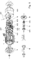
- the brake motor has a rotor shaft 18, which is mounted in the bearing plate 9 via a bearing 10.
- This bearing plate 9 is screw-connected to the housing part 12, which has cooling fins 11.
- the laminated stator core is non-positively connected, in particular also detachably connected, shrunk and / or cast with casting compound.
- Associated stator windings are provided in recesses of the stator lamination stack, wherein in FIG. 1 the deflection regions 8 of the stator windings are visible.
- a first and axially below a second brake is arranged, wherein the brakes are electromagnetically actuated.
- a fan is provided at the axial end portion of the motor for Cooling the brakes and the engine.
- the cooling air flow is directed along the housing of the brake motor in a substantially axial direction.
- the first of these brakes has a trained as a coil core bearing plate 14 which is screw-connected to the housing part 12, wherein a seal is interposed in the screw connection.
- the material of the end shield is magnetizable, in particular ferromagnetic.
- the brake coil winding 1 is arranged in a substantially annular recess of the bearing plate 14.
- a driver 6 so an externally toothed Veryakteil, by means of feather key in the circumferential direction positively, so rotatably connected, the external toothing is executed in the axial direction of the rotor shaft, so that provided with an internal toothing lining carrier 4 in the circumferential direction positively but in the axial direction slidably arranged.
- the lining carrier 4 has axially on both sides friction linings.
- a friction disc 5 is arranged, which is screw-connected to a housing part of the motor and thus dissipates frictional heat to this housing part.
- a 13 screw which is preferably designed as a stud screw used. This screw 13 additionally serves to guide the armature disk 3.
- the integrated design of the bearing plate 14 as a coil core also allows the direct heat dissipation of the brake coil 1 to the environment.
- the electromagnetically actuated spring-loaded brake described in the radial direction is housing-forming surrounded by the bearing plate 14th
- the electric motor is arranged, wherein it is tightly connected, so sealed by a seal.
- a second brake is arranged together with a fan and optionally with an angle sensor or angular velocity sensor.
- the first brake can be designated as a built-in brake.
- the second brake is designed in the manner of a mounting brake.
- the operation of the mounting brake is again similar to the described operation of the built-in brake.
- the mounting brake is screwed by means of the friction disc 15 to the bearing plate 14.
- the coil core 16 receives the brake coil winding 21, in the energization of the armature plate 22 is moved axially against the spring force generated by spring elements.
- On the rotatably connected to the rotor shaft 18 driver 20 is in turn rotationally fixed but axially displaceable a lining carrier 23 is provided with friction linings arranged on both sides.
- a fan 19 is arranged. To protect a screwed to the bearing plate 14 fan cover the fan 19 is provided surrounding.
- the bearing 17 is received in the bearing plate 14. Thus, this also absorbs the corresponding forces. Since the heat absorbed by the bearing plate 14 heat is dissipated directly to the environment, also the bearing 17 is accommodated for supporting the rotor shaft 18 and the material of the end shield 14 is selected and shaped such that the magnetic fields generated by the winding are guided integrated in the bearing plate 14 several technical functions.
- Attached to the bearing plate 14 on the side facing away from the engine attachment brake has an independent housing, in particular, which is formed together with the fan guard. This housing is bolted to the bearing shield at a well-defined interface. In this case, a seal is provided and a centering means, such as centering collar.
- a centering means such as centering collar.
- the attachment brake other attachments, such as comprising an angle sensor or the like, executable.
- the bearing plate 14 has a corresponding interface, so that different motors, in particular optional synchronous motor, asynchronous motor, LSPM motor, reluctance motor or the like, are connectable to the interface.
- the operation and / or action principles of the two brakes are designed differently.
- a first brake is operated with direct current and the other brake with alternating current.
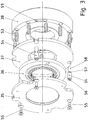
- FIG. 2 another motor is shown, here the in FIG. 3 shown pre-completed first brake is inserted into a bearing plate 41 which receives the second brake.
- the vorkomplettiere brake is in turn composed of a bobbin 38 with coil winding, supported on the compression springs 53 and an anchor plate 37 axially push away from the bobbin 38 when the coil winding is de-energized.
- the armature disk 37 is guided by axially extending guide parts 54 and pressed onto the lining carrier 36, which has friction linings on both sides and is pressed onto the friction disk 35.
- the precompletion causes the in FIG. 3 shown brake can be transported as such and forms a storable unit, that is held together.
- the guide members 54 on a first axial portion which serves for guidance, that is cylindrical and smooth running on the outside.
- an external thread 58 is provided, with which the respective guide part 54 in the Bobbin 38 is screwed, in particular in a respective threaded bore 59 of the bobbin 38th
- An internal hexagon 56 is arranged on the axial end region of the guide part 54 facing away from the axial external thread region, with the result that the guide part 54 can be screwed into a correspondingly assigned threaded bore 59 of the coil body 38 with a hexagonal tool.
- an internally threaded bore is provided, into which screws 55 can be screwed.
- the friction plate 35 is pressed by the screws 55 against a shoulder of the guide member and thus determines the distance between the friction plate 35 and spool core 38.
- the brake is held together as a unit despite the axial mobility of the armature disc 37.
- the lining carrier 36 is secured against falling out of the brake by circumferentially three or more guide members 54 are provided, which are arranged on a diameter which is larger is the outer diameter of the lining carrier 36.
- the terminal box 505 can be screwed onto the bearing plate 41.
- the extended bearing plate 41 receives the pre-completed brake (36, 37, 38, 504) and is bolted to the stator housing portion 502 of the synchronous motor.
- this Statorgekoruseteil is completed by means of a bearing plate 501st
- the rotor shaft 31 is rotatably connected to a driver 506, which is designed with axially extending external teeth for the built-in brake, and with a driver 507, which is designed with axially extending external teeth for the mounting brake.
- the precompleted brake after FIG. 3 is screw-connected with the axially extended executed bearing plate of the second brake, ie in a recess of roughly speaking cup-shaped designed bearing plate.
- the screw is performed with continuous connecting screws 40.
- the synchronous motor after FIG. 2 in turn has a rotor shaft 31 which is mounted in the bearing plate 501 via a first bearing 30.
- permanent magnets 32 are arranged on the rotor shaft, which interact with the stator windings provided on the laminated stator core 33.
- a driver 34 is again arranged on the rotor shaft 31, so that an axially movable friction lining carrier is positively connected in the circumferential direction.
- the armature disk 37 presses the lining carrier against the friction disk 35.
- this brake corresponds to the structure and operation of the precompleted brake after FIG. 2 and is now installed in the bearing plate (41, 45) as a built-in brake.
- the bearing plate (41, 45) but also takes up the bearing 43 of the rotor shaft 31.
- the bearing plate (41, 45) has a centering seat 39, on which the precompleted installation brake can be connected and thus aligned during connection.
- Attached to the bearing plate (41, 45) is a mounting brake which does not receive a bearing of the rotor shaft 31 but is arranged on the side 42 of the bearing 43 facing away from the installation brake.
- the mounting brake is constructed in a similar manner as the installation brake, so that therefore a coil core 47 is screw-connected to the bearing plate (41, 45).
- the coil core 47 accommodates a coil winding whose magnetic field attracts the armature disk when the coil winding 48 is energized.
- spring elements push the armature disk in turn on a lining carrier 50, which is axially movable and connected in the circumferential direction positively connected to a driver which is rotatably connected to the rotor shaft.
- the armature disk 44 presses the lining carrier 50 against the friction disk 51.
- the armature disk 44 is in turn axially guided, the friction disk 51 releasably connected to the spool core 47th
- an angle sensor 46 is arranged.
- a sealing washer 52 in particular made of plastic. This prevents abrasion of the lining carrier from getting into the engine area.
- the sealing washer 52 is also sealed to the rotor shaft 31, in particular with a labyrinth seal or the like.
- the engine area is sufficiently sealed from the area of the built-in brake, in particular to at least substantially prevent the penetration of abrasion into the engine area.
- FIG. 6 is shown attached to the asynchronous brake, which is designed as a built-in brake, so the housing forms on its axial end forming a housing, and sealed with the friction plate 401 to the engine with the sealing ring 607 is connected.
- a second brake is designed as a mounting brake and sealed with the bearing plate, so the housing part of the built-in brake, connected by means of the sealing ring 602.
- the mounting brake is screwed by means of screws 603 to the bearing plate (404, 14).
- a fan cover is provided housing forming, from which only the manually operable operating lever of the manual ventilation unit 601 protrudes. By means of actuation of this manual ventilation unit 601, the brake can be released, ie in the currentless case, the braking force can be switched off.
- a driver 605 with axially extending external teeth for the built-in brake and axially spaced therefrom by the bearing 17, a driver 606 is provided with axially extending external teeth for the attachment brake.
Landscapes
- Engineering & Computer Science (AREA)
- General Engineering & Computer Science (AREA)
- Physics & Mathematics (AREA)
- Electromagnetism (AREA)
- Mechanical Engineering (AREA)
- Power Engineering (AREA)
- Connection Of Motors, Electrical Generators, Mechanical Devices, And The Like (AREA)
- Braking Arrangements (AREA)
Claims (12)
- Ensemble de pièces dévolu à la fabrication de différents moteurs électriques d'une gamme de production de moteurs électriques,
ledit ensemble de pièces comprenant au moins- un premier frein,- des premier et second flasques de paliers (9, 41, 45, 404, 501),- des première et seconde parties de carter (12, 502, 503),- des première et seconde unités de montage rapporté,ladite première partie de carter (12, 502, 503) étant reliée, et pouvant notamment être reliée par vissage audit premier flasque de palier (9, 41, 45, 404, 501), formant ainsi un carter dédié à un premier moteur,
ladite seconde partie de carter (12, 502, 503) étant reliée, et pouvant notamment être reliée par vissage audit second flasque de palier (9, 41, 45, 404, 501), formant ainsi un carter dédié à un second moteur,
le premier frein étant sélectivement logé dans ledit premier ou dans ledit second flasque de palier (9, 41, 45, 404, 501), de telle sorte que le flasque de palier (9, 41, 45, 404, 501) considéré entoure ledit premier frein, avec formation d'une enceinte, et que l'arbre rotorique (18, 31) du moteur puisse être monté dans un palier intégré dans ledit flasque de palier (9, 41, 45, 404, 501),
ledit carter entourant les enroulements statoriques du moteur considéré, avec formation d'une enceinte, et étant composé de parties, notamment au moyen de liaisons vissées respectives dont l'étanchéité est assurée entre le flasque de palier (9, 41, 45, 404, 501) considéré et la partie de carter (12, 502, 503) considérée,
caractérisé par le fait que
la première, ou la seconde unité de montage rapporté inclut au moins un second frein, lequel second frein peut être rapporté sur le carter du moteur,
ledit second frein étant rapporté sur le premier, ou sur le second flasque de palier (9, 41, 45, 404, 501),
les premier et second freins étant de réalisation pré-achevée, permettant ainsi, en particulier, un contrôle fonctionnel desdits freins avant que ledit moteur ne soit intégralement assemblé avec des freins. - Ensemble de pièces conforme à la revendication 1,
caractérisé par le fait que
le premier frein peut être logé dans le carter du premier, ou du second moteur. - Ensemble de pièces conforme à l'une des revendications précédentes,
caractérisé par le fait que
le premier moteur se différencie du second moteur,
notamment en ce sens que ledit premier moteur est un moteur asynchrone, et que ledit second moteur est un moteur synchrone. - Ensemble de pièces conforme à l'une des revendications précédentes,
caractérisé par le fait que
le premier frein peut être reçu par une creusure du flasque de palier (9, 41, 45, 404, 501) considéré, revêtant substantiellement la forme d'un pot, et peut être relié par vissage, sachant notamment que ledit flasque de palier (9, 41, 45, 404, 501) considéré remplit la fonction d'une surface de freinage affectée à un porte-garniture (4, 23, 36, 50) du second frein, ledit porte-garniture (4, 23, 36, 50) étant sollicité par un disque d'induit (3, 22, 37, 44) pouvant coulisser axialement au moyen d'éléments élastiques. - Ensemble de pièces conforme à l'une des revendications précédentes,
caractérisé par le fait que
le premier, ou le second flasque de palier (9, 41, 45, 404, 501) remplit la fonction d'un noyau de bobine (16, 42, 47) de l'enroulement de l'électro-aimant du premier frein, lequel premier frein est réalisé sous la forme d'un frein à pression de ressorts pouvant être actionné électromagnétiquement. - Ensemble de pièces conforme à l'une des revendications précédentes,
caractérisé par le fait que
les première et seconde parties de carter (12, 502, 503) reçoivent un palier de l'arbre rotorique (18, 31) du moteur, sachant notamment que lesdites première et seconde parties de carter (12, 502, 503) sont réalisées en deux éléments et incluent, à cet effet, un flasque de palier (9, 41, 45, 404, 501) supplémentaire, recevant ledit palier de l'arbre rotorique (18, 31) du moteur. - Ensemble de pièces conforme à la revendication 5,
caractérisé par le fait que
l'un des freins, ou les deux freins, est (sont) réalisé(s) sous la forme d'un frein à pression de ressorts pouvant être actionné électromagnétiquement, sachant notamment que, lorsque l'électro-aimant est privé de courant, des éléments élastiques (2), prenant appui sur le corps de la bobine dudit électro-aimant, pressent un disque d'induit (3, 22, 37, 44) contre un porte-garniture (4, 23, 36, 50) qui, de ce fait, est pressé contre un disque de friction (5, 15, 35, 51, 504), ledit disque d'induit (3, 22, 37, 44) étant agencé avec verrouillage rotatif par rapport audit disque de friction (5, 15, 35, 51, 504) et audit électro-aimant, et étant apte au coulissement axial, ledit porte-garniture (4, 23, 36, 50) étant relié à l'arbre rotoriquc (18, 31) du moteur électrique avec verrouillage rotatif et faculté de coulissement axial. - Ensemble de pièces conforme à la revendication 7,
dans lequel
le disque de friction (5, 15, 35, 51, 504) est consigné à demeure avec espacement axial par rapport à un noyau de bobine (16, 42, 47) du frein, au moyen d'une pièce de guidage, laquelle pièce de guidage est notamment prévue pour le guidage axial d'un disque d'induit (3, 22, 37, 44) dudit frein, ledit disque d'induit (3, 22, 37, 44) étant limité et/ou retenu par ladite pièce de guidage dans le sens périphérique, par complémentarité de formes. - Ensemble de pièces conforme à la revendication 8,
caractérisé par le fait que
la pièce de guidage présente un premier tronçon axial dévolu au guidage du disque d'induit (3, 22, 37, 44), et comporte un second tronçon axial muni d'un filetage extérieur, en vue du vissage dans un perçage taraudé du noyau de bobine (16, 42, 47). - Ensemble de pièces conforme à la revendication 8,
caractérisé par le fait
qu'une configuration à six pans creux est prévue dans une région extrême axiale de la pièce de guidage, notamment de façon telle que ladite pièce de guidage puisse être vissée, au moyen d'un outil hexagonal, dans un perçage taraudé du noyau de bobine (16, 42, 47). - Ensemble de pièces conforme à la revendication 8,
caractérisé par le fait que
la pièce de guidage est pourvue d'un évidement à filetage intérieur, de sorte qu'un disque de friction (5, 15, 35, 51, 504) du frein peut être relié par vissage à ladite pièce de guidage, au moyen d'une vis, et peut notamment être bloqué à demeure contre un décrochement ménagé sur le pourtour extérieur de ladite pièce de guidage ;
et/ou par le fait
qu'un disque d'étanchement est interposé entre une zone spatiale incluant le premier frein et une zone spatiale incluant le stator, et est notamment doté, en direction de l'arbre rotorique (18, 31), d'une garniture d'étanchement telle qu'un joint d'étanchement à labyrinthe. - Procédé destiné à la fabrication de différents moteurs électriques à partir d'un ensemble de pièces conforme à l'une des revendications précédentes,
ledit ensemble de pièces comprenant au moins- un premier frein,- des premier et second flasques de paliers,- des première et seconde parties de carter (12, 502, 503),- des première et seconde unités de montage rapporté,caractérisé par le fait que,
de manière sélective,
en vue de former un premier moteur électrique, la première partie de carter est reliée, notamment reliée par vissage au premier flasque de palier, formant ainsi un carter dédié audit premier moteur, le premier frein étant logé dans ledit premier flasque de palier, de telle sorte que ledit premier flasque de palier entoure ledit premier frein, avec formation d'une enceinte, et que l'arbre rotorique (18, 31) dudit moteur puisse être monté dans un palier intégré dans ledit premier flasque de palier,
en vue de former un second moteur électrique, la seconde partie de carter est reliée, notamment reliée par vissage au second flasque de palier, formant ainsi un carter dédié audit second moteur, le premier frein étant logé dans ledit second flasque de palier, de telle sorte que ledit second flasque de palier entoure ledit premier frein, avec formation d'une enceinte, et que l'arbre rotorique (18, 31) dudit moteur puisse être monté dans un palier intégré dans ledit second flasque de palier,
sachant que le carter, respectivement formé, entoure les enroulements statoriques du moteur considéré, avec formation d'une enceinte, et est composé de parties, notamment au moyen de liaisons vissées respectives dont l'étanchéité est assurée entre le flasque de palier considéré et la partie de carter considérée,
sachant notamment qu'une première unité de montage rapporté est reliée, notamment reliée par vissage audit premier flasque de palier,
et qu'une seconde unité de montage rapporté est reliée, notamment reliée par vissage audit second flasque de palier,
la première, ou la seconde unité de montage rapporté incluant au moins un second frein, lequel second frein est respectivement rapporté sur le premier, ou sur le second flasque de palier, sachant notamment que lesdites première et seconde unités de montage rapporté sont différentes.
Applications Claiming Priority (2)
| Application Number | Priority Date | Filing Date | Title |
|---|---|---|---|
| DE102010049747.9A DE102010049747B4 (de) | 2010-10-29 | 2010-10-29 | Bausatz zur Herstellung unterschiedlicher Elektromotoren einer Baureihe von Elektromotoren und Verfahren zur Herstellung |
| PCT/EP2011/004679 WO2012055463A2 (fr) | 2010-10-29 | 2011-09-19 | Ensemble pour la fabrication de moteurs électriques différents d'une série de moteurs électriques et procédé de fabrication |
Publications (2)
| Publication Number | Publication Date |
|---|---|
| EP2633604A2 EP2633604A2 (fr) | 2013-09-04 |
| EP2633604B1 true EP2633604B1 (fr) | 2017-04-19 |
Family
ID=44735872
Family Applications (1)
| Application Number | Title | Priority Date | Filing Date |
|---|---|---|---|
| EP11764103.5A Active EP2633604B1 (fr) | 2010-10-29 | 2011-09-19 | Ensemble pour la fabrication de moteurs électriques différents d'une série de moteurs électriques et procédé de fabrication |
Country Status (3)
| Country | Link |
|---|---|
| EP (1) | EP2633604B1 (fr) |
| DE (1) | DE102010049747B4 (fr) |
| WO (1) | WO2012055463A2 (fr) |
Cited By (2)
| Publication number | Priority date | Publication date | Assignee | Title |
|---|---|---|---|---|
| USD853963S1 (en) * | 2016-10-28 | 2019-07-16 | Siemens Aktiengesellschaft | Electric motor |
| WO2023237223A1 (fr) * | 2022-06-06 | 2023-12-14 | Sew-Eurodrive Gmbh & Co. Kg | Motoréducteur et système comprenant une électronique de commande et un motoréducteur |
Families Citing this family (12)
| Publication number | Priority date | Publication date | Assignee | Title |
|---|---|---|---|---|
| DE102012019001B4 (de) * | 2012-09-27 | 2014-05-28 | Sew-Eurodrive Gmbh & Co Kg | Elektromagnetisch betätigbare Bremsanordnung und Elektromotor |
| DE102012019415B4 (de) * | 2012-10-04 | 2023-12-21 | Sew-Eurodrive Gmbh & Co Kg | Elektromotor, insbesondere mit einer redundanten Bremsanordnung |
| WO2023099025A1 (fr) | 2021-11-30 | 2023-06-08 | Sew-Eurodrive Gmbh & Co. Kg | Entraînement comprenant une transmission dotée d'un carter de transmission, ensemble frein à actionnement électromagnétique et moteur électrique |
| EP4441386A1 (fr) | 2021-11-30 | 2024-10-09 | SEW-EURODRIVE GmbH & Co. KG | Entraînement présentant une transmission dotée d'un carter de transmission, ensemble frein à actionnement électromagnétique et moteur électrique |
| DE102022004230B4 (de) | 2021-11-30 | 2026-04-02 | Sew-Eurodrive Gmbh & Co Kg | Antrieb, aufweisend ein Getriebe mit einem Getriebegehäuse, eine elektromagnetisch betätigbare Bremsanordnung und einen Elektromotor |
| EP4441875A1 (fr) | 2021-11-30 | 2024-10-09 | Sew-Eurodrive GmbH & Co. KG | Entraînement comprenant une transmission avec un carter de transmission, ensemble frein à actionnement électromagnétique et moteur électrique |
| WO2023099027A1 (fr) | 2021-11-30 | 2023-06-08 | Sew-Eurodrive Gmbh & Co. | Entraînement comprenant une transmission comprenant un carter de transmission, ensemble frein à actionnement électromagnétique et moteur électrique |
| EP4537443A1 (fr) | 2022-06-08 | 2025-04-16 | Sew-Eurodrive GmbH & Co. KG | Moteur à engrenages doté d'un frein |
| DE102024000140A1 (de) | 2023-02-15 | 2024-08-22 | Sew-Eurodrive Gmbh & Co Kg | Elektromagnetisch betätigbare Bremse und Elektromotor mit elektromagnetisch betätigbarer Bremse |
| EP4680873A1 (fr) | 2023-03-14 | 2026-01-21 | SEW-EURODRIVE GmbH & Co. KG | Ensemble frein, en particulier pour un moteur électrique, pour freiner un arbre |
| CN120826862A (zh) | 2023-03-20 | 2025-10-21 | 索尤若驱动有限及两合公司 | 可电磁操纵的制动器和具有可电磁操纵的制动器的电机 |
| CN116260294B (zh) * | 2023-05-15 | 2023-08-11 | 长沙锐博特科技有限公司 | 一种汽车电机定子自动压装设备 |
Family Cites Families (7)
| Publication number | Priority date | Publication date | Assignee | Title |
|---|---|---|---|---|
| GB779349A (en) * | 1952-10-17 | 1957-07-17 | Robert Gilmour Letourneau | Improvements in electromagnetic brakes |
| US3338349A (en) * | 1966-11-17 | 1967-08-29 | Warner Electric Brake & Clutch | Electric motor mounted magnetic friction brake |
| DE19838171B4 (de) * | 1998-05-14 | 2006-04-06 | Sew-Eurodrive Gmbh & Co. Kg | Elektromotor mit Bremse |
| FR2857348B1 (fr) * | 2003-07-08 | 2005-12-02 | Leroy Somer Moteurs | Systeme de freinage a reprise de couple securisee |
| TWI272757B (en) * | 2003-11-20 | 2007-02-01 | Sumitomo Heavy Industries | Motor built-in cylinder |
| DE102004063920B4 (de) * | 2004-04-01 | 2022-12-15 | Sew-Eurodrive Gmbh & Co Kg | Elektromotor |
| DE102009005885A1 (de) * | 2009-01-23 | 2010-07-29 | Robert Bosch Gmbh | Servoantrieb und Verfahren zum Herstellen eines Servoantriebs |
-
2010
- 2010-10-29 DE DE102010049747.9A patent/DE102010049747B4/de active Active
-
2011
- 2011-09-19 WO PCT/EP2011/004679 patent/WO2012055463A2/fr not_active Ceased
- 2011-09-19 EP EP11764103.5A patent/EP2633604B1/fr active Active
Cited By (4)
| Publication number | Priority date | Publication date | Assignee | Title |
|---|---|---|---|---|
| USD853963S1 (en) * | 2016-10-28 | 2019-07-16 | Siemens Aktiengesellschaft | Electric motor |
| USD860942S1 (en) | 2016-10-28 | 2019-09-24 | Siemens Aktiengesellschaft | Electric motor |
| USD871335S1 (en) | 2016-10-28 | 2019-12-31 | Siemens Aktiengesellschaft | Electric motor |
| WO2023237223A1 (fr) * | 2022-06-06 | 2023-12-14 | Sew-Eurodrive Gmbh & Co. Kg | Motoréducteur et système comprenant une électronique de commande et un motoréducteur |
Also Published As
| Publication number | Publication date |
|---|---|
| DE102010049747B4 (de) | 2021-05-06 |
| WO2012055463A2 (fr) | 2012-05-03 |
| WO2012055463A3 (fr) | 2013-05-10 |
| EP2633604A2 (fr) | 2013-09-04 |
| DE102010049747A1 (de) | 2012-05-03 |
Similar Documents
| Publication | Publication Date | Title |
|---|---|---|
| EP2633603B1 (fr) | Moteur électrique | |
| EP2633605B1 (fr) | Frein | |
| DE102010049747B4 (de) | Bausatz zur Herstellung unterschiedlicher Elektromotoren einer Baureihe von Elektromotoren und Verfahren zur Herstellung | |
| DE102012019415B4 (de) | Elektromotor, insbesondere mit einer redundanten Bremsanordnung | |
| EP3271996B1 (fr) | Moteur électrique | |
| DE112013004395T5 (de) | Variabler Reluktanzresolver mit integraler elektromagnetischer Störabschirmung und rotierende elektrische Maschine mit diesem | |
| EP2617123B1 (fr) | Moteur électrique | |
| EP2061141A1 (fr) | Machine électrique dotée de freins magnétiques directement sur le rotor | |
| DE102014203944A1 (de) | Läufereinheit für eine elektrische Maschine sowie elektrische Maschine | |
| DE102014012348B4 (de) | Elektromotor, aufweisend einen Stator und einen Rotor, und Verfahren zum Herstellen einer elektromotorisch angetriebenen Maschine | |
| DE3508227C1 (de) | Elektromagnetisch betaetigbare Reibungsbrems- und Kupplungsvorrichtung fuer einen elektromotorischen Antrieb,insbesondere fuer Industrie-Naehmaschinen | |
| DE60205878T2 (de) | Brems-kupplung anordnung | |
| EP2901037B1 (fr) | Système de frein et moteur électrique équipé d'un système de frein | |
| DE102015005230A1 (de) | Elektromotor mit Sensoranordnung und elektromagnetisch betätigbarer Bremse | |
| DE102015001647A1 (de) | Bremsanordnung | |
| EP2504600B1 (fr) | Frein à actionnement électromagnétique et procédé pour faire fonctionner un frein | |
| EP2275700B1 (fr) | Embrayage à friction électromagnétique | |
| EP3289670A1 (fr) | Système de transmission | |
| DE102022002717A1 (de) | Elektromotor mit Bremsanordnung | |
| WO2008141998A1 (fr) | Unité de freinage pour machine électrique, flasque comprenant une unité de freinage de ce type et machine électrique | |
| DE102025133801A1 (de) | Elektromagnetisch betätigbare Bremsanordnung mit einer abzubremsenden Welle | |
| DE102024104584A1 (de) | Elektromagnetisch betätigbare Bremse und Elektromotor mit elektromagnetisch betätigbarer Bremse | |
| WO2015188968A1 (fr) | Moteur électrique comprenant des moyens de support |
Legal Events
| Date | Code | Title | Description |
|---|---|---|---|
| PUAI | Public reference made under article 153(3) epc to a published international application that has entered the european phase |
Free format text: ORIGINAL CODE: 0009012 |
|
| AK | Designated contracting states |
Kind code of ref document: A2 Designated state(s): AL AT BE BG CH CY CZ DE DK EE ES FI FR GB GR HR HU IE IS IT LI LT LU LV MC MK MT NL NO PL PT RO RS SE SI SK SM TR |
|
| AX | Request for extension of the european patent |
Extension state: BA ME |
|
| 17P | Request for examination filed |
Effective date: 20131111 |
|
| RBV | Designated contracting states (corrected) |
Designated state(s): AL AT BE BG CH CY CZ DE DK EE ES FI FR GB GR HR HU IE IS IT LI LT LU LV MC MK MT NL NO PL PT RO RS SE SI SK SM TR |
|
| DAX | Request for extension of the european patent (deleted) | ||
| GRAP | Despatch of communication of intention to grant a patent |
Free format text: ORIGINAL CODE: EPIDOSNIGR1 |
|
| INTG | Intention to grant announced |
Effective date: 20161202 |
|
| GRAS | Grant fee paid |
Free format text: ORIGINAL CODE: EPIDOSNIGR3 |
|
| GRAA | (expected) grant |
Free format text: ORIGINAL CODE: 0009210 |
|
| AK | Designated contracting states |
Kind code of ref document: B1 Designated state(s): AL AT BE BG CH CY CZ DE DK EE ES FI FR GB GR HR HU IE IS IT LI LT LU LV MC MK MT NL NO PL PT RO RS SE SI SK SM TR |
|
| REG | Reference to a national code |
Ref country code: GB Ref legal event code: FG4D Free format text: NOT ENGLISH |
|
| REG | Reference to a national code |
Ref country code: CH Ref legal event code: EP Ref country code: CH Ref legal event code: NV Representative=s name: HEPP WENGER RYFFEL AG, CH |
|
| REG | Reference to a national code |
Ref country code: AT Ref legal event code: REF Ref document number: 886802 Country of ref document: AT Kind code of ref document: T Effective date: 20170515 |
|
| REG | Reference to a national code |
Ref country code: IE Ref legal event code: FG4D Free format text: LANGUAGE OF EP DOCUMENT: GERMAN |
|
| REG | Reference to a national code |
Ref country code: DE Ref legal event code: R096 Ref document number: 502011012087 Country of ref document: DE |
|
| REG | Reference to a national code |
Ref country code: FR Ref legal event code: PLFP Year of fee payment: 7 |
|
| REG | Reference to a national code |
Ref country code: NL Ref legal event code: MP Effective date: 20170419 |
|
| REG | Reference to a national code |
Ref country code: LT Ref legal event code: MG4D |
|
| PG25 | Lapsed in a contracting state [announced via postgrant information from national office to epo] |
Ref country code: NL Free format text: LAPSE BECAUSE OF FAILURE TO SUBMIT A TRANSLATION OF THE DESCRIPTION OR TO PAY THE FEE WITHIN THE PRESCRIBED TIME-LIMIT Effective date: 20170419 |
|
| PG25 | Lapsed in a contracting state [announced via postgrant information from national office to epo] |
Ref country code: FI Free format text: LAPSE BECAUSE OF FAILURE TO SUBMIT A TRANSLATION OF THE DESCRIPTION OR TO PAY THE FEE WITHIN THE PRESCRIBED TIME-LIMIT Effective date: 20170419 Ref country code: HR Free format text: LAPSE BECAUSE OF FAILURE TO SUBMIT A TRANSLATION OF THE DESCRIPTION OR TO PAY THE FEE WITHIN THE PRESCRIBED TIME-LIMIT Effective date: 20170419 Ref country code: GR Free format text: LAPSE BECAUSE OF FAILURE TO SUBMIT A TRANSLATION OF THE DESCRIPTION OR TO PAY THE FEE WITHIN THE PRESCRIBED TIME-LIMIT Effective date: 20170720 Ref country code: ES Free format text: LAPSE BECAUSE OF FAILURE TO SUBMIT A TRANSLATION OF THE DESCRIPTION OR TO PAY THE FEE WITHIN THE PRESCRIBED TIME-LIMIT Effective date: 20170419 Ref country code: LT Free format text: LAPSE BECAUSE OF FAILURE TO SUBMIT A TRANSLATION OF THE DESCRIPTION OR TO PAY THE FEE WITHIN THE PRESCRIBED TIME-LIMIT Effective date: 20170419 Ref country code: NO Free format text: LAPSE BECAUSE OF FAILURE TO SUBMIT A TRANSLATION OF THE DESCRIPTION OR TO PAY THE FEE WITHIN THE PRESCRIBED TIME-LIMIT Effective date: 20170719 |
|
| PG25 | Lapsed in a contracting state [announced via postgrant information from national office to epo] |
Ref country code: PL Free format text: LAPSE BECAUSE OF FAILURE TO SUBMIT A TRANSLATION OF THE DESCRIPTION OR TO PAY THE FEE WITHIN THE PRESCRIBED TIME-LIMIT Effective date: 20170419 Ref country code: IS Free format text: LAPSE BECAUSE OF FAILURE TO SUBMIT A TRANSLATION OF THE DESCRIPTION OR TO PAY THE FEE WITHIN THE PRESCRIBED TIME-LIMIT Effective date: 20170819 Ref country code: BG Free format text: LAPSE BECAUSE OF FAILURE TO SUBMIT A TRANSLATION OF THE DESCRIPTION OR TO PAY THE FEE WITHIN THE PRESCRIBED TIME-LIMIT Effective date: 20170719 Ref country code: RS Free format text: LAPSE BECAUSE OF FAILURE TO SUBMIT A TRANSLATION OF THE DESCRIPTION OR TO PAY THE FEE WITHIN THE PRESCRIBED TIME-LIMIT Effective date: 20170419 Ref country code: LV Free format text: LAPSE BECAUSE OF FAILURE TO SUBMIT A TRANSLATION OF THE DESCRIPTION OR TO PAY THE FEE WITHIN THE PRESCRIBED TIME-LIMIT Effective date: 20170419 Ref country code: SE Free format text: LAPSE BECAUSE OF FAILURE TO SUBMIT A TRANSLATION OF THE DESCRIPTION OR TO PAY THE FEE WITHIN THE PRESCRIBED TIME-LIMIT Effective date: 20170419 |
|
| REG | Reference to a national code |
Ref country code: DE Ref legal event code: R097 Ref document number: 502011012087 Country of ref document: DE |
|
| PG25 | Lapsed in a contracting state [announced via postgrant information from national office to epo] |
Ref country code: EE Free format text: LAPSE BECAUSE OF FAILURE TO SUBMIT A TRANSLATION OF THE DESCRIPTION OR TO PAY THE FEE WITHIN THE PRESCRIBED TIME-LIMIT Effective date: 20170419 Ref country code: CZ Free format text: LAPSE BECAUSE OF FAILURE TO SUBMIT A TRANSLATION OF THE DESCRIPTION OR TO PAY THE FEE WITHIN THE PRESCRIBED TIME-LIMIT Effective date: 20170419 Ref country code: DK Free format text: LAPSE BECAUSE OF FAILURE TO SUBMIT A TRANSLATION OF THE DESCRIPTION OR TO PAY THE FEE WITHIN THE PRESCRIBED TIME-LIMIT Effective date: 20170419 Ref country code: SK Free format text: LAPSE BECAUSE OF FAILURE TO SUBMIT A TRANSLATION OF THE DESCRIPTION OR TO PAY THE FEE WITHIN THE PRESCRIBED TIME-LIMIT Effective date: 20170419 Ref country code: RO Free format text: LAPSE BECAUSE OF FAILURE TO SUBMIT A TRANSLATION OF THE DESCRIPTION OR TO PAY THE FEE WITHIN THE PRESCRIBED TIME-LIMIT Effective date: 20170419 |
|
| PLBE | No opposition filed within time limit |
Free format text: ORIGINAL CODE: 0009261 |
|
| STAA | Information on the status of an ep patent application or granted ep patent |
Free format text: STATUS: NO OPPOSITION FILED WITHIN TIME LIMIT |
|
| PG25 | Lapsed in a contracting state [announced via postgrant information from national office to epo] |
Ref country code: SM Free format text: LAPSE BECAUSE OF FAILURE TO SUBMIT A TRANSLATION OF THE DESCRIPTION OR TO PAY THE FEE WITHIN THE PRESCRIBED TIME-LIMIT Effective date: 20170419 |
|
| 26N | No opposition filed |
Effective date: 20180122 |
|
| PG25 | Lapsed in a contracting state [announced via postgrant information from national office to epo] |
Ref country code: MC Free format text: LAPSE BECAUSE OF FAILURE TO SUBMIT A TRANSLATION OF THE DESCRIPTION OR TO PAY THE FEE WITHIN THE PRESCRIBED TIME-LIMIT Effective date: 20170419 Ref country code: SI Free format text: LAPSE BECAUSE OF FAILURE TO SUBMIT A TRANSLATION OF THE DESCRIPTION OR TO PAY THE FEE WITHIN THE PRESCRIBED TIME-LIMIT Effective date: 20170419 |
|
| REG | Reference to a national code |
Ref country code: IE Ref legal event code: MM4A |
|
| REG | Reference to a national code |
Ref country code: BE Ref legal event code: MM Effective date: 20170930 |
|
| PG25 | Lapsed in a contracting state [announced via postgrant information from national office to epo] |
Ref country code: LU Free format text: LAPSE BECAUSE OF NON-PAYMENT OF DUE FEES Effective date: 20170919 |
|
| PG25 | Lapsed in a contracting state [announced via postgrant information from national office to epo] |
Ref country code: IE Free format text: LAPSE BECAUSE OF NON-PAYMENT OF DUE FEES Effective date: 20170919 |
|
| REG | Reference to a national code |
Ref country code: FR Ref legal event code: PLFP Year of fee payment: 8 |
|
| PG25 | Lapsed in a contracting state [announced via postgrant information from national office to epo] |
Ref country code: BE Free format text: LAPSE BECAUSE OF NON-PAYMENT OF DUE FEES Effective date: 20170930 |
|
| PG25 | Lapsed in a contracting state [announced via postgrant information from national office to epo] |
Ref country code: MT Free format text: LAPSE BECAUSE OF FAILURE TO SUBMIT A TRANSLATION OF THE DESCRIPTION OR TO PAY THE FEE WITHIN THE PRESCRIBED TIME-LIMIT Effective date: 20170419 |
|
| PG25 | Lapsed in a contracting state [announced via postgrant information from national office to epo] |
Ref country code: HU Free format text: LAPSE BECAUSE OF FAILURE TO SUBMIT A TRANSLATION OF THE DESCRIPTION OR TO PAY THE FEE WITHIN THE PRESCRIBED TIME-LIMIT; INVALID AB INITIO Effective date: 20110919 |
|
| PG25 | Lapsed in a contracting state [announced via postgrant information from national office to epo] |
Ref country code: CY Free format text: LAPSE BECAUSE OF NON-PAYMENT OF DUE FEES Effective date: 20170419 |
|
| PG25 | Lapsed in a contracting state [announced via postgrant information from national office to epo] |
Ref country code: MK Free format text: LAPSE BECAUSE OF FAILURE TO SUBMIT A TRANSLATION OF THE DESCRIPTION OR TO PAY THE FEE WITHIN THE PRESCRIBED TIME-LIMIT Effective date: 20170419 |
|
| PG25 | Lapsed in a contracting state [announced via postgrant information from national office to epo] |
Ref country code: TR Free format text: LAPSE BECAUSE OF FAILURE TO SUBMIT A TRANSLATION OF THE DESCRIPTION OR TO PAY THE FEE WITHIN THE PRESCRIBED TIME-LIMIT Effective date: 20170419 |
|
| PG25 | Lapsed in a contracting state [announced via postgrant information from national office to epo] |
Ref country code: PT Free format text: LAPSE BECAUSE OF FAILURE TO SUBMIT A TRANSLATION OF THE DESCRIPTION OR TO PAY THE FEE WITHIN THE PRESCRIBED TIME-LIMIT Effective date: 20170419 |
|
| PG25 | Lapsed in a contracting state [announced via postgrant information from national office to epo] |
Ref country code: AL Free format text: LAPSE BECAUSE OF FAILURE TO SUBMIT A TRANSLATION OF THE DESCRIPTION OR TO PAY THE FEE WITHIN THE PRESCRIBED TIME-LIMIT Effective date: 20170419 |
|
| REG | Reference to a national code |
Ref country code: CH Ref legal event code: U11 Free format text: ST27 STATUS EVENT CODE: U-0-0-U10-U11 (AS PROVIDED BY THE NATIONAL OFFICE) Effective date: 20251001 |
|
| PGFP | Annual fee paid to national office [announced via postgrant information from national office to epo] |
Ref country code: DE Payment date: 20250930 Year of fee payment: 15 |
|
| PGFP | Annual fee paid to national office [announced via postgrant information from national office to epo] |
Ref country code: IT Payment date: 20250825 Year of fee payment: 15 |
|
| PGFP | Annual fee paid to national office [announced via postgrant information from national office to epo] |
Ref country code: GB Payment date: 20250731 Year of fee payment: 15 |
|
| PGFP | Annual fee paid to national office [announced via postgrant information from national office to epo] |
Ref country code: AT Payment date: 20250909 Year of fee payment: 15 Ref country code: FR Payment date: 20250808 Year of fee payment: 15 |
|
| PGFP | Annual fee paid to national office [announced via postgrant information from national office to epo] |
Ref country code: CH Payment date: 20251001 Year of fee payment: 15 |
|
| REG | Reference to a national code |
Ref country code: DE Ref legal event code: R084 Ref document number: 502011012087 Country of ref document: DE |