EP2634113B1 - Récipient pour fil de soudage avec structure conique centrale - Google Patents
Récipient pour fil de soudage avec structure conique centrale Download PDFInfo
- Publication number
- EP2634113B1 EP2634113B1 EP20120157734 EP12157734A EP2634113B1 EP 2634113 B1 EP2634113 B1 EP 2634113B1 EP 20120157734 EP20120157734 EP 20120157734 EP 12157734 A EP12157734 A EP 12157734A EP 2634113 B1 EP2634113 B1 EP 2634113B1
- Authority
- EP
- European Patent Office
- Prior art keywords
- elongated elements
- previous
- container according
- central
- bottom structure
- Prior art date
- Legal status (The legal status is an assumption and is not a legal conclusion. Google has not performed a legal analysis and makes no representation as to the accuracy of the status listed.)
- Not-in-force
Links
- 238000003466 welding Methods 0.000 title claims description 42
- 230000002093 peripheral effect Effects 0.000 claims description 32
- 229910000831 Steel Inorganic materials 0.000 claims description 7
- 239000010959 steel Substances 0.000 claims description 7
- 229910001220 stainless steel Inorganic materials 0.000 claims description 6
- 239000010935 stainless steel Substances 0.000 claims description 6
- 239000007769 metal material Substances 0.000 claims description 3
- 238000000034 method Methods 0.000 description 9
- 238000004806 packaging method and process Methods 0.000 description 4
- 238000010891 electric arc Methods 0.000 description 3
- 239000000463 material Substances 0.000 description 3
- HCHKCACWOHOZIP-UHFFFAOYSA-N Zinc Chemical compound [Zn] HCHKCACWOHOZIP-UHFFFAOYSA-N 0.000 description 2
- 239000011248 coating agent Substances 0.000 description 2
- 238000000576 coating method Methods 0.000 description 2
- 229910052725 zinc Inorganic materials 0.000 description 2
- 239000011701 zinc Substances 0.000 description 2
- 230000007423 decrease Effects 0.000 description 1
- 230000007547 defect Effects 0.000 description 1
- 238000000605 extraction Methods 0.000 description 1
- 230000004907 flux Effects 0.000 description 1
- 239000002184 metal Substances 0.000 description 1
- 229910052751 metal Inorganic materials 0.000 description 1
- 229920000642 polymer Polymers 0.000 description 1
- 239000002861 polymer material Substances 0.000 description 1
- 239000008259 solid foam Substances 0.000 description 1
Images

Classifications
-
- B—PERFORMING OPERATIONS; TRANSPORTING
- B65—CONVEYING; PACKING; STORING; HANDLING THIN OR FILAMENTARY MATERIAL
- B65D—CONTAINERS FOR STORAGE OR TRANSPORT OF ARTICLES OR MATERIALS, e.g. BAGS, BARRELS, BOTTLES, BOXES, CANS, CARTONS, CRATES, DRUMS, JARS, TANKS, HOPPERS, FORWARDING CONTAINERS; ACCESSORIES, CLOSURES, OR FITTINGS THEREFOR; PACKAGING ELEMENTS; PACKAGES
- B65D85/00—Containers, packaging elements or packages, specially adapted for particular articles or materials
- B65D85/02—Containers, packaging elements or packages, specially adapted for particular articles or materials for annular articles
- B65D85/04—Containers, packaging elements or packages, specially adapted for particular articles or materials for annular articles for coils of wire, rope or hose
-
- B—PERFORMING OPERATIONS; TRANSPORTING
- B23—MACHINE TOOLS; METAL-WORKING NOT OTHERWISE PROVIDED FOR
- B23K—SOLDERING OR UNSOLDERING; WELDING; CLADDING OR PLATING BY SOLDERING OR WELDING; CUTTING BY APPLYING HEAT LOCALLY, e.g. FLAME CUTTING; WORKING BY LASER BEAM
- B23K9/00—Arc welding or cutting
- B23K9/12—Automatic feeding or moving of electrodes or work for spot or seam welding or cutting
- B23K9/133—Means for feeding electrodes, e.g. drums, rolls, motors
- B23K9/1333—Dereeling means
-
- B—PERFORMING OPERATIONS; TRANSPORTING
- B65—CONVEYING; PACKING; STORING; HANDLING THIN OR FILAMENTARY MATERIAL
- B65H—HANDLING THIN OR FILAMENTARY MATERIAL, e.g. SHEETS, WEBS, CABLES
- B65H57/00—Guides for filamentary materials; Supports therefor
- B65H57/18—Guides for filamentary materials; Supports therefor mounted to facilitate unwinding of material from packages
-
- B—PERFORMING OPERATIONS; TRANSPORTING
- B65—CONVEYING; PACKING; STORING; HANDLING THIN OR FILAMENTARY MATERIAL
- B65H—HANDLING THIN OR FILAMENTARY MATERIAL, e.g. SHEETS, WEBS, CABLES
- B65H75/00—Storing webs, tapes, or filamentary material, e.g. on reels
- B65H75/02—Cores, formers, supports, or holders for coiled, wound, or folded material, e.g. reels, spindles, bobbins, cop tubes, cans, mandrels or chucks
- B65H75/04—Kinds or types
- B65H75/16—Cans or receptacles, e.g. sliver cans
-
- B—PERFORMING OPERATIONS; TRANSPORTING
- B65—CONVEYING; PACKING; STORING; HANDLING THIN OR FILAMENTARY MATERIAL
- B65H—HANDLING THIN OR FILAMENTARY MATERIAL, e.g. SHEETS, WEBS, CABLES
- B65H2701/00—Handled material; Storage means
- B65H2701/30—Handled filamentary material
- B65H2701/36—Wires
Definitions
- the present invention relates to a container or drum for packaging, storing, transporting and unwinding a coil or spool of welding wire, and the use of such a container in a welding operation, preferably an electric arc welding process, such as a MIG or MAG welding process.
- One of the major problems encountered in automatic or robotic welding is the control of the welding wire as it is withdrawn from a drum.
- twists in the wire are created by the spooling process as the wire is withdrawn from the drum.
- twists are a serious issue since they are often involved in subsequent welding defects or quality of the welding joints thus obtained.
- the operator when using a welding wire drum, the operator should be able to easily detect when the wire is coming to an end so that the operator can intervene as soon as possible to replace an empty drum with a new one. This should be done without the operator having to open the cover of the drum.
- EP-A-519424 discloses a container with a retainer device placed on the top of the coil and having an outer periphery matching the diameter of the inner wall of the container and an inner bell-mouthed portion defining a wire extraction opening.
- the retainer can freely descend in the container in contact with the coil as the height of the coil decreases as the wire is being unwound from the coil.
- EP-A-636098 teaches to use of a square box with an internal flat cover arranged on the wire coil and matching the internal shape of the box so as to retain the welding wire and avoid or limit the twists.
- EP-A-1053189 discloses a polygonal box-like body for accommodating a circular coil of wire during the transportation and the unwinding of the coil and a retainer device arranged inside the body on the coil for preventing accidental entanglement of the wire turn during the unwinding of the wire from an upper end of the coil and a wire conduit device for the guiding the wire out from the body during the unwinding.
- EP-A-1693139 discloses a drum for a welding wire coil comprising a wire holding device positioned on the coil for holding the loops in position during an unwinding of the wire.
- the holding device has a rigid central disc and a flexible cover with a dimension greater than an inner diameter of the drum so that corner portions of the cover slightly rise along an inner wall of the drum.
- EP-A-1693140 teaches a drum with a conical, tapered or pyramidal inner wall formed of oblique pieces and comprising a rigid central disc with a central orifice positioned on the coil and across which the wire passes, and further with flexible and deformable peripheral expansions projecting beyond the edge of the disc to maintain the wire loops.
- EP-A-1357059 describes a welding wire packaging formed of an internal cylindrical drum and external square box.
- a container for welding wire in accordance with the preamble of claim 1 is disclosed by WO 2009/027784 A2 .
- the solution according to the present invention is a container for welding wire comprising :
- the container of the present invention can comprise one or several of the following features:
- the container according to the invention is suitable for use in a robotic or automatic welding operation, preferably an electric arc welding process, such as a MIG or MAG welding process.
- an electric arc welding process such as a MIG or MAG welding process.
- the wire extracted from the container is fed to a welding torch that is either arranged on a welding machine or on a robotic articulated arm.
- the enclosed Figures show an embodiment of a container for packaging a coil of welding wire, such as a flux cored wire or a metal cored wire, according to the present invention.
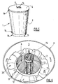
- the container according to the present invention comprises a body 1 having a peripheral wall 2 delimiting an internal volume for receiving the coil of welding wire.
- the peripheral wall 2 of the body 1 is made of cardboard material and has preferably a cylindrical shape.
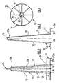
- the container of the invention further comprises a bottom structure 10 on which rests the wire coil as well as a central structure 12 comprising several elongated elements 13 fixed to the bottom structure 10 and extending upwardly in the internal volume 3 of the body 1.
- the central structure 12 made of said elongated elements 13 tapers in the upward direction.
- the elongated elements 13 are metallic rods or bars, preferably they are made of steel or of stainless steel.
- the bottom structure 10 has a circular shape or ring-shape and is made of a metallic material, preferably steel or stainless steel. It comprises a peripheral border 11 as shown in Figure 1 on to which are connected the elongated elements 13 by their first end 13a. Preferably, the elongated elements 13 are welded or screwed to the peripheral border 11 of the bottom structure 10.
- At least one of the elongated elements 13 comprises, at its second end 13b, a connection element 14 adapted for receiving the hook of a crane.
- the connection element 14 can be a loop- or a hook-like structure as visible in Figures 1 to 3 .
- connection element 14 i.e. a loop-like structure for receiving a hook as shown in Figure 3 .
- connection element 14 i.e. a loop-like structure for receiving a hook as shown in Figure 3 .
- Those two elongated elements 13 are diametrally opposed with respect to the center 23 of the structure 12 as shown in Figure 4 .
- the connection element 14 thus obtained exhibits a high resistance to breaking.
- connection element 14 can be an additional loop-like structure that is connected, preferably welded, to the second end(s) 13b of one or several elongated elements 13.
- the elongated elements 13 are connected together by a linking structure 15 arranged at their second end 13b, preferably said linking structure 15 is a ring to which are welded the elongated elements 13 as shown on Figure 1 .
- the central structure 12 comprises at least 3 elongated elements 13, preferably at least 5 elongated elements.
- 8 elongated elements constitute the central structure 12.
- the peripheral wall 2 is maintained laterally by the peripheral border 11 as said peripheral border 11 projects upwardly along a part of the external surface of the peripheral wall 2 of the body 1.
- the lower end 1b of the peripheral wall 2 of the body 1 rests, directly or indirectly, on the first portions 20 of the elongated elements 13 as illustrated in Figures 2 to 4 .
- each elongated element 13 comprises a fist portion 20 and a second portion 21 separated each other by an elbow 16.
- the first portion 20 comprises the first end 13a of each elongated element 13, whereas the second portion 21 comprises the second end 13b of each elongated element 13.
- the angle ⁇ of the elbow is greater than 90° and less than 130°, preferably less than about 110° as shown in Figure 3 .
- the body 1 further comprises a lid 4 arranged on the top 1a of the body 1, that closes the body 1.
- the lid 4 comprises a central opening 5 through which passes the connection element 14 so as to be positioned outside the body 1 when the lid 4 is positioned on the top 1a of body 1 as visible in Figure 5 .
- a welding wire coil 6 is positioned on the bottom structure 10, i.e. in the internal volume 2 of the body 1, with the elongated elements 13 of the central structure 12 extending and tapering upwardly through the middle of the wire coil 6.
- a retainer 7 with a central opening 8 is further positioned on the wire coil 6 and the elongated elements 13 extend upwardly through the central opening 8 of said retainer 7.
- the main role of the retainer 7 that is arranged on the top of the welding wire coil 6 is to maintain the wire spirals during transportation and unwinding of the coil during welding, i.e. for preventing accidental entanglement of the wire turn during the unwinding of the wire from an upper end of the coil 6.
- the retainer 7 consists of a perforated disc made of either cardboard or polymer (plastic material), steel or a combination of any two or more of these materials. Its shape or contour is preferably adapted to the inner contour of the drum body 1.
- the retainer 7 provides a constant and continuous feeding of the wire at nearly constant drawing force. The spooled wire is prevented from opening, entangling and forming loops.
- the retainer 7 can also comprise flexible or deformable additional elements 25 as represented in Figure 6 , that come into contact with the internal surface 3 of the peripheral wall 2 of body 1 thereby better maintaining the spirals of the coil 6.
- Those flexible or deformable additional elements 25 can be made of polymer material, such as plastic or a solid foam.
- the hollow body 1 of the container has an internal diameter (D) of at least 40 cm and a height (H) of at least 50 cm.
- D internal diameter
- H height
- the height is less than 200 cm and the diameter is less than 160 cm.
- the body 1 has a cylindrical shape, but according to other embodiments, it may have a different shape. It may consist in several side panels forming a peripheral wall 2 having a polygonal shape, for example a square, hexagonal or octagonal shape.
- the container or drum of the present invention can be used for packaging, storing, transporting and unwinding a coil or spool of welding wire, and said welding wire being useable in a welding operation, preferably an electric arc welding process, such as a MIG or MAG welding process, especially a robotic welding process.
- a welding operation preferably an electric arc welding process, such as a MIG or MAG welding process, especially a robotic welding process.
Landscapes
- Engineering & Computer Science (AREA)
- Mechanical Engineering (AREA)
- Physics & Mathematics (AREA)
- Plasma & Fusion (AREA)
- Packaging Of Annular Or Rod-Shaped Articles, Wearing Apparel, Cassettes, Or The Like (AREA)
- Storage Of Web-Like Or Filamentary Materials (AREA)
Claims (14)
- Récipient pour fil de soudage comprenant .- un corps (1) comprenant une paroi périphérique (2) délimitant un volume interne (3),- une structure de fond (10) comprenant une couronne périphérique (11), et- une structure centrale (12) fixée à la structure de fond (10) et s'étendant vers le haut dans le volume interne (3) du corps (1), ladite structure centrale (12) s'amincissant dans la direction ascendante,caractérisé en ce que la structure centrale (12) comprend plusieurs éléments allongés (13) qui sont raccordés à la structure de fond (10) par une première extrémité (13a) et en ce que la paroi périphérique (2) du corps (1) est aménagée sur la structure de fond (10) en étant maintenue latéralement par ladite couronne périphérique (11) de sorte que ladite couronne périphérique (11) fasse saillie vers le haut le long d'une partie de la surface externe de la paroi périphérique (2) du corps (1).
- Récipient selon la revendication précédente, caractérisé en ce que les éléments allongés (13) sont soudés à la couronnes périphérique (11) de la structure de fond (10).
- Récipient selon l'une quelconque des revendications précédentes, caractérisé en ce qu'au moins l'un des éléments allongés (13) comprend, à une seconde extrémité (13b), un élément de raccordement (14) qui est à même de recevoir un crochet d'une grue.
- Récipient selon la revendication précédente, caractérisé en ce que l'élément de raccordement (14) est une structure en forme de boucle ou de crochet.
- Récipient selon l'une quelconque des revendications précédentes, caractérisé en ce que les éléments allongés (13) sont raccordés l'un à l'autre par une structure de liaison (15) aménagée sur la seconde extrémité (13b) desdits éléments allongés (13), de préférence ladite structure de liaison (15) étant un anneau et/ou les éléments allongés (13) étant soudés à la structure de liaison (15).
- Récipient selon l'une quelconque des revendications précédentes, caractérisé en ce que la structure centrale comprend au moins 3 éléments allongés (13), de préférence au moins 5 éléments allongés.
- Récipient selon l'une quelconque des revendications précédentes, caractérisé en ce que la structure de fond (10) a une forme circulaire et/ou le corps (1) a une forme cylindrique.
- Récipient selon l'une quelconque des revendications précédentes, caractérisé en ce que les éléments allongés (13) sont des tiges ou des barres métalliques, de préférence en acier ou en acier inoxydable.
- Récipient selon l'une quelconque des revendications précédentes, caractérisé en ce que la structure de fond (10) comprenant la couronne périphérique (11) est constituée d'un matériau métallique, de préférence de l'acier ou de l'acier inoxydable.
- Récipient selon l'une quelconque des revendications précédentes, caractérisé en ce que la paroi périphérique (2) du corps (1) est constituée de carton, le corps (1) ayant une forme cylindrique.
- Récipient selon l'une quelconque des revendications précédentes, caractérisé en ce que l'extrémité inférieure (1b) de la paroi périphérique (2) du corps (1) repose, directement ou indirectement, sur les premières parties (20) des éléments allongés (13).
- Récipient selon l'une quelconque des revendications précédentes, caractérisé en ce que le corps comprend en outre un couvercle (4) aménagé au sommet (1a) du corps (1), ledit couvercle (4) comprenant une ouverture centrale (5) à travers laquelle passe l'élément de raccordement (14) de manière à être positionné à l'extérieur du corps (1) lorsque le couvercle (4) est positionné au sommet (1a) du corps (1).
- Récipient selon l'une quelconque des revendications précédentes, caractérisé en ce que chaque élément allongé (13) comprend une première partie (20) et une seconde partie (21) séparées l'une de l'autre par un coude (16), la première partie (20) comprenant la première extrémité (13a) de chaque élément allongé (13) et la seconde partie (21) comprenant la seconde extrémité (13b) de chaque élément allongé (13), de préférence l'angle α du coude étant supérieur à 90° et inférieur à 130°, de préférence inférieur à 110°.
- Récipient selon l'une quelconque des revendications précédentes, caractérisé en ce qu'une bobine de fil de soudage (6) est positionnée sur la structure de fond (10) et dans le volume interne (2) du corps (1), les éléments allongés (13) de la structure centrale (12) s'étendant vers le haut à travers le centre de la bobine de fil (6), de préférence un élément de retenue (7) avec une ouverture centrale (8) est positionné sur la bobine de fil (6), les éléments allongés (13) s'étendant également vers le haut à travers l'ouverture centrale (8) de l'élément de retenue (7).
Priority Applications (1)
| Application Number | Priority Date | Filing Date | Title |
|---|---|---|---|
| EP20120157734 EP2634113B1 (fr) | 2012-03-01 | 2012-03-01 | Récipient pour fil de soudage avec structure conique centrale |
Applications Claiming Priority (1)
| Application Number | Priority Date | Filing Date | Title |
|---|---|---|---|
| EP20120157734 EP2634113B1 (fr) | 2012-03-01 | 2012-03-01 | Récipient pour fil de soudage avec structure conique centrale |
Publications (2)
| Publication Number | Publication Date |
|---|---|
| EP2634113A1 EP2634113A1 (fr) | 2013-09-04 |
| EP2634113B1 true EP2634113B1 (fr) | 2014-10-29 |
Family
ID=45855484
Family Applications (1)
| Application Number | Title | Priority Date | Filing Date |
|---|---|---|---|
| EP20120157734 Not-in-force EP2634113B1 (fr) | 2012-03-01 | 2012-03-01 | Récipient pour fil de soudage avec structure conique centrale |
Country Status (1)
| Country | Link |
|---|---|
| EP (1) | EP2634113B1 (fr) |
Families Citing this family (1)
| Publication number | Priority date | Publication date | Assignee | Title |
|---|---|---|---|---|
| IT201900015737A1 (it) * | 2019-09-06 | 2021-03-06 | Spazzolplastica Srl | “Fusto per filo di saldatura” |
Family Cites Families (11)
| Publication number | Priority date | Publication date | Assignee | Title |
|---|---|---|---|---|
| US3729092A (en) * | 1971-03-12 | 1973-04-24 | W Marcell | Unwind support for coiled wire |
| US3778000A (en) * | 1972-07-26 | 1973-12-11 | J Breuner | Rotatable reel |
| CA2071419C (fr) | 1991-06-18 | 1996-03-19 | William Dimmett Cooper | Rondelle retenue pour contenant a bobine de fil a souder |
| IT231566Y1 (it) | 1993-02-23 | 1999-08-04 | Sidergas Srl | Contenitore di imballaggio e di svolgimento di una matassa di filo metallico |
| JPH0839142A (ja) * | 1994-08-02 | 1996-02-13 | Shinko Kosen Kogyo Kk | ワイヤロープコイリング体 |
| WO1998052844A1 (fr) | 1997-05-20 | 1998-11-26 | Esab Ab | Conteneur pour l'emballage et le deroulement d'une bobine de fil-electrode |
| ITMI20020898A1 (it) | 2002-04-24 | 2003-10-24 | Isaf S P A | Contenitore per matassa di filo per saldatura dotabile di dispositivoper collegare allo stesso una guaina di alimentazione del filo ad una |
| FR2882038A1 (fr) | 2005-02-17 | 2006-08-18 | Soudure Autogene Francaise Sa | Conteneur de conditionnement de fil de soudage avec dispositif interne de retenue des spires |
| FR2882039B1 (fr) | 2005-02-17 | 2007-04-27 | Soudure Autogene Francaise Sa | Conteneur a paroi interne oblique pour le conditionnement d'un fil de soudage |
| US7905439B2 (en) * | 2007-08-30 | 2011-03-15 | Lincoln Global, Inc. | Apparatus and method for tapered core drum package payoff |
| EP2353764A1 (fr) * | 2010-01-27 | 2011-08-10 | Oerlikon Schweisstechnik GmbH | Conteneur pour fil à souder avec un volume mort interne d'une hauteur minimale de 15 cm |
-
2012
- 2012-03-01 EP EP20120157734 patent/EP2634113B1/fr not_active Not-in-force
Also Published As
| Publication number | Publication date |
|---|---|
| EP2634113A1 (fr) | 2013-09-04 |
Similar Documents
| Publication | Publication Date | Title |
|---|---|---|
| EP2354039A1 (fr) | Conteneur pour fil de soudage avec système de rétention interne | |
| EP2256064A1 (fr) | Conteneur pour fil de soudage avec éléments allongés pour maintenir la bobine de fil | |
| CA2689419C (fr) | Bague de guidage de fil de soudage | |
| JP3955020B2 (ja) | 溶接ワイヤ繰出しドラム | |
| EP1053189B1 (fr) | Conteneur pour l'emballage et le devidage d'une bobine de fil de soudage | |
| KR100491806B1 (ko) | 대량의 와이어를 수용 및 분배하는 패키지 | |
| US20130119184A1 (en) | Floating dispensing mechanism for drum packed welding wire | |
| EP3634895B1 (fr) | Tambours de transport et de délivrance de fil | |
| CN208746503U (zh) | 存放和运输容器 | |
| CA2508395C (fr) | Emballage de fil a souder avec sangle de levage | |
| US20100230525A1 (en) | Wire dispensing apparatus for packaged wire | |
| JP2001179450A (ja) | 溶接ワイヤ収納装置 | |
| EP2189393A1 (fr) | Conteneur pour fil de soudage | |
| EP2996978B1 (fr) | Unité d'assistance à l'alimentation flottante pour le gain de fil de soudage en vrac emballé | |
| EP2612833A1 (fr) | Conteneur pour fil de soudage avec élément à poids glissant par le fil | |
| EP2634113B1 (fr) | Récipient pour fil de soudage avec structure conique centrale | |
| EP2353764A1 (fr) | Conteneur pour fil à souder avec un volume mort interne d'une hauteur minimale de 15 cm | |
| US12275049B2 (en) | Method for packing welding wire inside containers | |
| CN103771005B (zh) | 具有用于焊丝线圈的提升带的容器 | |
| HU211012B (en) | Holder for welding wire and cover plate bearing against the bobbin | |
| EP2151408B1 (fr) | Dispositif pour le conditionnement et le déroulement de câble | |
| CN202717113U (zh) | 一种线材周转桶 | |
| KR102244253B1 (ko) | 디-코일링 콘 | |
| US20140306049A1 (en) | Slip lift core for drums | |
| EP2353765A1 (fr) | Conteneur pour fil à souder avec bandes de renfort dans sa paroi périphérique |
Legal Events
| Date | Code | Title | Description |
|---|---|---|---|
| PUAI | Public reference made under article 153(3) epc to a published international application that has entered the european phase |
Free format text: ORIGINAL CODE: 0009012 |
|
| AK | Designated contracting states |
Kind code of ref document: A1 Designated state(s): AL AT BE BG CH CY CZ DE DK EE ES FI FR GB GR HR HU IE IS IT LI LT LU LV MC MK MT NL NO PL PT RO RS SE SI SK SM TR |
|
| AX | Request for extension of the european patent |
Extension state: BA ME |
|
| 17P | Request for examination filed |
Effective date: 20140304 |
|
| RBV | Designated contracting states (corrected) |
Designated state(s): AL AT BE BG CH CY CZ DE DK EE ES FI FR GB GR HR HU IE IS IT LI LT LU LV MC MK MT NL NO PL PT RO RS SE SI SK SM TR |
|
| GRAP | Despatch of communication of intention to grant a patent |
Free format text: ORIGINAL CODE: EPIDOSNIGR1 |
|
| RIC1 | Information provided on ipc code assigned before grant |
Ipc: B65H 49/08 20060101ALI20140424BHEP Ipc: B65D 85/04 20060101AFI20140424BHEP |
|
| INTG | Intention to grant announced |
Effective date: 20140519 |
|
| GRAS | Grant fee paid |
Free format text: ORIGINAL CODE: EPIDOSNIGR3 |
|
| GRAA | (expected) grant |
Free format text: ORIGINAL CODE: 0009210 |
|
| AK | Designated contracting states |
Kind code of ref document: B1 Designated state(s): AL AT BE BG CH CY CZ DE DK EE ES FI FR GB GR HR HU IE IS IT LI LT LU LV MC MK MT NL NO PL PT RO RS SE SI SK SM TR |
|
| REG | Reference to a national code |
Ref country code: GB Ref legal event code: FG4D |
|
| REG | Reference to a national code |
Ref country code: CH Ref legal event code: EP |
|
| REG | Reference to a national code |
Ref country code: AT Ref legal event code: REF Ref document number: 693459 Country of ref document: AT Kind code of ref document: T Effective date: 20141115 |
|
| REG | Reference to a national code |
Ref country code: IE Ref legal event code: FG4D |
|
| REG | Reference to a national code |
Ref country code: DE Ref legal event code: R096 Ref document number: 602012003533 Country of ref document: DE Effective date: 20141211 |
|
| REG | Reference to a national code |
Ref country code: AT Ref legal event code: MK05 Ref document number: 693459 Country of ref document: AT Kind code of ref document: T Effective date: 20141029 |
|
| REG | Reference to a national code |
Ref country code: NL Ref legal event code: VDEP Effective date: 20141029 |
|
| REG | Reference to a national code |
Ref country code: LT Ref legal event code: MG4D |
|
| PG25 | Lapsed in a contracting state [announced via postgrant information from national office to epo] |
Ref country code: FI Free format text: LAPSE BECAUSE OF FAILURE TO SUBMIT A TRANSLATION OF THE DESCRIPTION OR TO PAY THE FEE WITHIN THE PRESCRIBED TIME-LIMIT Effective date: 20141029 Ref country code: LT Free format text: LAPSE BECAUSE OF FAILURE TO SUBMIT A TRANSLATION OF THE DESCRIPTION OR TO PAY THE FEE WITHIN THE PRESCRIBED TIME-LIMIT Effective date: 20141029 Ref country code: IS Free format text: LAPSE BECAUSE OF FAILURE TO SUBMIT A TRANSLATION OF THE DESCRIPTION OR TO PAY THE FEE WITHIN THE PRESCRIBED TIME-LIMIT Effective date: 20150228 Ref country code: PT Free format text: LAPSE BECAUSE OF FAILURE TO SUBMIT A TRANSLATION OF THE DESCRIPTION OR TO PAY THE FEE WITHIN THE PRESCRIBED TIME-LIMIT Effective date: 20150302 Ref country code: NL Free format text: LAPSE BECAUSE OF FAILURE TO SUBMIT A TRANSLATION OF THE DESCRIPTION OR TO PAY THE FEE WITHIN THE PRESCRIBED TIME-LIMIT Effective date: 20141029 Ref country code: ES Free format text: LAPSE BECAUSE OF FAILURE TO SUBMIT A TRANSLATION OF THE DESCRIPTION OR TO PAY THE FEE WITHIN THE PRESCRIBED TIME-LIMIT Effective date: 20141029 Ref country code: NO Free format text: LAPSE BECAUSE OF FAILURE TO SUBMIT A TRANSLATION OF THE DESCRIPTION OR TO PAY THE FEE WITHIN THE PRESCRIBED TIME-LIMIT Effective date: 20150129 |
|
| PG25 | Lapsed in a contracting state [announced via postgrant information from national office to epo] |
Ref country code: PL Free format text: LAPSE BECAUSE OF FAILURE TO SUBMIT A TRANSLATION OF THE DESCRIPTION OR TO PAY THE FEE WITHIN THE PRESCRIBED TIME-LIMIT Effective date: 20141029 Ref country code: GR Free format text: LAPSE BECAUSE OF FAILURE TO SUBMIT A TRANSLATION OF THE DESCRIPTION OR TO PAY THE FEE WITHIN THE PRESCRIBED TIME-LIMIT Effective date: 20150130 Ref country code: LV Free format text: LAPSE BECAUSE OF FAILURE TO SUBMIT A TRANSLATION OF THE DESCRIPTION OR TO PAY THE FEE WITHIN THE PRESCRIBED TIME-LIMIT Effective date: 20141029 Ref country code: HR Free format text: LAPSE BECAUSE OF FAILURE TO SUBMIT A TRANSLATION OF THE DESCRIPTION OR TO PAY THE FEE WITHIN THE PRESCRIBED TIME-LIMIT Effective date: 20141029 Ref country code: SE Free format text: LAPSE BECAUSE OF FAILURE TO SUBMIT A TRANSLATION OF THE DESCRIPTION OR TO PAY THE FEE WITHIN THE PRESCRIBED TIME-LIMIT Effective date: 20141029 Ref country code: RS Free format text: LAPSE BECAUSE OF FAILURE TO SUBMIT A TRANSLATION OF THE DESCRIPTION OR TO PAY THE FEE WITHIN THE PRESCRIBED TIME-LIMIT Effective date: 20141029 Ref country code: AT Free format text: LAPSE BECAUSE OF FAILURE TO SUBMIT A TRANSLATION OF THE DESCRIPTION OR TO PAY THE FEE WITHIN THE PRESCRIBED TIME-LIMIT Effective date: 20141029 Ref country code: CY Free format text: LAPSE BECAUSE OF FAILURE TO SUBMIT A TRANSLATION OF THE DESCRIPTION OR TO PAY THE FEE WITHIN THE PRESCRIBED TIME-LIMIT Effective date: 20141029 |
|
| REG | Reference to a national code |
Ref country code: DE Ref legal event code: R097 Ref document number: 602012003533 Country of ref document: DE |
|
| PG25 | Lapsed in a contracting state [announced via postgrant information from national office to epo] |
Ref country code: DK Free format text: LAPSE BECAUSE OF FAILURE TO SUBMIT A TRANSLATION OF THE DESCRIPTION OR TO PAY THE FEE WITHIN THE PRESCRIBED TIME-LIMIT Effective date: 20141029 Ref country code: EE Free format text: LAPSE BECAUSE OF FAILURE TO SUBMIT A TRANSLATION OF THE DESCRIPTION OR TO PAY THE FEE WITHIN THE PRESCRIBED TIME-LIMIT Effective date: 20141029 Ref country code: CZ Free format text: LAPSE BECAUSE OF FAILURE TO SUBMIT A TRANSLATION OF THE DESCRIPTION OR TO PAY THE FEE WITHIN THE PRESCRIBED TIME-LIMIT Effective date: 20141029 Ref country code: RO Free format text: LAPSE BECAUSE OF FAILURE TO SUBMIT A TRANSLATION OF THE DESCRIPTION OR TO PAY THE FEE WITHIN THE PRESCRIBED TIME-LIMIT Effective date: 20141029 Ref country code: SK Free format text: LAPSE BECAUSE OF FAILURE TO SUBMIT A TRANSLATION OF THE DESCRIPTION OR TO PAY THE FEE WITHIN THE PRESCRIBED TIME-LIMIT Effective date: 20141029 |
|
| PLBE | No opposition filed within time limit |
Free format text: ORIGINAL CODE: 0009261 |
|
| STAA | Information on the status of an ep patent application or granted ep patent |
Free format text: STATUS: NO OPPOSITION FILED WITHIN TIME LIMIT |
|
| 26N | No opposition filed |
Effective date: 20150730 |
|
| PG25 | Lapsed in a contracting state [announced via postgrant information from national office to epo] |
Ref country code: MC Free format text: LAPSE BECAUSE OF FAILURE TO SUBMIT A TRANSLATION OF THE DESCRIPTION OR TO PAY THE FEE WITHIN THE PRESCRIBED TIME-LIMIT Effective date: 20141029 Ref country code: LU Free format text: LAPSE BECAUSE OF FAILURE TO SUBMIT A TRANSLATION OF THE DESCRIPTION OR TO PAY THE FEE WITHIN THE PRESCRIBED TIME-LIMIT Effective date: 20150301 |
|
| REG | Reference to a national code |
Ref country code: CH Ref legal event code: PL |
|
| REG | Reference to a national code |
Ref country code: IE Ref legal event code: MM4A |
|
| PG25 | Lapsed in a contracting state [announced via postgrant information from national office to epo] |
Ref country code: IE Free format text: LAPSE BECAUSE OF NON-PAYMENT OF DUE FEES Effective date: 20150301 Ref country code: CH Free format text: LAPSE BECAUSE OF NON-PAYMENT OF DUE FEES Effective date: 20150331 Ref country code: LI Free format text: LAPSE BECAUSE OF NON-PAYMENT OF DUE FEES Effective date: 20150331 |
|
| PG25 | Lapsed in a contracting state [announced via postgrant information from national office to epo] |
Ref country code: SI Free format text: LAPSE BECAUSE OF FAILURE TO SUBMIT A TRANSLATION OF THE DESCRIPTION OR TO PAY THE FEE WITHIN THE PRESCRIBED TIME-LIMIT Effective date: 20141029 |
|
| REG | Reference to a national code |
Ref country code: FR Ref legal event code: PLFP Year of fee payment: 5 |
|
| GBPC | Gb: european patent ceased through non-payment of renewal fee |
Effective date: 20160301 |
|
| PG25 | Lapsed in a contracting state [announced via postgrant information from national office to epo] |
Ref country code: MT Free format text: LAPSE BECAUSE OF FAILURE TO SUBMIT A TRANSLATION OF THE DESCRIPTION OR TO PAY THE FEE WITHIN THE PRESCRIBED TIME-LIMIT Effective date: 20141029 |
|
| PG25 | Lapsed in a contracting state [announced via postgrant information from national office to epo] |
Ref country code: GB Free format text: LAPSE BECAUSE OF NON-PAYMENT OF DUE FEES Effective date: 20160301 |
|
| REG | Reference to a national code |
Ref country code: DE Ref legal event code: R081 Ref document number: 602012003533 Country of ref document: DE Owner name: ISAF DRAHTWERK GMBH, DE Free format text: FORMER OWNERS: DZW DRAHTZIEHEREI WIESENBURG GMBH, 14827 WIESENBURG, DE; ISAF S.P.A., STORO, IT Ref country code: DE Ref legal event code: R081 Ref document number: 602012003533 Country of ref document: DE Owner name: ISAF S.P.A., IT Free format text: FORMER OWNERS: DZW DRAHTZIEHEREI WIESENBURG GMBH, 14827 WIESENBURG, DE; ISAF S.P.A., STORO, IT |
|
| REG | Reference to a national code |
Ref country code: FR Ref legal event code: PLFP Year of fee payment: 6 |
|
| PG25 | Lapsed in a contracting state [announced via postgrant information from national office to epo] |
Ref country code: HU Free format text: LAPSE BECAUSE OF FAILURE TO SUBMIT A TRANSLATION OF THE DESCRIPTION OR TO PAY THE FEE WITHIN THE PRESCRIBED TIME-LIMIT; INVALID AB INITIO Effective date: 20120301 Ref country code: BG Free format text: LAPSE BECAUSE OF FAILURE TO SUBMIT A TRANSLATION OF THE DESCRIPTION OR TO PAY THE FEE WITHIN THE PRESCRIBED TIME-LIMIT Effective date: 20141029 Ref country code: SM Free format text: LAPSE BECAUSE OF FAILURE TO SUBMIT A TRANSLATION OF THE DESCRIPTION OR TO PAY THE FEE WITHIN THE PRESCRIBED TIME-LIMIT Effective date: 20141029 |
|
| PG25 | Lapsed in a contracting state [announced via postgrant information from national office to epo] |
Ref country code: TR Free format text: LAPSE BECAUSE OF FAILURE TO SUBMIT A TRANSLATION OF THE DESCRIPTION OR TO PAY THE FEE WITHIN THE PRESCRIBED TIME-LIMIT Effective date: 20141029 |
|
| PG25 | Lapsed in a contracting state [announced via postgrant information from national office to epo] |
Ref country code: BE Free format text: LAPSE BECAUSE OF FAILURE TO SUBMIT A TRANSLATION OF THE DESCRIPTION OR TO PAY THE FEE WITHIN THE PRESCRIBED TIME-LIMIT Effective date: 20141029 |
|
| REG | Reference to a national code |
Ref country code: FR Ref legal event code: TP Owner name: ISAF DRAHTWERK GMBH, DE Effective date: 20170918 |
|
| REG | Reference to a national code |
Ref country code: FR Ref legal event code: PLFP Year of fee payment: 7 |
|
| PG25 | Lapsed in a contracting state [announced via postgrant information from national office to epo] |
Ref country code: MK Free format text: LAPSE BECAUSE OF FAILURE TO SUBMIT A TRANSLATION OF THE DESCRIPTION OR TO PAY THE FEE WITHIN THE PRESCRIBED TIME-LIMIT Effective date: 20141029 |
|
| PG25 | Lapsed in a contracting state [announced via postgrant information from national office to epo] |
Ref country code: AL Free format text: LAPSE BECAUSE OF FAILURE TO SUBMIT A TRANSLATION OF THE DESCRIPTION OR TO PAY THE FEE WITHIN THE PRESCRIBED TIME-LIMIT Effective date: 20141029 |
|
| PGFP | Annual fee paid to national office [announced via postgrant information from national office to epo] |
Ref country code: IT Payment date: 20190322 Year of fee payment: 8 Ref country code: FR Payment date: 20190325 Year of fee payment: 8 Ref country code: DE Payment date: 20190327 Year of fee payment: 8 |
|
| REG | Reference to a national code |
Ref country code: DE Ref legal event code: R119 Ref document number: 602012003533 Country of ref document: DE |
|
| PG25 | Lapsed in a contracting state [announced via postgrant information from national office to epo] |
Ref country code: FR Free format text: LAPSE BECAUSE OF NON-PAYMENT OF DUE FEES Effective date: 20200331 Ref country code: DE Free format text: LAPSE BECAUSE OF NON-PAYMENT OF DUE FEES Effective date: 20201001 |
|
| PG25 | Lapsed in a contracting state [announced via postgrant information from national office to epo] |
Ref country code: IT Free format text: LAPSE BECAUSE OF NON-PAYMENT OF DUE FEES Effective date: 20200301 |