EP2634349A2 - Porte de chantier - Google Patents
Porte de chantier Download PDFInfo
- Publication number
- EP2634349A2 EP2634349A2 EP13000986.3A EP13000986A EP2634349A2 EP 2634349 A2 EP2634349 A2 EP 2634349A2 EP 13000986 A EP13000986 A EP 13000986A EP 2634349 A2 EP2634349 A2 EP 2634349A2
- Authority
- EP
- European Patent Office
- Prior art keywords
- door
- construction site
- cover unit
- door according
- box
- Prior art date
- Legal status (The legal status is an assumption and is not a legal conclusion. Google has not performed a legal analysis and makes no representation as to the accuracy of the status listed.)
- Granted
Links
- 238000010276 construction Methods 0.000 title claims description 44
- 238000004804 winding Methods 0.000 claims description 40
- 239000004744 fabric Substances 0.000 claims description 14
- 239000000463 material Substances 0.000 claims description 14
- 230000000903 blocking effect Effects 0.000 claims description 9
- 239000002184 metal Substances 0.000 claims description 6
- 229910052751 metal Inorganic materials 0.000 claims description 6
- 230000035939 shock Effects 0.000 claims description 3
- 238000005096 rolling process Methods 0.000 claims description 2
- 230000007935 neutral effect Effects 0.000 description 5
- 210000002414 leg Anatomy 0.000 description 3
- 239000007787 solid Substances 0.000 description 3
- 239000000725 suspension Substances 0.000 description 3
- XEEYBQQBJWHFJM-UHFFFAOYSA-N Iron Chemical compound [Fe] XEEYBQQBJWHFJM-UHFFFAOYSA-N 0.000 description 2
- 229910000831 Steel Inorganic materials 0.000 description 2
- 230000005540 biological transmission Effects 0.000 description 2
- 230000003014 reinforcing effect Effects 0.000 description 2
- 239000010959 steel Substances 0.000 description 2
- 239000003351 stiffener Substances 0.000 description 2
- 210000000689 upper leg Anatomy 0.000 description 2
- 229920000049 Carbon (fiber) Polymers 0.000 description 1
- 229910000639 Spring steel Inorganic materials 0.000 description 1
- 238000010521 absorption reaction Methods 0.000 description 1
- 238000004873 anchoring Methods 0.000 description 1
- 239000004917 carbon fiber Substances 0.000 description 1
- NCEXYHBECQHGNR-UHFFFAOYSA-N chembl421 Chemical compound C1=C(O)C(C(=O)O)=CC(N=NC=2C=CC(=CC=2)S(=O)(=O)NC=2N=CC=CC=2)=C1 NCEXYHBECQHGNR-UHFFFAOYSA-N 0.000 description 1
- 230000001419 dependent effect Effects 0.000 description 1
- 230000000694 effects Effects 0.000 description 1
- 238000000605 extraction Methods 0.000 description 1
- 239000011888 foil Substances 0.000 description 1
- 238000003780 insertion Methods 0.000 description 1
- 230000037431 insertion Effects 0.000 description 1
- 238000009434 installation Methods 0.000 description 1
- 229910052742 iron Inorganic materials 0.000 description 1
- VNWKTOKETHGBQD-UHFFFAOYSA-N methane Chemical compound C VNWKTOKETHGBQD-UHFFFAOYSA-N 0.000 description 1
- 239000004033 plastic Substances 0.000 description 1
- 239000004417 polycarbonate Substances 0.000 description 1
- 229920000515 polycarbonate Polymers 0.000 description 1
Images


Classifications
-
- E—FIXED CONSTRUCTIONS
- E06—DOORS, WINDOWS, SHUTTERS, OR ROLLER BLINDS IN GENERAL; LADDERS
- E06B—FIXED OR MOVABLE CLOSURES FOR OPENINGS IN BUILDINGS, VEHICLES, FENCES OR LIKE ENCLOSURES IN GENERAL, e.g. DOORS, WINDOWS, BLINDS, GATES
- E06B5/00—Doors, windows, or like closures for special purposes; Border constructions therefor
- E06B5/02—Doors, windows, or like closures for special purposes; Border constructions therefor for out-buildings or cellars; Other simple closures not designed to be close-fitting
- E06B5/025—Provisional closures, e.g. temporary security doors
-
- E—FIXED CONSTRUCTIONS
- E06—DOORS, WINDOWS, SHUTTERS, OR ROLLER BLINDS IN GENERAL; LADDERS
- E06B—FIXED OR MOVABLE CLOSURES FOR OPENINGS IN BUILDINGS, VEHICLES, FENCES OR LIKE ENCLOSURES IN GENERAL, e.g. DOORS, WINDOWS, BLINDS, GATES
- E06B9/00—Screening or protective devices for wall or similar openings, with or without operating or securing mechanisms; Closures of similar construction
- E06B9/02—Shutters, movable grilles, or other safety closing devices, e.g. against burglary
- E06B9/08—Roll-type closures
- E06B9/11—Roller shutters
Definitions
- the invention relates to a construction site door for closing a building wall door opening by means of a closure device, which is adjustable between a closed position covering the building wall door opening and an open position releasing the building wall door opening.
- such a building site door has become known, which has a frame made of sheet steel with a wide circumferential flange.
- the door mounted on the construction site abuts with the inside of the flange on the outside of the wall surrounding the door reveal and is secured by means of retaining elements in the door reveal.
- a door leaf is pivotally mounted on the window frame by means of hinges.
- the object of the invention is to provide an aforementioned construction site door, which is to transport with adequate burglary protection with less effort.
- the construction site door has a transportable door box in which a cover unit provided as a closure device is accommodated in its non-use or open position in a size-reduced and consequently space-saving arrangement.
- the construction site door is thus much easier to transport compared to conventional construction site doors with fixed door frames and door leaves in their size reduced to the door box.
- the cover unit can be extended from the door box to its cover size.
- a cover unit is basically any structure suitable that can be changed in size and having in its covering the required areal extent at a required for safe closing of the door opening strength and rigidity. As a cover unit is therefore suitable for.
- B. a lamellar structure, a roller blind, a tarpaulin, a film or a foldable or wound fabric.
- the door box on a winding shaft for receiving a rolling or winding formed cover unit.
- the winding shaft allows a simple and space-saving stowage of the cover unit in the door box and the extension or extraction of the cover unit hereof and it is biased in particular in the retraction or winding, z. B. by a spring or other power device.
- the windable cover unit is formed of a shock and puncture resistant material, in particular a fabric, wherein the material or fabric, for example, by reinforcing parts such as sheets or metal parts, for.
- a shock and puncture resistant material in particular a fabric
- the material or fabric for example, by reinforcing parts such as sheets or metal parts, for.
- the fabric or the tarpaulin or by metal threads or the like may be reinforced.
- a material which can be used for the cover unit is, in particular, that manufactured by the company "Serge Ferrari S.A.S.” offered material “DEFENDER 7765” or “DEFENDER 7763” or a functionally comparable or similar material.
- the cover unit could also be made of a metal curtain, metal mesh, lightweight (e.g., carbon fiber or polycarbonate), sliding or non-sliding "roller blind” elements (with or without guide rails), or other materials or similar elements such as plastic.
- a “garage roller shutter” (elements of other materials) may be formed.
- the door box by means of a mounting device on a lintel of the building wall is releasably fixed.
- any fastening means that enable fixed attachment of the door latch to the building wall in a largely burglarproof design and arrangement are suitable as mounting devices.
- the mounting device may also include a hanging device with which the door box on a wall-mounted component such. B. a protruding hook or a protruding strip is hung.
- the mounting device may have a support device which can be fixed between a door frame and a lintel, in particular in a vertical orientation, and in particular can be clamped.
- the support device, the z. B. contains two tie rods, basically allows the mounting or attachment substantially without screwing in the adjacent masonry or in the door opening surrounding building parts.
- the support means and the tie rods can also be additionally or alternatively secured by means of screw-dowel joints on the masonry or the door frame and lintel.
- it can be provided in the door opening or door frame still clamp additional clamping elements or tie rods or the like horizontally to provide additional tension of the door box on the masonry.
- screw clamps or similar elements can be used, which fix the building site door or the door box on the masonry.
- the mounting device can additionally provide a positive fastening of the door latch on the lintel as a positioning device and, if necessary, as a fastening.
- This positive attachment can z. B. by means of a particular screw-angle plate or the like.
- the cover unit can be kept secured in its closed position and tightened against it. An unauthorized intrusion on the pull-out edge of the cover unit can be counteracted thereby. Furthermore, in the lower area of the construction site door (eg, in the ground mounting or suspension of the cover unit) a lockable element such. B. a padlock or the like are attached.
- the door case therefore has a tensioning device for tensioning the cover unit arranged in the closed position and in particular fixed to the bottom latch part.
- the clamping device ensures, in particular with an at least partially flexible material, a tight closure of the door opening by means of the cover unit.
- the tensioning device preferably acts on the winding shaft of the door latch, z. B. in the form of a transmission or a tensioning cable or tensioning belt, but can also attack on the cover itself.
- the clamping device is z. B. formed by a locking mechanism or a ratchet, which is adjustable in a clamping position and a neutral or release position.
- the door box includes a securing device or blocking device for preventing unauthorized door operation or adjustment the cover unit.
- a security device contains z.
- B. a blocking device with which the rotation of the winding shaft can be prevented or blocked.
- a suitable device for this is z.
- the securing device may be a locking latch in a locking mechanism or a ratchet, which allows a switch between the clamping position and the neutral or release position and the z. B. by means of a lock or the like can be secured.
- the door box may have a closed and secured against intrusion structure.
- the door box can z. B. riveted to prevent opening by means of a screwdriver.
- the door box can be made of a durable material, for. B. of sheet metal or other materials, if necessary. In lightweight, which can protect against intrusion.
- the door box can also contain various struts, stiffeners or other reinforcing additional parts.
- As a conventional or modified shutter box can be used.
- a securing device is provided for fixing the two side edges of the extended in the closed position cover unit.
- various devices such. As loops or the like may be provided by means of fasteners such. B. on the wall fixable screws or the like improve the burglary protection and stability of the construction or the construction site door.
- Such a security device can have fixable rails on the building wall for securing the edges of the cover unit. Furthermore, the edges can be secured with a rope tension or a similar system.
- the cover unit or the cover material or fabric can be rolled up with the aid of an electric motor or a similar drive element and, if necessary, also unrolled. This could also be done the clamping function.
- the winding and unwinding by means of a vertical linear drive on guide rails or the like can be performed.
- it may be provided according to an alternative design to perform the winding and unwinding of the cover unit by means of angular gear as in a roller blind with a "hand swivel handle”.
- at least one return spring may be mounted in the door box, which biases the winding shaft in the winding direction.
- the door box has a support device, in particular at least one handle.
- Such a building site door is portable and transportable and can be repeatedly attached and used in a variety of locations.
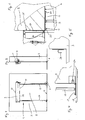
- a construction site door 1 has a roller blind or door box 2, which is provided for attachment to a building wall 3 in the region of a door lintel 4 above a building wall door opening 5.
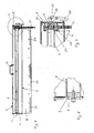
- the door box 2 is formed as a portable unit and has a winding shaft 6, which is rotatably mounted on both sides mounted end caps 7 and 8 by means of a respective bearing 9 and 10.
- a cover 11 is wound, the z. B. is formed by a windable tarpaulin, foil or a cover fabric and extends through a slot formed on the lower housing wall 12 of the otherwise closed Mattastens 2.
- the door box 2 is fixedly mounted on the outside of the building wall 3 above the lintel 4 of the building wall door opening 5 to be closed by means of an angle bracket 13.
- An upper or vertical leg 14 of the angle bracket 13 is fixedly connected to the rear wall 15 of the door base 2 and provided for application to the outside of the building wall 3, while a lower or horizontal leg 16 of the angle bracket 13 from below against the lintel 4 and attached thereto two vertical support units 17 is held taut, which is supported in the foot area on the floor or on the door frame 18.
- a respective bottom support plate 19 may be provided, the floor or door and / or on the building wall 3 z.
- B. is releasably attachable by anchoring and forms an intermediate layer or support for each support unit 17.
- the bottom bearing plate 19 can serve both for improved force absorption and force distribution as well as for attachment regardless of the nature and suitability of the floor or door frame 18.
- the angle bracket 13 and in particular its horizontal leg 16 may additionally z. B. by means of screw dowel fasteners 20 on the lintel 4. In this way, the door box 2 can be safely and stably mounted and fixed to the building wall 3.
- the width of the cover unit 11 is selected such that on both sides in each case an edge portion of the cover unit 11 covers the adjacent to the door opening 5 building wall 3, for example, about 3 to 10 cm.
- the width or length of the door box 2 is therefore slightly larger than the width of the cover unit 11. Nevertheless, the door box 2 is easily transportable and z. B. by means of a centrally mounted on the door box 2 carrying handle 21 also easy to carry by a person.
- the wound on the winding shaft 6 cover unit 11 or tarpaulin can be pulled on by pulling on their free pull-out edge 22 and adjusted in their the building door opening 5 covering the closed position.
- a plurality of elongated slot-like openings 23 are provided in the cover unit 11 or tarpaulin, by means of which the cover unit 11 or tarpaulin mounted near the bottom security parts 24 such.
- B. suspension hook can be hung.
- the winding shaft 6 can by a return spring (not shown), z.
- a return spring (not shown), z.
- a similar effect can also be achieved by spring steel inserts in the cover unit 11 or a fabric forming the cover unit.
- the winding shaft 6 can be fixed by means of a blocking device 25 against rotation.
- the blocking device 25 includes a clamping piece 26 which is arranged coaxially and rotationally fixed, but axially displaceable in the tubular winding shaft 6 in the region of the right housing-fixed bearing 10 and a screw 27th associated with, for example, an eccentric lever 28 which is pivotally mounted outside of the right end cover 8 and the screw 27 axially adjust the clamping piece 25 and can press to block the winding shaft 6 via an interposed serving as a friction brake intermediate ring 29 axially against the fixed bearing 10 ,
- the eccentric lever 28 can be secured against external actuation, for example by means of a padlock or the like, with which the eccentric lever 28 is fixed on or to the door box 2.
- a tensioning device for rotating the winding shaft 6, in particular for tensioning the cover unit 11 which has been pulled out and fastened to the securing parts 24, contains a toothed belt pulley 30 fastened to the outer circumference of the winding shaft 6, around which a toothed belt 31 is placed in the form of an endless loop. By manual pulling on the toothed belt 31, the winding shaft 6 can be adjusted either in both directions of rotation.
- the cover unit 11 or the fabric material is z. B. pulled by means of a pull-out edge 22 of the wound covering unit 11 handle down and hooked to the security parts 24.
- the winding shaft 6 is actuated by a ratchet or the like and thus biases the cover unit 11 or the fabric. If sufficient voltage is reached, can be connected via a lockable unit, for.
- a lockable ratchet a cultivated lockable cylinder lock or a ratchet with locking bolt, the winding shaft 6 are secured. In particular, this can also be a lockable window handle with ratchet attachment can be used.
- the two lateral edges of the cover unit 11 or tarpaulin can be guided in rails (not shown) which can be attached to the building wall 3 next to the door opening 5 and prevent unauthorized engagement behind the extended cover unit 11.
- door 1 in a further modified embodiment of the building site door 1 (see 11 to 18 ) contains the door box 2 at its rear wall 15 at least in a lower portion at least one outwardly open longitudinal groove 32, with which the door box 2 can be suspended from a projecting from the angle bracket 13 retaining lug 33 (see Fig. 12 ).
- An additional attachment, z. B. a screw with the angle bracket 13, may be provided if necessary.
- the two vertical support units 17 are z. B. adjustable to different lengths telescopic quick-release rods for one-man operation.
- the door box 2 contains z. B. in the region of the left bearing 9 of the winding shaft 6, a spring or flat spiral spring 34 which is attached on the one hand to the housing or the end cover 7 of the door latch 2 and on the other hand connected to the winding shaft 6 so that it exerts a retraction force on the winding shaft 6.
- a spring or flat spiral spring 34 which is attached on the one hand to the housing or the end cover 7 of the door latch 2 and on the other hand connected to the winding shaft 6 so that it exerts a retraction force on the winding shaft 6.
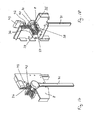
- the storage of the winding shaft 6 by means of a bearing element 35, which is connected to the right end cover 8 z. B. is firmly connected by rivets and part of a ratchet having locking mechanism 36 is.
- a bearing bush 38 is slidably mounted, which is bolted to a Mit Economicsflansch 39 which is firmly connected on one side to the winding shaft 6 and on the other hand connected to a polygonal or hexagonal profile 40 of the locking mechanism 36 and the ratchet and by means of a removable ratchet lever 41 is actuated or rotated.
- a locking bar 42 of the locking mechanism 36 is between a cocking or locking position (position as shown in FIGS FIGS. 17 and 18 ), in which the locking mechanism 36 is secured against rotation of its polygonal or hexagonal profile 40, and a neutral position in which the locking mechanism 36 is released and the polygonal or hexagonal profile 40 with the winding shaft 6 is rotatable.
- the locking bolt 42 of the locking mechanism 36 is locked by means of a padlock 43 or other security device in its blocking position (shown schematically).
- the door box 2 is suspended with its longitudinal groove 32 on the retaining lug 33 of the angle bracket 13.
- the locking bar 42 of the locking mechanism 36 is set in its neutral position (in Fig. 17 z. B. pivoted by 30 ° to the right), so that the cover unit 11 can be unwound from the winding shaft 6.
- the against the force of the flat coil spring 34 manually completely pulled cover unit 11 is suspended with the pull-out edge 22 in the safety hooks or securing parts 24.
- the locking bolt 42 is pivoted back into its blocking position, so that the locking mechanism 36, which also constitutes a tensioning device, prevents rotation of the winding shaft 6 in the stripping direction.
- the winding shaft 6 is rotated in the winding until the cover unit 11 is sufficiently strong.
- the locking bar 42 is secured with the padlock 43 and a securing device in its position and the ratchet lever 41 can be removed, so that an undesirable operation of the building site door 1 can be largely prevented in particular on an unguarded construction site.
- the door box 2 is biased on the tensioned cover unit 11 in the suspension on the retaining lug 33 and is thereby secured against unwanted removal.
- the winding shaft 6 is slightly further rotated in the tensioning or winding by means of possibly reattached lever, so that the locking bar 42 is relieved from the train of prestressed cover unit 11 and can be adjusted in its neutral position.
- the pull-out edge 22 of the cover unit 11 is pulled off the securing parts 24 and the cover unit 11 is wound up by the retraction force of the flat coil spring 34, while the pull-out edge 22 is guided manually upwards to the door box 2.
- the construction site door 1 according to the invention is thus easy to transport because it has no fixed and bulky U-shaped door frame compared to conventional construction site doors and manages without a solid and heavy door leaf.
- the door box 2 is comparatively small and the support units 17 can be transported independently of the door box 2.
- the cover unit 11 may be formed of a solid shock and puncture-proof fabric or such a film or has a much lower weight compared to a door leaf z. B. steel.
- construction site doors are merely exemplary embodiments and can be designed differently, in particular with regard to the tensioning and closing device.
Landscapes
- Engineering & Computer Science (AREA)
- Structural Engineering (AREA)
- Architecture (AREA)
- Civil Engineering (AREA)
- Operating, Guiding And Securing Of Roll- Type Closing Members (AREA)
- Extensible Doors And Revolving Doors (AREA)
Applications Claiming Priority (1)
| Application Number | Priority Date | Filing Date | Title |
|---|---|---|---|
| DE201210003891 DE102012003891A1 (de) | 2012-02-28 | 2012-02-28 | Baustellentür |
Publications (3)
| Publication Number | Publication Date |
|---|---|
| EP2634349A2 true EP2634349A2 (fr) | 2013-09-04 |
| EP2634349A3 EP2634349A3 (fr) | 2014-12-24 |
| EP2634349B1 EP2634349B1 (fr) | 2017-04-26 |
Family
ID=47900411
Family Applications (1)
| Application Number | Title | Priority Date | Filing Date |
|---|---|---|---|
| EP13000986.3A Not-in-force EP2634349B1 (fr) | 2012-02-28 | 2013-02-27 | Porte de chantier |
Country Status (3)
| Country | Link |
|---|---|
| EP (1) | EP2634349B1 (fr) |
| DE (1) | DE102012003891A1 (fr) |
| PL (1) | PL2634349T3 (fr) |
Families Citing this family (2)
| Publication number | Priority date | Publication date | Assignee | Title |
|---|---|---|---|---|
| DE102023135040B3 (de) | 2023-12-13 | 2025-01-23 | TFM Thermoform-Maschinen-Vertrieb GmbH | Einbruchschutz; Verfahren zum temporären Schutz einer Wandöffnung |
| FR3164498A1 (fr) * | 2024-07-11 | 2026-01-16 | Stéphanie Le Gall | Dispositif de cloisonnement d’urgence d’un passage, tel qu’un couloir ou une porte, et procédé de mise en œuvre. |
Citations (1)
| Publication number | Priority date | Publication date | Assignee | Title |
|---|---|---|---|---|
| DE29817064U1 (de) | 1998-09-23 | 1998-12-17 | Joh. Jos. Volberg GmbH & Co KG, 51469 Bergisch Gladbach | Ortsveränderliche Tür |
Family Cites Families (5)
| Publication number | Priority date | Publication date | Assignee | Title |
|---|---|---|---|---|
| DE8534960U1 (de) * | 1985-12-12 | 1986-03-06 | Farin, Erhard, 5463 Unkel | Vorrichtung zum Verschließen von Mauer- bzw. Fensteröffnungen |
| GB2409409B (en) * | 2003-11-18 | 2005-10-19 | * Hickey Stephen | Dust protection door |
| GB0801402D0 (en) * | 2008-01-25 | 2008-03-05 | Billington Structures Ltd | Shaft gate |
| AU2008201918A1 (en) * | 2008-05-01 | 2009-11-19 | Justin Montesalvo | An Improved Door |
| DE102010015005A1 (de) * | 2010-04-14 | 2012-05-10 | Heylo Drying Solutions Gmbh | Klemmeinheit für ein Türschott |
-
2012
- 2012-02-28 DE DE201210003891 patent/DE102012003891A1/de not_active Withdrawn
-
2013
- 2013-02-27 PL PL13000986T patent/PL2634349T3/pl unknown
- 2013-02-27 EP EP13000986.3A patent/EP2634349B1/fr not_active Not-in-force
Patent Citations (1)
| Publication number | Priority date | Publication date | Assignee | Title |
|---|---|---|---|---|
| DE29817064U1 (de) | 1998-09-23 | 1998-12-17 | Joh. Jos. Volberg GmbH & Co KG, 51469 Bergisch Gladbach | Ortsveränderliche Tür |
Also Published As
| Publication number | Publication date |
|---|---|
| EP2634349B1 (fr) | 2017-04-26 |
| EP2634349A3 (fr) | 2014-12-24 |
| DE102012003891A1 (de) | 2013-08-29 |
| PL2634349T3 (pl) | 2017-09-29 |
Similar Documents
| Publication | Publication Date | Title |
|---|---|---|
| EP2634349B1 (fr) | Porte de chantier | |
| EP2910511B1 (fr) | Cabine dotée d'un toit de protection réglable | |
| EP1908915B1 (fr) | Procédé de montage pour une porte à enroulement | |
| EP2789784B1 (fr) | Fermeture de bâtiment de type résistante aux explosions avec fixation de boucle de câble | |
| DE102008035767A1 (de) | Fahrzeugaufbau für Nutzfahrzeuge | |
| EP1302620A2 (fr) | Rouleau à ressort | |
| DE102014104868A1 (de) | Überdachung, insbesondere für ein Schwimmbad | |
| DE8525179U1 (de) | Vorrichtung zum Verhindern des Eindringens von Insekten in Räume | |
| AT501294B1 (de) | Insektenschutzvorrichtung | |
| DE102008035769C5 (de) | Fahrzeugaufbau für Nutzfahrzeuge | |
| DE102021113863A1 (de) | Schachtsicherungsvorrichtung | |
| DE3531476A1 (de) | Vorrichtung zum verhindern des eindringens von insekten in raeume | |
| DE4001461A1 (de) | Plane und vorrichtung zum aufrollen derselben | |
| DE102006050595B4 (de) | Verkleidung für einen Rollabschluss, insbesondere Rolltor oder ein Rollgitter, sowie damit versehene Rollabschlussvorrichtung | |
| DE102016109410B4 (de) | Mehrzweckständer | |
| DE4311416A1 (de) | Insektenschutz-Rollgittervorrichtung mit Einbruchsicherung | |
| DE102011103478A1 (de) | Rollobaugruppe mit einem Rollokasten, Haltebauteil zum Halten eines Rollokastens sowie Lagerschild | |
| DE19629619C2 (de) | Bewegliche Schutzwand | |
| DE2527382C3 (de) | Schutzabdeckung für verschwenkbare Dachflächenfenster | |
| DE202014101963U1 (de) | Flexible Trennwandanlage zum Verschließen einer Gebäudeöffnung | |
| EP3378821A1 (fr) | Dispositif de protection de personnes dans une cage d'ascenseur contre la chute éventuelle d'objets | |
| EP3444417B1 (fr) | Système de stockage pour ouvertures de bâtiment | |
| EP3002143B1 (fr) | Recouvrement lateral d'un chassis de vehicule utilitaire | |
| EP1764461A2 (fr) | Dispositif de verrouillage pour portes coulissantes | |
| DE19728908A1 (de) | Sonnenschutzeinrichtung für ein Fahrzeugfenster |
Legal Events
| Date | Code | Title | Description |
|---|---|---|---|
| PUAI | Public reference made under article 153(3) epc to a published international application that has entered the european phase |
Free format text: ORIGINAL CODE: 0009012 |
|
| AK | Designated contracting states |
Kind code of ref document: A2 Designated state(s): AL AT BE BG CH CY CZ DE DK EE ES FI FR GB GR HR HU IE IS IT LI LT LU LV MC MK MT NL NO PL PT RO RS SE SI SK SM TR |
|
| AX | Request for extension of the european patent |
Extension state: BA ME |
|
| PUAL | Search report despatched |
Free format text: ORIGINAL CODE: 0009013 |
|
| AK | Designated contracting states |
Kind code of ref document: A3 Designated state(s): AL AT BE BG CH CY CZ DE DK EE ES FI FR GB GR HR HU IE IS IT LI LT LU LV MC MK MT NL NO PL PT RO RS SE SI SK SM TR |
|
| AX | Request for extension of the european patent |
Extension state: BA ME |
|
| RIC1 | Information provided on ipc code assigned before grant |
Ipc: E04G 21/24 20060101ALI20141120BHEP Ipc: E06B 9/11 20060101ALI20141120BHEP Ipc: E06B 5/02 20060101AFI20141120BHEP |
|
| 17P | Request for examination filed |
Effective date: 20141218 |
|
| RBV | Designated contracting states (corrected) |
Designated state(s): AL AT BE BG CH CY CZ DE DK EE ES FI FR GB GR HR HU IE IS IT LI LT LU LV MC MK MT NL NO PL PT RO RS SE SI SK SM TR |
|
| 17Q | First examination report despatched |
Effective date: 20160229 |
|
| GRAP | Despatch of communication of intention to grant a patent |
Free format text: ORIGINAL CODE: EPIDOSNIGR1 |
|
| INTG | Intention to grant announced |
Effective date: 20161214 |
|
| GRAS | Grant fee paid |
Free format text: ORIGINAL CODE: EPIDOSNIGR3 |
|
| GRAA | (expected) grant |
Free format text: ORIGINAL CODE: 0009210 |
|
| AK | Designated contracting states |
Kind code of ref document: B1 Designated state(s): AL AT BE BG CH CY CZ DE DK EE ES FI FR GB GR HR HU IE IS IT LI LT LU LV MC MK MT NL NO PL PT RO RS SE SI SK SM TR |
|
| REG | Reference to a national code |
Ref country code: GB Ref legal event code: FG4D Free format text: NOT ENGLISH |
|
| REG | Reference to a national code |
Ref country code: CH Ref legal event code: EP |
|
| REG | Reference to a national code |
Ref country code: AT Ref legal event code: REF Ref document number: 888042 Country of ref document: AT Kind code of ref document: T Effective date: 20170515 |
|
| REG | Reference to a national code |
Ref country code: IE Ref legal event code: FG4D Free format text: LANGUAGE OF EP DOCUMENT: GERMAN |
|
| REG | Reference to a national code |
Ref country code: DE Ref legal event code: R096 Ref document number: 502013007050 Country of ref document: DE |
|
| REG | Reference to a national code |
Ref country code: NL Ref legal event code: MP Effective date: 20170426 |
|
| REG | Reference to a national code |
Ref country code: LT Ref legal event code: MG4D |
|
| PG25 | Lapsed in a contracting state [announced via postgrant information from national office to epo] |
Ref country code: NL Free format text: LAPSE BECAUSE OF FAILURE TO SUBMIT A TRANSLATION OF THE DESCRIPTION OR TO PAY THE FEE WITHIN THE PRESCRIBED TIME-LIMIT Effective date: 20170426 |
|
| PG25 | Lapsed in a contracting state [announced via postgrant information from national office to epo] |
Ref country code: ES Free format text: LAPSE BECAUSE OF FAILURE TO SUBMIT A TRANSLATION OF THE DESCRIPTION OR TO PAY THE FEE WITHIN THE PRESCRIBED TIME-LIMIT Effective date: 20170426 Ref country code: HR Free format text: LAPSE BECAUSE OF FAILURE TO SUBMIT A TRANSLATION OF THE DESCRIPTION OR TO PAY THE FEE WITHIN THE PRESCRIBED TIME-LIMIT Effective date: 20170426 Ref country code: LT Free format text: LAPSE BECAUSE OF FAILURE TO SUBMIT A TRANSLATION OF THE DESCRIPTION OR TO PAY THE FEE WITHIN THE PRESCRIBED TIME-LIMIT Effective date: 20170426 Ref country code: GR Free format text: LAPSE BECAUSE OF FAILURE TO SUBMIT A TRANSLATION OF THE DESCRIPTION OR TO PAY THE FEE WITHIN THE PRESCRIBED TIME-LIMIT Effective date: 20170727 Ref country code: NO Free format text: LAPSE BECAUSE OF FAILURE TO SUBMIT A TRANSLATION OF THE DESCRIPTION OR TO PAY THE FEE WITHIN THE PRESCRIBED TIME-LIMIT Effective date: 20170726 Ref country code: FI Free format text: LAPSE BECAUSE OF FAILURE TO SUBMIT A TRANSLATION OF THE DESCRIPTION OR TO PAY THE FEE WITHIN THE PRESCRIBED TIME-LIMIT Effective date: 20170426 |
|
| PG25 | Lapsed in a contracting state [announced via postgrant information from national office to epo] |
Ref country code: SE Free format text: LAPSE BECAUSE OF FAILURE TO SUBMIT A TRANSLATION OF THE DESCRIPTION OR TO PAY THE FEE WITHIN THE PRESCRIBED TIME-LIMIT Effective date: 20170426 Ref country code: RS Free format text: LAPSE BECAUSE OF FAILURE TO SUBMIT A TRANSLATION OF THE DESCRIPTION OR TO PAY THE FEE WITHIN THE PRESCRIBED TIME-LIMIT Effective date: 20170426 Ref country code: IS Free format text: LAPSE BECAUSE OF FAILURE TO SUBMIT A TRANSLATION OF THE DESCRIPTION OR TO PAY THE FEE WITHIN THE PRESCRIBED TIME-LIMIT Effective date: 20170826 Ref country code: LV Free format text: LAPSE BECAUSE OF FAILURE TO SUBMIT A TRANSLATION OF THE DESCRIPTION OR TO PAY THE FEE WITHIN THE PRESCRIBED TIME-LIMIT Effective date: 20170426 Ref country code: BG Free format text: LAPSE BECAUSE OF FAILURE TO SUBMIT A TRANSLATION OF THE DESCRIPTION OR TO PAY THE FEE WITHIN THE PRESCRIBED TIME-LIMIT Effective date: 20170726 |
|
| REG | Reference to a national code |
Ref country code: DE Ref legal event code: R097 Ref document number: 502013007050 Country of ref document: DE |
|
| PG25 | Lapsed in a contracting state [announced via postgrant information from national office to epo] |
Ref country code: DK Free format text: LAPSE BECAUSE OF FAILURE TO SUBMIT A TRANSLATION OF THE DESCRIPTION OR TO PAY THE FEE WITHIN THE PRESCRIBED TIME-LIMIT Effective date: 20170426 Ref country code: RO Free format text: LAPSE BECAUSE OF FAILURE TO SUBMIT A TRANSLATION OF THE DESCRIPTION OR TO PAY THE FEE WITHIN THE PRESCRIBED TIME-LIMIT Effective date: 20170426 Ref country code: EE Free format text: LAPSE BECAUSE OF FAILURE TO SUBMIT A TRANSLATION OF THE DESCRIPTION OR TO PAY THE FEE WITHIN THE PRESCRIBED TIME-LIMIT Effective date: 20170426 Ref country code: SK Free format text: LAPSE BECAUSE OF FAILURE TO SUBMIT A TRANSLATION OF THE DESCRIPTION OR TO PAY THE FEE WITHIN THE PRESCRIBED TIME-LIMIT Effective date: 20170426 Ref country code: CZ Free format text: LAPSE BECAUSE OF FAILURE TO SUBMIT A TRANSLATION OF THE DESCRIPTION OR TO PAY THE FEE WITHIN THE PRESCRIBED TIME-LIMIT Effective date: 20170426 |
|
| REG | Reference to a national code |
Ref country code: FR Ref legal event code: PLFP Year of fee payment: 6 |
|
| PG25 | Lapsed in a contracting state [announced via postgrant information from national office to epo] |
Ref country code: IT Free format text: LAPSE BECAUSE OF FAILURE TO SUBMIT A TRANSLATION OF THE DESCRIPTION OR TO PAY THE FEE WITHIN THE PRESCRIBED TIME-LIMIT Effective date: 20170426 Ref country code: SM Free format text: LAPSE BECAUSE OF FAILURE TO SUBMIT A TRANSLATION OF THE DESCRIPTION OR TO PAY THE FEE WITHIN THE PRESCRIBED TIME-LIMIT Effective date: 20170426 |
|
| PLBE | No opposition filed within time limit |
Free format text: ORIGINAL CODE: 0009261 |
|
| STAA | Information on the status of an ep patent application or granted ep patent |
Free format text: STATUS: NO OPPOSITION FILED WITHIN TIME LIMIT |
|
| 26N | No opposition filed |
Effective date: 20180129 |
|
| PG25 | Lapsed in a contracting state [announced via postgrant information from national office to epo] |
Ref country code: SI Free format text: LAPSE BECAUSE OF FAILURE TO SUBMIT A TRANSLATION OF THE DESCRIPTION OR TO PAY THE FEE WITHIN THE PRESCRIBED TIME-LIMIT Effective date: 20170426 |
|
| REG | Reference to a national code |
Ref country code: CH Ref legal event code: PL |
|
| PG25 | Lapsed in a contracting state [announced via postgrant information from national office to epo] |
Ref country code: MC Free format text: LAPSE BECAUSE OF FAILURE TO SUBMIT A TRANSLATION OF THE DESCRIPTION OR TO PAY THE FEE WITHIN THE PRESCRIBED TIME-LIMIT Effective date: 20170426 Ref country code: MT Free format text: LAPSE BECAUSE OF FAILURE TO SUBMIT A TRANSLATION OF THE DESCRIPTION OR TO PAY THE FEE WITHIN THE PRESCRIBED TIME-LIMIT Effective date: 20170426 |
|
| REG | Reference to a national code |
Ref country code: IE Ref legal event code: MM4A |
|
| REG | Reference to a national code |
Ref country code: BE Ref legal event code: MM Effective date: 20180228 |
|
| PG25 | Lapsed in a contracting state [announced via postgrant information from national office to epo] |
Ref country code: LI Free format text: LAPSE BECAUSE OF NON-PAYMENT OF DUE FEES Effective date: 20180228 Ref country code: LU Free format text: LAPSE BECAUSE OF NON-PAYMENT OF DUE FEES Effective date: 20180227 Ref country code: CH Free format text: LAPSE BECAUSE OF NON-PAYMENT OF DUE FEES Effective date: 20180228 |
|
| PG25 | Lapsed in a contracting state [announced via postgrant information from national office to epo] |
Ref country code: IE Free format text: LAPSE BECAUSE OF NON-PAYMENT OF DUE FEES Effective date: 20180227 |
|
| PG25 | Lapsed in a contracting state [announced via postgrant information from national office to epo] |
Ref country code: BE Free format text: LAPSE BECAUSE OF NON-PAYMENT OF DUE FEES Effective date: 20180228 |
|
| PG25 | Lapsed in a contracting state [announced via postgrant information from national office to epo] |
Ref country code: TR Free format text: LAPSE BECAUSE OF FAILURE TO SUBMIT A TRANSLATION OF THE DESCRIPTION OR TO PAY THE FEE WITHIN THE PRESCRIBED TIME-LIMIT Effective date: 20170426 |
|
| PG25 | Lapsed in a contracting state [announced via postgrant information from national office to epo] |
Ref country code: HU Free format text: LAPSE BECAUSE OF FAILURE TO SUBMIT A TRANSLATION OF THE DESCRIPTION OR TO PAY THE FEE WITHIN THE PRESCRIBED TIME-LIMIT; INVALID AB INITIO Effective date: 20130227 Ref country code: PT Free format text: LAPSE BECAUSE OF FAILURE TO SUBMIT A TRANSLATION OF THE DESCRIPTION OR TO PAY THE FEE WITHIN THE PRESCRIBED TIME-LIMIT Effective date: 20170426 |
|
| PG25 | Lapsed in a contracting state [announced via postgrant information from national office to epo] |
Ref country code: CY Free format text: LAPSE BECAUSE OF FAILURE TO SUBMIT A TRANSLATION OF THE DESCRIPTION OR TO PAY THE FEE WITHIN THE PRESCRIBED TIME-LIMIT Effective date: 20170426 Ref country code: MK Free format text: LAPSE BECAUSE OF NON-PAYMENT OF DUE FEES Effective date: 20170426 |
|
| PG25 | Lapsed in a contracting state [announced via postgrant information from national office to epo] |
Ref country code: AL Free format text: LAPSE BECAUSE OF FAILURE TO SUBMIT A TRANSLATION OF THE DESCRIPTION OR TO PAY THE FEE WITHIN THE PRESCRIBED TIME-LIMIT Effective date: 20170426 |
|
| PGFP | Annual fee paid to national office [announced via postgrant information from national office to epo] |
Ref country code: FR Payment date: 20210218 Year of fee payment: 9 |
|
| PGFP | Annual fee paid to national office [announced via postgrant information from national office to epo] |
Ref country code: DE Payment date: 20210223 Year of fee payment: 9 Ref country code: AT Payment date: 20210216 Year of fee payment: 9 Ref country code: GB Payment date: 20210215 Year of fee payment: 9 Ref country code: PL Payment date: 20210219 Year of fee payment: 9 |
|
| REG | Reference to a national code |
Ref country code: DE Ref legal event code: R119 Ref document number: 502013007050 Country of ref document: DE |
|
| REG | Reference to a national code |
Ref country code: AT Ref legal event code: MM01 Ref document number: 888042 Country of ref document: AT Kind code of ref document: T Effective date: 20220227 |
|
| GBPC | Gb: european patent ceased through non-payment of renewal fee |
Effective date: 20220227 |
|
| PG25 | Lapsed in a contracting state [announced via postgrant information from national office to epo] |
Ref country code: AT Free format text: LAPSE BECAUSE OF NON-PAYMENT OF DUE FEES Effective date: 20220227 |
|
| PG25 | Lapsed in a contracting state [announced via postgrant information from national office to epo] |
Ref country code: FR Free format text: LAPSE BECAUSE OF NON-PAYMENT OF DUE FEES Effective date: 20220228 |
|
| PG25 | Lapsed in a contracting state [announced via postgrant information from national office to epo] |
Ref country code: GB Free format text: LAPSE BECAUSE OF NON-PAYMENT OF DUE FEES Effective date: 20220227 Ref country code: DE Free format text: LAPSE BECAUSE OF NON-PAYMENT OF DUE FEES Effective date: 20220901 |
|
| PG25 | Lapsed in a contracting state [announced via postgrant information from national office to epo] |
Ref country code: PL Free format text: LAPSE BECAUSE OF NON-PAYMENT OF DUE FEES Effective date: 20220227 |