EP2634355A2 - Dispositif d'ombrage d'une ouverture de bâtiment et mécanisme d'inclinaison associé - Google Patents
Dispositif d'ombrage d'une ouverture de bâtiment et mécanisme d'inclinaison associé Download PDFInfo
- Publication number
- EP2634355A2 EP2634355A2 EP20130000910 EP13000910A EP2634355A2 EP 2634355 A2 EP2634355 A2 EP 2634355A2 EP 20130000910 EP20130000910 EP 20130000910 EP 13000910 A EP13000910 A EP 13000910A EP 2634355 A2 EP2634355 A2 EP 2634355A2
- Authority
- EP
- European Patent Office
- Prior art keywords
- housing
- reversing gear
- stop
- adjusting
- winding
- Prior art date
- Legal status (The legal status is an assumption and is not a legal conclusion. Google has not performed a legal analysis and makes no representation as to the accuracy of the status listed.)
- Granted
Links
Images

Classifications
-
- E—FIXED CONSTRUCTIONS
- E06—DOORS, WINDOWS, SHUTTERS, OR ROLLER BLINDS IN GENERAL; LADDERS
- E06B—FIXED OR MOVABLE CLOSURES FOR OPENINGS IN BUILDINGS, VEHICLES, FENCES OR LIKE ENCLOSURES IN GENERAL, e.g. DOORS, WINDOWS, BLINDS, GATES
- E06B9/00—Screening or protective devices for wall or similar openings, with or without operating or securing mechanisms; Closures of similar construction
- E06B9/24—Screens or other constructions affording protection against light, especially against sunshine; Similar screens for privacy or appearance; Slat blinds
- E06B9/26—Lamellar or like blinds, e.g. venetian blinds
- E06B9/28—Lamellar or like blinds, e.g. venetian blinds with horizontal lamellae, e.g. non-liftable
- E06B9/30—Lamellar or like blinds, e.g. venetian blinds with horizontal lamellae, e.g. non-liftable liftable
- E06B9/303—Lamellar or like blinds, e.g. venetian blinds with horizontal lamellae, e.g. non-liftable liftable with ladder-tape
- E06B9/307—Details of tilting bars and their operation
-
- E—FIXED CONSTRUCTIONS
- E06—DOORS, WINDOWS, SHUTTERS, OR ROLLER BLINDS IN GENERAL; LADDERS
- E06B—FIXED OR MOVABLE CLOSURES FOR OPENINGS IN BUILDINGS, VEHICLES, FENCES OR LIKE ENCLOSURES IN GENERAL, e.g. DOORS, WINDOWS, BLINDS, GATES
- E06B9/00—Screening or protective devices for wall or similar openings, with or without operating or securing mechanisms; Closures of similar construction
- E06B9/24—Screens or other constructions affording protection against light, especially against sunshine; Similar screens for privacy or appearance; Slat blinds
- E06B9/26—Lamellar or like blinds, e.g. venetian blinds
- E06B9/28—Lamellar or like blinds, e.g. venetian blinds with horizontal lamellae, e.g. non-liftable
- E06B9/30—Lamellar or like blinds, e.g. venetian blinds with horizontal lamellae, e.g. non-liftable liftable
- E06B9/303—Lamellar or like blinds, e.g. venetian blinds with horizontal lamellae, e.g. non-liftable liftable with ladder-tape
- E06B9/308—Lamellar or like blinds, e.g. venetian blinds with horizontal lamellae, e.g. non-liftable liftable with ladder-tape with coaxial tilting bar and raising shaft
-
- E—FIXED CONSTRUCTIONS
- E06—DOORS, WINDOWS, SHUTTERS, OR ROLLER BLINDS IN GENERAL; LADDERS
- E06B—FIXED OR MOVABLE CLOSURES FOR OPENINGS IN BUILDINGS, VEHICLES, FENCES OR LIKE ENCLOSURES IN GENERAL, e.g. DOORS, WINDOWS, BLINDS, GATES
- E06B9/00—Screening or protective devices for wall or similar openings, with or without operating or securing mechanisms; Closures of similar construction
- E06B9/24—Screens or other constructions affording protection against light, especially against sunshine; Similar screens for privacy or appearance; Slat blinds
- E06B9/26—Lamellar or like blinds, e.g. venetian blinds
- E06B9/28—Lamellar or like blinds, e.g. venetian blinds with horizontal lamellae, e.g. non-liftable
- E06B9/30—Lamellar or like blinds, e.g. venetian blinds with horizontal lamellae, e.g. non-liftable liftable
- E06B9/32—Operating, guiding, or securing devices therefor
- E06B9/322—Details of operating devices, e.g. pulleys, brakes, spring drums, drives
Definitions
- the invention relates to a building opening shading device, in particular a Venetian blind, according to the preamble of claim 13, and a reversing gear for a Venetian blind according to the preamble of claim 1.
- the winding shaft is usually on so-called reversing gear on building-side components, usually a header of the Venetian blind, stored.
- Generic reversing gears are manufactured for example by the companies Schüco and Hunter-Douglas.
- both the lifting straps extending through the drapery slats and acting on the lower end bar for turning on and off the external venetian blind hang, as do the turning tapes from the reversing gearboxes of the external venetian blind, which engage on the longitudinal edges of the drapery slats for pivoting or blinding the drapery slats.
- Reverse gearboxes of the generic type have for this purpose a housing provided with openings for passing through the winding shaft, in which a shaft sleeve which is normally pushed onto the winding shaft in a form-fitting manner is supported, whereby the winding shaft is rotatably fixed on the building side.
- the bearing sleeve is designed as a centric winding shaft receiving opening and a coil section having concentric winding for winding and unwinding a hanging down hanging with its one end fixable lift bands.
- each elevator belt passes through the slats of Raffstorebehangs and attacks on the lower end bar with its other, not attached to the winding portion of the reel end, so that the curtain by winding and unwinding of the Lift bands on the trained as a reel storage sleeve and can be drained.
- a reversing cord holder In the axial direction of the winding shaft next to the winding section while a reversing cord holder is housed in the reversing gear, usually coaxial with the reel or to the axis of rotation of the winding shaft to which the reversible tapes or turning tapes are attached.
- the reversible cord holder is connected via a clutch co-rotating with the reel, and by releasing the clutch relative to the reel rotatably.
- the spiral cord holder for example, be received in a ring on the side of the winding section coaxial with the winding shaft subsequent bearing neck.
- the coupling can then be realized via an annular spring surrounding the cylindrical bearing stub, which can be spread apart via its radially outwardly projecting ends projecting into the turn cord holder. If the spring is widened by pressure on one or both spring ends, the reversing cord holder can rotate relative to the reel.
- the reversible cord holder can for this purpose have two mutually circumferentially spaced, axially projecting wall sections, which are arranged between the two spring ends, so that depending on the direction of rotation of the reel one of the two wall sections presses on the spring end close to him, when the reversing cord holder is held on the rotational angle limiting arrangement.
- In the circumferential direction between the two spring ends may also be an axially projecting from the turncord holder driver over which the turncord holder with a by rotation of the reel on the spring and thus the approximately radially projecting spring ends transmitted torque is taken when the turncord holder is not prevented simultaneously from the rotational movement.
- generic reversing gear have a serving as a rotation angle limit stop arrangement, via which the rotation angle range is fixed, in which the turning cord holder is co-rotatively coupled to the reel, and over which the turning cord holder outside the rotation angle range is prevented from rotating. If the winding shaft is rotated to release the curtain in Entangablassraum, then the turning cord holder rotates first with the reel and the winding shaft until a Wendelkordelhalter deviser stop against a housing side stop runs and the turncord holder is thereby decoupled from the rotational movement in Behangablassoplasty and rotationally fixed to the housing.
- the slats of the blind reach a fully zujaloustechnisch position in which they are drained. After draining the blind with fully blind slats, it should be possible to rejoin the slats.
- the winding shaft is rotated in Behangaufzugides.
- a wendelkordelhalter deviser stop runs against a housing-side stop and the turncord holder is thereby disengaged from the rotational movement in Behangaufzugides and rotationally fixed to the housing.
- the rotation angle range thus corresponds to a rotational movement of the turn cord holder necessary for the raising and lowering of the slats when the curtain is completely lowered.
- the stop assembly may have two at the peripheral portions of the turning cord holder inside the housing provided stops, as well as a trained on Wendekordelhalter stop or counter stop, depending on Behang too on one or the other housing side stop runs, whereby the rotation angle range of Wendekordelhalters is limited to the peripheral region between the two housing-side stops, which is swept by the turncord holder side counter-stop.
- it can also be provided at two different peripheral portions on the turncord holder stops, which is circumferentially interposed a single stop on the housing, so that the rotation angle range of the turncord holder is limited to the peripheral region between the two Wendekordelhalter solutionen stops, the rotation of the turncord holder from the housing side counterstop is swept over.
- the Lüeinstell listening is, however, actuated from outside the housing.
- the position adjustment device can be actuated when the position adjustment device, stop arrangement, reversing cord holder and reel are installed in the reversing gear housing.
- To adjust the rotation angle range of the turning cord holder so neither the stop assembly, nor the Lüeinstellinnate, nor the other moving parts of the reversing gear need to be removed from the housing. Rather, an accessibility to the Lüeinstell sexual is provided, via which the desired rotation angle range can be specified in assembled or on the external blinds operable state of the reversing gear.
- Such a generic reverse gear is for example the font DE 600 17 006 T2 refer to.
- a concentrically arranged row of holes is provided in a side wall of the housing, wherein a pin is to be inserted through a selected hole which engages in a concentric groove on a recorded on the winding shaft disc, so that the choice of the hole in the the pin is inserted, the rotation angle range of the disc and thus the turning cord holder is adjusted.
- the pin thus serves as the building side fixed stop, which are associated with the ends of the concentric groove as counter-stops, wherein the position of the pin is set via the concentrically arranged series of holes.
- Another generic reversing gear shows the European patent application EP 2 211 012 A2 , wherein here, however, the holes extend almost closed annularly around the winding shaft around and two pins are provided, which form two building-fixed stops of the stop assembly.
- the invention provides access to the Heileinstell issued on the housing bottom, via which the Heileinstell annoying is accessible from the bottom with built-in external venetian blind and built-in reverse gear.
- the reversing gear are usually attached to a header, and serve as a bearing for a turn in the gearboxes or their reels rotatably recorded winding shaft on which a lamella existing curtain on at the bottom Lamella attacking and the other lamellae by cross-elevating belts is attached, which can be wound on a winding section of the reel or unwound from him, wherein further acting on the longitudinal sides of the Behanglamellen turning tapes are connected via the reversible cord strands with the turning cord holder of the reversing gear.
- the header usually a U-shaped profile, can be installed with downwardly opening U.
- each reversing gear is arranged with edge foot sections on the groove bottom of the U-profile standing.
- the groove bottom forming wall of the header can then have in the range of each reversing gear an opening through which the reversing gear is guided at least with its housing bottom or at least accessible.
- the Lüeinstell Marie is available for a below the usually mounted above a window or the like reversing fitter, so from below, in the installed state of the Venetian blind in both headliner mounting positions and in particular in the advantageous built-in U-profile headliner , So it can be readjusted, for example, after a test drive of Raffstorebehangs the rotation angle range of the turncord holder, without the reversing gear to be removed.
- An adjustment access opening may be provided on the housing bottom via which the Heileinstell issued from outside the housing is actuated.
- a tool such as a screwdriver through the Einstellzugriffsö réelle
- the position adjustment device has an actuating element, such as a lever, which is guided through the Einstellzugriffsö réelle and thus allows a tool-free adjustment of the rotation angle range.
- the position adjustment device could, for example, have a setting disk accommodated in the housing, on which one or more of the stops of the stop arrangement are formed, and on which a lever projecting in the radial direction through the setting access opening is further formed, via which the adjusting disk can be rotated.
- the Einstellzugriffsö réelle is advantageously provided on the housing bottom. If the Einstellzugriffsö réelle located in the bottom region of the side walls of the housing could possibly also be done so access from below on the HeileinstellISS, especially if the header, is installed with downwardly opening U.
- the Einstellzugriffsö réelle may, as mentioned above, be carried out relatively small for performing a screwdriver, in which case, however, the Lüeinstell Marie would have to be specially designed for operation on the screwdriver performed by the Einstellzugriffsö réelle.
- the inspection cover assembly may also simply have a rubber stopper with which the adjustment access opening is closed.
- a revision cover, a revision flap or other revision cover arrangement is also advantageously provided, with which the Einstellzugriffsö réelle is covered.
- the inspection cover assembly may, for example, have an access opening provided in the housing bottom Einstelleabriffsö réelle on the housing bottom or otherwise as from below releasably connected thereto inspection cover with which the Einstellzugriffsö réelle is covered.
- At least one of the stops of the stop arrangement on the removable inspection cover, for example as plug-in stop elements present therein, and thus to achieve the operability of the position adjustment device from outside the housing.
- a simple adjustment of the desired rotation angle range for the turncord holder even in the installed state of the outer blind and the reversing gear while good encapsulation of the reverse gear inside against weathering etc. and a stable structure of the reversing gear but it is a relatively small, for performing a tool such as, for example, to provide a screwdriver with a suitable adjustment access opening and to adjust the position adjustment device for actuation via the tool.
- the Lüeinstell in that at least one of Stops the stop assembly is formed on a movable from outside the housing actuator, which is mounted on a housing wall portion, preferably on the housing bottom.
- the adjusting element can advantageously be designed as a latch displaceably guided in a guide slot in the housing wall section.
- the Lüeinstell listening could have a rotatably received in the housing coaxially with the reel adjusting disc on which at least one of the stops of the stop assembly is provided, which is rotatable through the Einstellzugriffsö réelle therethrough, so that the position of the at least one stopper is adjustable, be it with an insertable through the Einstellzugriffsö réelle tool or with a movably received therein adjusting lever or the like.
- the adjusting disk For rotating the adjusting disk and thus for adjusting the position of the turntable attached to the turntable may preferably have at its outer periphery a number in this case radially inwardly recessed depressions, so for example as a gear grooves between radially outwardly projecting teeth.
- the adjusting disc can thus be rotated via a tool brought into engagement with one of the recesses, when the Einstellzugriffsö réelle and the area with the depressions on the adjusting disc are arranged to each other so that the adjusting disc or positional disk can be inserted through a through the Einstellzugriffö réelle, at a the wells attached, rod-shaped actuator, eg twist a screwdriver.
- an adjusting element displaceably mounted on the housing wall section is provided with a stop of the stop assembly or rotatably received in the housing adjusting disc with a stop the stop assembly, or both, after setting the position of the respective stop also a locking of the actuating element or the adjusting disc in the set position to be possible to ensure that the reversing cord holder is rotatably held on the housing via the stop assembly, if he wants to leave the set rotation angle range, that is, when he strikes with a turncord-side stop on a housing-side counter-stop of the stop assembly.
- the Lüeinstell Marie therefore has a locking device for the adjusting disk or the adjusting element on which or on which an adjustable stop is attached.
- a locking element that can be actuated from outside the housing can be provided as locking device, which locks on a housing wall section, in particular the housing bottom, between a locking position in which it locks the movable control element or the rotatable adjusting disk, and a release position in which it controls the movable actuating element or .
- the rotatable adjusting disk releases is movable and in particular displaceably mounted.
- the locking element may advantageously be formed analogously to the previously described adjusting element as a in a recessed in the housing bottom guide slot slidably guided latch.
- the locking element may be formed as in a recessed in the housing bottom guide slot slidably guided latch, which between its locking position in which it engages with its engaging portion in a set recess of the adjusting disc and thereby locks the adjusting disc, and a release position in which it is brought out of engagement with the recesses with its engagement portion and the adjusting disc thereby releases be formed.
- the bolt is captively received in the recessed in the bottom side housing wall guideway, for example provided on its walls of the guideway facing walls locking lugs, which in one of the locking position corresponding portion of the guideway wall and associated in one of the release position corresponding portion of the guideway wall corresponding recesses are, in which the locking element can snap into place after moving into the appropriate position.
- the locking element may have a T-shaped or dovetail-shaped guide portion, with which it is held in a correspondingly shaped guideway.
- the locking element for the adjusting disk and the adjusting member received on the housing side are formed with a stop of the stop assembly on a common component, a combined locking actuator, which thus a building-side stop the stop assembly and an engagement portion for locking the adjusting disc on its outer peripheral side Has depressions.
- the other building-side stop the stop assembly is then arranged on the adjusting disc.
- the locking element can, for example, be slidably received in a guide track in the housing base in the axial direction of the axis of rotation of the winding shaft and are in the locking position with its engagement portion in engagement with a set recess on the outer periphery of the adjusting disk, in which case the stop of the locking element simultaneously in one position in which it holds a counter-stopper formed on the turncord holder when the turncord holder is rotated.
- the position of the stop provided on the locking element in the circumferential direction is therefore not adjustable per se, however, the distance between the stop on the locking element and the stop on the rotatable adjusting disc, so that the rotation angle range in which the turning cord holder rotates with the reel, or enlarged can be reduced, the predetermined by the stop on the control element limit of the rotation angle range however, it remains invariable.
- a scale which is readable from outside the housing, preferably from below, is preferably provided, which reproduces the rotational angle range currently set via the position setting device.
- the scale can be advantageously applied to the land between the recesses of the adjusting disc, for example in the form of on the teeth of at least partially tooth-like adjusting disk applied numbers, of which always that through the Einstellzugriffsö réelle is read, which reflects the currently set rotation angle range.
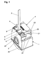
- the reversing gear has a housing 1 with a bottom-mounted inspection cover 4.
- the housing 1 has a cup-shaped lower part and a lid-shaped upper part, which are latched to each other via the upper part downwardly projecting locking projections 20 and their associated shoulders on the lower part.
- a reel 3 is housed and mounted on lateral openings of the housing through which a winding shaft can be guided, on which the reel 3 can be accommodated in a form-fitting manner.
- an elevator belt 2 hangs down, which in the mounted state of the Venetian blind, on which the reversing gear is installed, passes through the Behanglamellen and attacks on the lowermost Behanglamelle.
- the elevator belt 2 is guided by an elevator belt passage gap 8 in the lid 4.
- the cover 4 also has, for both sides in the normal direction to the axis of rotation of the winding shaft 8 für
- the lid 4 is thereby latched over two provided at its located in the normal direction to the axis of rotation flanks locking leg 22, each with a detent 23 on associated edge locking projections 21 on the housing bottom and additionally not shown, upwardly projecting retaining projections in undercut guideways 7 FIG. 2 ) held on the housing bottom 5.
- the housing 1 further has on its lower part in the near-bottom region edge-side foot portions 29 on which it can be arranged standing on the U-base in a U-shaped header with openings for the inspection cover 4, so that the inspection cover 4 from below for a mechanic is removable.
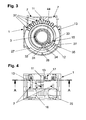
- FIG. 2 shows the reversing gear with the inspection cover removed 4.
- a lift tape access opening accessible, in which a lift belt revision insert 208 is inserted or used, on which the connected to a driver block 25 elevator belt 2 by a between two edge beads 205, 206 formed passage gap is added threaded.
- the Mitauerstein 25 fits into an associated driver exception on the winding section 16 of the reel 3 ( FIGS. 5 and 6 ) and can be wound up and unwound there by holding on the revision insert 208, semicircular guideway segments 214 and corresponding guideway segments on the upper part of the housing 1 the entrainment block 25 on the outer circumference of the winding section 16.
- the edge beads 205, 206 of the elevator band passage gap on the revision insert 208 are each attached via a spring leg 235, 236 at the bottom of Revisionscheschubs 208 and are spread when inserting the Revisionscheub 208 in the elevator tape access opening via associated Sp Dahldorne 19, so that the elevator belt 2 free - and unwind.
- the Revisionseinschubs 208 also has two edge-side locking legs 221, which each carry a locking lug 222, which point in the normal direction to the axis of rotation to the outside and can be engaged in corresponding locking exceptions on the elevator tape access opening.
- the latch 11 serves on the one hand as a detent for a in the Figures 3 . 5 and 6 To be taken, rotatably mounted in the housing 1 adjusting disc 13, and on the other hand has a building-side stop 36 of a stop assembly 34, 35, 36, via which a rotation angle range in which the reversing cord holder 14, 15 (FIGS. Figures 3 . 5 and 6 ) with the reel 3 rotates, given and limited, as will be explained in more detail below.
- the bolt is shown in its locking position in which he is with a on its upper side into the housing interior in the protruding portion in engagement with a located above the bolt 11 recess or groove 37 on the outer periphery of the adjusting disc 13, see FIG.
- the latch 11 If the latch 11 is moved over a screwdriver inserted into the slot 45 toward the elevator belt inspection opening, it passes into a release position and thus out of engagement with the recess 37 on the adjusting disk 13, so that the adjusting disk 13 can be rotated by means of the screwdriver inserted into the setting access opening 17 which engages there with a located above the Einstellzugriffsö Maschinen 17 recess 37 on the outer periphery of the adjusting disc 13.
- FIG. 4 shown plan view of the underside of the reversing gear with removed inspection cover 4 is shown, a number scale is applied to the outer periphery of the adjusting disc 13 at the areas between the grooves 37, which can be read through the Einstellzugriffsö réelle 17: It is a set rotational angle range reproducing Number visible, depending on which of the grooves 37 is located above the Einstellzugriffsö réelle 17.
- the guideway 10 has for the latch 11 on both sides inwardly projecting rail sections on which the latch 11 is guided captive.
- FIG. 4 the view into the elevator tape access opening freely, wherein in the FIG. 4 deviating from FIG. 2 the driver block 25 fastened at the end of the elevator belt 2 is drawn in its position accommodated on the winding section of the reel 3.
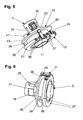
- FIGS. 5 and 6 show the "inner life" of the reversing gear shown in the other figures as a whole, so the recorded in the housing 1 components.
- the reel 3 with the winding portion 16 for winding and unwinding of the elevator belt 2, wherein the driving belt 25 mounted on the elevator end is already drawn in its recorded in the Mit Converseaus originallyung at the winding section 16 position.
- the reel 3 has a cylindrical bearing neck, on which the turning cord holder 14, 15 is received.
- the turning cord holder 14,15 has on its side facing the winding portion 16 a first annular disc 14 and on its side facing away from the winding portion 16, a second annular disc 15 and a cylindrical ring-shaped part 15.
- FIG. 5 and 6 show the "inner life" of the reversing gear shown in the other figures as a whole, so the recorded in the housing 1 components.
- an annular spring 12 is wrapped around the cylindrical bearing neck of the reel 3, the spring ends (in FIG. 3 is only a spring end 31 to recognize) in the radial direction in a defined between the two discs 14, 15 of the turn cord holder 14, 15 space.
- a driver 44 in the axial direction away from the winding portion in the space between the two spring ends 31 into, so that the first disc 14 at a rotation of the reel 3 is taken when one of the spring ends abuts the driver 44.
- the second annular disc 15 has an in FIG. 3 shown in section, annular cylindrical portion having an inner diameter which is larger than the spring ends protrude radially outward.
- Of the annular cylindrical portion of the second annular disc 15 are two the two annular spring ends 31 in the circumferential direction encompassing driver 32, 33 inwardly.
- the second disc 15 held against it so runs depending on the direction of rotation of the stops 32, 33 against the adjacent spring end 31 and thus expands the annular spring 12, so that the reel 3 can slip under the turn cord holder 14, 15, if this over the second annular disc 15 rotatably held on the housing.
- the two annular discs 14, 15 of the turn cord holder 14, 15 secured by a winding portion side ring portion 43 of the first annular disc 14 against a shoulder on the winding portion 16 and the cylinder ring portion of the second Ring disc 15 are pressed on the winding section 16 side facing away from a wall of the housing 1.
- the previously mentioned stop assembly 34, 35, 36 is provided, via which the turn cord holder 14, 15th outside the rotation angle range rotatably held on the housing 1.
- the two fixed stops 35, 36 are assigned.
- One of the two fixedly mounted on the housing side stops 35, 36 is provided on the latch 11, in extension of the inwardly projecting portion of the bolt 11 in the axial direction to the winding section 16 out.
- the other in the operating state of the gear drive housing fixed stop 35 is provided on the annular adjusting disk 13 as projecting in the axial direction to the winding portion 16 protruding projection and can be adjusted in its position in the circumferential direction on the adjusting disk 13.
Landscapes
- Engineering & Computer Science (AREA)
- Structural Engineering (AREA)
- Architecture (AREA)
- Civil Engineering (AREA)
- Blinds (AREA)
Applications Claiming Priority (1)
| Application Number | Priority Date | Filing Date | Title |
|---|---|---|---|
| DE201210003842 DE102012003842A1 (de) | 2012-02-29 | 2012-02-29 | Gebäudeöffnungsverschattungsvorrichtung und Wendegetriebe dafür |
Publications (3)
| Publication Number | Publication Date |
|---|---|
| EP2634355A2 true EP2634355A2 (fr) | 2013-09-04 |
| EP2634355A3 EP2634355A3 (fr) | 2014-08-20 |
| EP2634355B1 EP2634355B1 (fr) | 2015-10-14 |
Family
ID=47877688
Family Applications (1)
| Application Number | Title | Priority Date | Filing Date |
|---|---|---|---|
| EP13000910.3A Active EP2634355B1 (fr) | 2012-02-29 | 2013-02-22 | Dispositif d'ombrage d'une ouverture de bâtiment et mécanisme d'inclinaison associé |
Country Status (2)
| Country | Link |
|---|---|
| EP (1) | EP2634355B1 (fr) |
| DE (1) | DE102012003842A1 (fr) |
Citations (3)
| Publication number | Priority date | Publication date | Assignee | Title |
|---|---|---|---|---|
| US20040149399A1 (en) | 2002-12-30 | 2004-08-05 | Ober S.R.I. | Apparatus for adjusting the position of the slats of venetian blinds and venetian blind |
| DE60017006T2 (de) | 1999-05-11 | 2005-12-08 | Hunter Douglas Industries B.V. | Antrieb für eine Jalousie |
| EP2211012A2 (fr) | 2009-01-27 | 2010-07-28 | Franz Kraler | Dispositif d'entraînement et de déplacement pour les lamelles d'un store |
Family Cites Families (1)
| Publication number | Priority date | Publication date | Assignee | Title |
|---|---|---|---|---|
| DE10236869A1 (de) * | 2002-08-12 | 2004-02-26 | Warema Kunststofftechnik Und Maschinenbau Gmbh | Raffstore mit Wendelager |
-
2012
- 2012-02-29 DE DE201210003842 patent/DE102012003842A1/de not_active Ceased
-
2013
- 2013-02-22 EP EP13000910.3A patent/EP2634355B1/fr active Active
Patent Citations (3)
| Publication number | Priority date | Publication date | Assignee | Title |
|---|---|---|---|---|
| DE60017006T2 (de) | 1999-05-11 | 2005-12-08 | Hunter Douglas Industries B.V. | Antrieb für eine Jalousie |
| US20040149399A1 (en) | 2002-12-30 | 2004-08-05 | Ober S.R.I. | Apparatus for adjusting the position of the slats of venetian blinds and venetian blind |
| EP2211012A2 (fr) | 2009-01-27 | 2010-07-28 | Franz Kraler | Dispositif d'entraînement et de déplacement pour les lamelles d'un store |
Also Published As
| Publication number | Publication date |
|---|---|
| EP2634355A3 (fr) | 2014-08-20 |
| DE102012003842A1 (de) | 2013-08-29 |
| EP2634355B1 (fr) | 2015-10-14 |
Similar Documents
| Publication | Publication Date | Title |
|---|---|---|
| DE69822083T2 (de) | Betätigungsmechanismus für Abdeckungen von architektonischen Öffnungen | |
| EP2211012B1 (fr) | Dispositif d'entraînement et de déplacement pour les lamelles d'un store | |
| CH653090A5 (de) | Rafflamellenstore. | |
| DE3037759A1 (de) | Rafflamellenstore | |
| EP0050677B1 (fr) | Store vénitien | |
| CH650311A5 (de) | Rafflamellenstore. | |
| DE3037725A1 (de) | Rafflamellenstore | |
| EP2634355B1 (fr) | Dispositif d'ombrage d'une ouverture de bâtiment et mécanisme d'inclinaison associé | |
| EP2211011A2 (fr) | Dispositif d'entraînement et de déplacement pour les lamelles d'un store | |
| EP1839540A2 (fr) | Engrenage destiné au levage et à l'abaissement d'un rideau | |
| DE69701687T2 (de) | Faltjalousien für fenster und türen | |
| EP2343431B1 (fr) | Dispositif de réglage et procédé d'activation et de désactivation de la position de fonctionnement d'un store vénitien | |
| EP0684361A1 (fr) | Dispositif de levage et de pivotement pour stores à lamelles | |
| DE3037703A1 (de) | Rafflamellenstore mit an den lamellenenden angeordneten fuehrungsgliedern | |
| EP2634354B1 (fr) | Dispositif d'ombrage d'ouverture de bâtiment, dispositif à treuil et dispositif d'échange de courroie de hissage pour celui-ci | |
| EP3263825B1 (fr) | Store à lamelles | |
| EP1842464B1 (fr) | Dispositif destiné à plisser un rideau drapé avec un cordon unique | |
| EP2674564B1 (fr) | Store à lamelles et dispositif à treuil pour celui-ci | |
| DE2400643A1 (de) | Wendevorrichtung fuer lamellenraffstores | |
| DE19534970A1 (de) | Wendevorrichtung für eine raffbare Lamellen- oder Rolladenjalousie | |
| DE102012003844A1 (de) | Gebäudeöffnungsverschattungsvorrichtung und Wendegetriebe dafür | |
| EP0581005B1 (fr) | Rideau plissé | |
| DE10120998B4 (de) | Jalousie mit mindestens zwei Lamellensätzen | |
| EP1992778A2 (fr) | Dispositif de fin de course pour un store à lamelles | |
| EP2216477B1 (fr) | Couplage pour l'arbre d'enroulement d'un volet roulant |
Legal Events
| Date | Code | Title | Description |
|---|---|---|---|
| PUAI | Public reference made under article 153(3) epc to a published international application that has entered the european phase |
Free format text: ORIGINAL CODE: 0009012 |
|
| AK | Designated contracting states |
Kind code of ref document: A2 Designated state(s): AL AT BE BG CH CY CZ DE DK EE ES FI FR GB GR HR HU IE IS IT LI LT LU LV MC MK MT NL NO PL PT RO RS SE SI SK SM TR |
|
| AX | Request for extension of the european patent |
Extension state: BA ME |
|
| PUAL | Search report despatched |
Free format text: ORIGINAL CODE: 0009013 |
|
| AK | Designated contracting states |
Kind code of ref document: A3 Designated state(s): AL AT BE BG CH CY CZ DE DK EE ES FI FR GB GR HR HU IE IS IT LI LT LU LV MC MK MT NL NO PL PT RO RS SE SI SK SM TR |
|
| AX | Request for extension of the european patent |
Extension state: BA ME |
|
| RIC1 | Information provided on ipc code assigned before grant |
Ipc: E06B 9/322 20060101ALI20140714BHEP Ipc: E06B 9/307 20060101AFI20140714BHEP |
|
| 17P | Request for examination filed |
Effective date: 20150220 |
|
| RBV | Designated contracting states (corrected) |
Designated state(s): AL AT BE BG CH CY CZ DE DK EE ES FI FR GB GR HR HU IE IS IT LI LT LU LV MC MK MT NL NO PL PT RO RS SE SI SK SM TR |
|
| GRAP | Despatch of communication of intention to grant a patent |
Free format text: ORIGINAL CODE: EPIDOSNIGR1 |
|
| INTG | Intention to grant announced |
Effective date: 20150520 |
|
| GRAS | Grant fee paid |
Free format text: ORIGINAL CODE: EPIDOSNIGR3 |
|
| GRAA | (expected) grant |
Free format text: ORIGINAL CODE: 0009210 |
|
| AK | Designated contracting states |
Kind code of ref document: B1 Designated state(s): AL AT BE BG CH CY CZ DE DK EE ES FI FR GB GR HR HU IE IS IT LI LT LU LV MC MK MT NL NO PL PT RO RS SE SI SK SM TR |
|
| REG | Reference to a national code |
Ref country code: GB Ref legal event code: FG4D Free format text: NOT ENGLISH |
|
| REG | Reference to a national code |
Ref country code: AT Ref legal event code: REF Ref document number: 755237 Country of ref document: AT Kind code of ref document: T Effective date: 20151015 Ref country code: CH Ref legal event code: EP |
|
| REG | Reference to a national code |
Ref country code: NL Ref legal event code: MP Effective date: 20151014 |
|
| REG | Reference to a national code |
Ref country code: IE Ref legal event code: FG4D Free format text: LANGUAGE OF EP DOCUMENT: GERMAN |
|
| REG | Reference to a national code |
Ref country code: DE Ref legal event code: R096 Ref document number: 502013001300 Country of ref document: DE |
|
| REG | Reference to a national code |
Ref country code: FR Ref legal event code: PLFP Year of fee payment: 4 |
|
| REG | Reference to a national code |
Ref country code: LT Ref legal event code: MG4D |
|
| PG25 | Lapsed in a contracting state [announced via postgrant information from national office to epo] |
Ref country code: NL Free format text: LAPSE BECAUSE OF FAILURE TO SUBMIT A TRANSLATION OF THE DESCRIPTION OR TO PAY THE FEE WITHIN THE PRESCRIBED TIME-LIMIT Effective date: 20151014 Ref country code: IS Free format text: LAPSE BECAUSE OF FAILURE TO SUBMIT A TRANSLATION OF THE DESCRIPTION OR TO PAY THE FEE WITHIN THE PRESCRIBED TIME-LIMIT Effective date: 20160214 Ref country code: LT Free format text: LAPSE BECAUSE OF FAILURE TO SUBMIT A TRANSLATION OF THE DESCRIPTION OR TO PAY THE FEE WITHIN THE PRESCRIBED TIME-LIMIT Effective date: 20151014 Ref country code: ES Free format text: LAPSE BECAUSE OF FAILURE TO SUBMIT A TRANSLATION OF THE DESCRIPTION OR TO PAY THE FEE WITHIN THE PRESCRIBED TIME-LIMIT Effective date: 20151014 Ref country code: NO Free format text: LAPSE BECAUSE OF FAILURE TO SUBMIT A TRANSLATION OF THE DESCRIPTION OR TO PAY THE FEE WITHIN THE PRESCRIBED TIME-LIMIT Effective date: 20160114 Ref country code: IT Free format text: LAPSE BECAUSE OF FAILURE TO SUBMIT A TRANSLATION OF THE DESCRIPTION OR TO PAY THE FEE WITHIN THE PRESCRIBED TIME-LIMIT Effective date: 20151014 Ref country code: HR Free format text: LAPSE BECAUSE OF FAILURE TO SUBMIT A TRANSLATION OF THE DESCRIPTION OR TO PAY THE FEE WITHIN THE PRESCRIBED TIME-LIMIT Effective date: 20151014 |
|
| PG25 | Lapsed in a contracting state [announced via postgrant information from national office to epo] |
Ref country code: PL Free format text: LAPSE BECAUSE OF FAILURE TO SUBMIT A TRANSLATION OF THE DESCRIPTION OR TO PAY THE FEE WITHIN THE PRESCRIBED TIME-LIMIT Effective date: 20151014 Ref country code: BE Free format text: LAPSE BECAUSE OF NON-PAYMENT OF DUE FEES Effective date: 20160229 Ref country code: SE Free format text: LAPSE BECAUSE OF FAILURE TO SUBMIT A TRANSLATION OF THE DESCRIPTION OR TO PAY THE FEE WITHIN THE PRESCRIBED TIME-LIMIT Effective date: 20151014 Ref country code: RS Free format text: LAPSE BECAUSE OF FAILURE TO SUBMIT A TRANSLATION OF THE DESCRIPTION OR TO PAY THE FEE WITHIN THE PRESCRIBED TIME-LIMIT Effective date: 20151014 Ref country code: GR Free format text: LAPSE BECAUSE OF FAILURE TO SUBMIT A TRANSLATION OF THE DESCRIPTION OR TO PAY THE FEE WITHIN THE PRESCRIBED TIME-LIMIT Effective date: 20160115 Ref country code: PT Free format text: LAPSE BECAUSE OF FAILURE TO SUBMIT A TRANSLATION OF THE DESCRIPTION OR TO PAY THE FEE WITHIN THE PRESCRIBED TIME-LIMIT Effective date: 20160215 Ref country code: LV Free format text: LAPSE BECAUSE OF FAILURE TO SUBMIT A TRANSLATION OF THE DESCRIPTION OR TO PAY THE FEE WITHIN THE PRESCRIBED TIME-LIMIT Effective date: 20151014 Ref country code: FI Free format text: LAPSE BECAUSE OF FAILURE TO SUBMIT A TRANSLATION OF THE DESCRIPTION OR TO PAY THE FEE WITHIN THE PRESCRIBED TIME-LIMIT Effective date: 20151014 |
|
| REG | Reference to a national code |
Ref country code: DE Ref legal event code: R097 Ref document number: 502013001300 Country of ref document: DE |
|
| PG25 | Lapsed in a contracting state [announced via postgrant information from national office to epo] |
Ref country code: CZ Free format text: LAPSE BECAUSE OF FAILURE TO SUBMIT A TRANSLATION OF THE DESCRIPTION OR TO PAY THE FEE WITHIN THE PRESCRIBED TIME-LIMIT Effective date: 20151014 |
|
| PLBE | No opposition filed within time limit |
Free format text: ORIGINAL CODE: 0009261 |
|
| STAA | Information on the status of an ep patent application or granted ep patent |
Free format text: STATUS: NO OPPOSITION FILED WITHIN TIME LIMIT |
|
| PG25 | Lapsed in a contracting state [announced via postgrant information from national office to epo] |
Ref country code: RO Free format text: LAPSE BECAUSE OF FAILURE TO SUBMIT A TRANSLATION OF THE DESCRIPTION OR TO PAY THE FEE WITHIN THE PRESCRIBED TIME-LIMIT Effective date: 20151014 Ref country code: SM Free format text: LAPSE BECAUSE OF FAILURE TO SUBMIT A TRANSLATION OF THE DESCRIPTION OR TO PAY THE FEE WITHIN THE PRESCRIBED TIME-LIMIT Effective date: 20151014 Ref country code: EE Free format text: LAPSE BECAUSE OF FAILURE TO SUBMIT A TRANSLATION OF THE DESCRIPTION OR TO PAY THE FEE WITHIN THE PRESCRIBED TIME-LIMIT Effective date: 20151014 Ref country code: DK Free format text: LAPSE BECAUSE OF FAILURE TO SUBMIT A TRANSLATION OF THE DESCRIPTION OR TO PAY THE FEE WITHIN THE PRESCRIBED TIME-LIMIT Effective date: 20151014 Ref country code: SK Free format text: LAPSE BECAUSE OF FAILURE TO SUBMIT A TRANSLATION OF THE DESCRIPTION OR TO PAY THE FEE WITHIN THE PRESCRIBED TIME-LIMIT Effective date: 20151014 |
|
| 26N | No opposition filed |
Effective date: 20160715 |
|
| PG25 | Lapsed in a contracting state [announced via postgrant information from national office to epo] |
Ref country code: MC Free format text: LAPSE BECAUSE OF FAILURE TO SUBMIT A TRANSLATION OF THE DESCRIPTION OR TO PAY THE FEE WITHIN THE PRESCRIBED TIME-LIMIT Effective date: 20151014 Ref country code: LU Free format text: LAPSE BECAUSE OF FAILURE TO SUBMIT A TRANSLATION OF THE DESCRIPTION OR TO PAY THE FEE WITHIN THE PRESCRIBED TIME-LIMIT Effective date: 20160222 |
|
| PG25 | Lapsed in a contracting state [announced via postgrant information from national office to epo] |
Ref country code: SI Free format text: LAPSE BECAUSE OF FAILURE TO SUBMIT A TRANSLATION OF THE DESCRIPTION OR TO PAY THE FEE WITHIN THE PRESCRIBED TIME-LIMIT Effective date: 20151014 |
|
| REG | Reference to a national code |
Ref country code: IE Ref legal event code: MM4A |
|
| PG25 | Lapsed in a contracting state [announced via postgrant information from national office to epo] |
Ref country code: IE Free format text: LAPSE BECAUSE OF NON-PAYMENT OF DUE FEES Effective date: 20160222 |
|
| REG | Reference to a national code |
Ref country code: FR Ref legal event code: PLFP Year of fee payment: 5 |
|
| PG25 | Lapsed in a contracting state [announced via postgrant information from national office to epo] |
Ref country code: MT Free format text: LAPSE BECAUSE OF FAILURE TO SUBMIT A TRANSLATION OF THE DESCRIPTION OR TO PAY THE FEE WITHIN THE PRESCRIBED TIME-LIMIT Effective date: 20151014 |
|
| GBPC | Gb: european patent ceased through non-payment of renewal fee |
Effective date: 20170222 |
|
| REG | Reference to a national code |
Ref country code: FR Ref legal event code: PLFP Year of fee payment: 6 |
|
| PG25 | Lapsed in a contracting state [announced via postgrant information from national office to epo] |
Ref country code: GB Free format text: LAPSE BECAUSE OF NON-PAYMENT OF DUE FEES Effective date: 20170222 |
|
| PG25 | Lapsed in a contracting state [announced via postgrant information from national office to epo] |
Ref country code: CY Free format text: LAPSE BECAUSE OF FAILURE TO SUBMIT A TRANSLATION OF THE DESCRIPTION OR TO PAY THE FEE WITHIN THE PRESCRIBED TIME-LIMIT Effective date: 20151014 Ref country code: HU Free format text: LAPSE BECAUSE OF FAILURE TO SUBMIT A TRANSLATION OF THE DESCRIPTION OR TO PAY THE FEE WITHIN THE PRESCRIBED TIME-LIMIT; INVALID AB INITIO Effective date: 20130222 |
|
| PG25 | Lapsed in a contracting state [announced via postgrant information from national office to epo] |
Ref country code: TR Free format text: LAPSE BECAUSE OF FAILURE TO SUBMIT A TRANSLATION OF THE DESCRIPTION OR TO PAY THE FEE WITHIN THE PRESCRIBED TIME-LIMIT Effective date: 20151014 Ref country code: MK Free format text: LAPSE BECAUSE OF FAILURE TO SUBMIT A TRANSLATION OF THE DESCRIPTION OR TO PAY THE FEE WITHIN THE PRESCRIBED TIME-LIMIT Effective date: 20151014 |
|
| PG25 | Lapsed in a contracting state [announced via postgrant information from national office to epo] |
Ref country code: BG Free format text: LAPSE BECAUSE OF FAILURE TO SUBMIT A TRANSLATION OF THE DESCRIPTION OR TO PAY THE FEE WITHIN THE PRESCRIBED TIME-LIMIT Effective date: 20151014 |
|
| PG25 | Lapsed in a contracting state [announced via postgrant information from national office to epo] |
Ref country code: AL Free format text: LAPSE BECAUSE OF FAILURE TO SUBMIT A TRANSLATION OF THE DESCRIPTION OR TO PAY THE FEE WITHIN THE PRESCRIBED TIME-LIMIT Effective date: 20151014 |
|
| PGFP | Annual fee paid to national office [announced via postgrant information from national office to epo] |
Ref country code: FR Payment date: 20240221 Year of fee payment: 12 |
|
| PG25 | Lapsed in a contracting state [announced via postgrant information from national office to epo] |
Ref country code: FR Free format text: LAPSE BECAUSE OF NON-PAYMENT OF DUE FEES Effective date: 20250228 |
|
| REG | Reference to a national code |
Ref country code: CH Ref legal event code: U11 Free format text: ST27 STATUS EVENT CODE: U-0-0-U10-U11 (AS PROVIDED BY THE NATIONAL OFFICE) Effective date: 20260301 |
|
| PGFP | Annual fee paid to national office [announced via postgrant information from national office to epo] |
Ref country code: DE Payment date: 20260228 Year of fee payment: 14 |
|
| PGFP | Annual fee paid to national office [announced via postgrant information from national office to epo] |
Ref country code: AT Payment date: 20260216 Year of fee payment: 14 |
|
| PGFP | Annual fee paid to national office [announced via postgrant information from national office to epo] |
Ref country code: CH Payment date: 20260301 Year of fee payment: 14 |