EP2634863B1 - Bindung mit geringem elektrischen Widerstand - Google Patents
Bindung mit geringem elektrischen Widerstand Download PDFInfo
- Publication number
- EP2634863B1 EP2634863B1 EP13150150.4A EP13150150A EP2634863B1 EP 2634863 B1 EP2634863 B1 EP 2634863B1 EP 13150150 A EP13150150 A EP 13150150A EP 2634863 B1 EP2634863 B1 EP 2634863B1
- Authority
- EP
- European Patent Office
- Prior art keywords
- component
- low resistance
- resistance pathway
- flexible member
- sealant
- Prior art date
- Legal status (The legal status is an assumption and is not a legal conclusion. Google has not performed a legal analysis and makes no representation as to the accuracy of the status listed.)
- Active
Links
Images
Classifications
-
- H—ELECTRICITY
- H01—ELECTRIC ELEMENTS
- H01R—ELECTRICALLY-CONDUCTIVE CONNECTIONS; STRUCTURAL ASSOCIATIONS OF A PLURALITY OF MUTUALLY-INSULATED ELECTRICAL CONNECTING ELEMENTS; COUPLING DEVICES; CURRENT COLLECTORS
- H01R13/00—Details of coupling devices of the kinds covered by groups H01R12/70 or H01R24/00 - H01R33/00
- H01R13/46—Bases; Cases
- H01R13/52—Dustproof, splashproof, drip-proof, waterproof, or flameproof cases
- H01R13/5219—Sealing means between coupling parts, e.g. interfacial seal
-
- H—ELECTRICITY
- H01—ELECTRIC ELEMENTS
- H01R—ELECTRICALLY-CONDUCTIVE CONNECTIONS; STRUCTURAL ASSOCIATIONS OF A PLURALITY OF MUTUALLY-INSULATED ELECTRICAL CONNECTING ELEMENTS; COUPLING DEVICES; CURRENT COLLECTORS
- H01R4/00—Electrically-conductive connections between two or more conductive members in direct contact, i.e. touching one another; Means for effecting or maintaining such contact; Electrically-conductive connections having two or more spaced connecting locations for conductors and using contact members penetrating insulation
- H01R4/28—Clamped connections, spring connections
- H01R4/30—Clamped connections, spring connections utilising a screw or nut clamping member
- H01R4/34—Conductive members located under head of screw
-
- H—ELECTRICITY
- H01—ELECTRIC ELEMENTS
- H01R—ELECTRICALLY-CONDUCTIVE CONNECTIONS; STRUCTURAL ASSOCIATIONS OF A PLURALITY OF MUTUALLY-INSULATED ELECTRICAL CONNECTING ELEMENTS; COUPLING DEVICES; CURRENT COLLECTORS
- H01R13/00—Details of coupling devices of the kinds covered by groups H01R12/70 or H01R24/00 - H01R33/00
- H01R13/46—Bases; Cases
- H01R13/52—Dustproof, splashproof, drip-proof, waterproof, or flameproof cases
- H01R13/5216—Dustproof, splashproof, drip-proof, waterproof, or flameproof cases characterised by the sealing material, e.g. gels or resins
-
- H—ELECTRICITY
- H01—ELECTRIC ELEMENTS
- H01R—ELECTRICALLY-CONDUCTIVE CONNECTIONS; STRUCTURAL ASSOCIATIONS OF A PLURALITY OF MUTUALLY-INSULATED ELECTRICAL CONNECTING ELEMENTS; COUPLING DEVICES; CURRENT COLLECTORS
- H01R13/00—Details of coupling devices of the kinds covered by groups H01R12/70 or H01R24/00 - H01R33/00
- H01R13/648—Protective earth or shield arrangements on coupling devices, e.g. anti-static shielding
- H01R13/6485—Electrostatic discharge protection
-
- H—ELECTRICITY
- H01—ELECTRIC ELEMENTS
- H01R—ELECTRICALLY-CONDUCTIVE CONNECTIONS; STRUCTURAL ASSOCIATIONS OF A PLURALITY OF MUTUALLY-INSULATED ELECTRICAL CONNECTING ELEMENTS; COUPLING DEVICES; CURRENT COLLECTORS
- H01R13/00—Details of coupling devices of the kinds covered by groups H01R12/70 or H01R24/00 - H01R33/00
- H01R13/648—Protective earth or shield arrangements on coupling devices, e.g. anti-static shielding
- H01R13/658—High frequency shielding arrangements, e.g. against EMI [Electro-Magnetic Interference] or EMP [Electro-Magnetic Pulse]
-
- H—ELECTRICITY
- H01—ELECTRIC ELEMENTS
- H01R—ELECTRICALLY-CONDUCTIVE CONNECTIONS; STRUCTURAL ASSOCIATIONS OF A PLURALITY OF MUTUALLY-INSULATED ELECTRICAL CONNECTING ELEMENTS; COUPLING DEVICES; CURRENT COLLECTORS
- H01R4/00—Electrically-conductive connections between two or more conductive members in direct contact, i.e. touching one another; Means for effecting or maintaining such contact; Electrically-conductive connections having two or more spaced connecting locations for conductors and using contact members penetrating insulation
- H01R4/58—Electrically-conductive connections between two or more conductive members in direct contact, i.e. touching one another; Means for effecting or maintaining such contact; Electrically-conductive connections having two or more spaced connecting locations for conductors and using contact members penetrating insulation characterised by the form or material of the contacting members
- H01R4/64—Connections between or with conductive parts having primarily a non-electric function, e.g. frame, casing, rail
- H01R4/643—Connections between or with conductive parts having primarily a non-electric function, e.g. frame, casing, rail for rigid cylindrical bodies
Definitions
- the present invention relates generally to sealing components, and more particularly to the electrical bonding of components in a manner that provides for a low electrical resistance pathway between components utilizing only a localized portion of the components.
- Achieving a low resistance electrical bond provides protection for two classes of electromagnetic phenomena that can cause functional upsets in equipment, cause structural damage due to damage from concentrated energy absorption, or be potentially hazardous to personnel.
- Different regulatory requirements govern different equipment depending upon the application in which the equipment is used.
- two classes of electrical bonding are applicable to composite structures; Class R and Class S.
- Class R electrical bonding pertains to equipment containing electrical circuits which may produce radio frequencies, either desired or undesired, and requires that the equipment be designed such that a continuous low impedance bonding path is formed from the equipment, enclosure, or housing to an aircraft structure.
- Class R electrical bonding also requires that this be accomplished through clean metal-to-metal, prepared metal-to-composite, or composite-to-composite contact of mounting plates, racks, brackets, or other component mating surface(s).
- Class S electrical bonding applies to all conductive components of an aircraft that are subject to frictional charging and do not otherwise have a bonding requirements, and states that they shall be bonded to the aircraft structure with a total path resistance of 1 ohm or less.
- Class R electrical bonding states that the bonding paths shall be accomplished through mechanical contact of components and shall be configured to include the minimum number of interfaces consistent with accepted design practice for that type of equipment.
- one method of achieving the low resistance bonding requirement was to use the entire split line between interfacing components.
- a fillet of sealant was applied around the entire interface between the components and one or more bonding straps were attached to the assembled components to provide a path to ground.
- this method of achieving low resistance bonding added weight to the component assembly as a result of the sealant and fasteners used for the bonding strap(s).
- the method introduced complexity into the manufacture and repair of the components as the entire interface between the components was used to achieve a solid and durable bond.
- JP-2005 067421 discloses the electrical interconnection between a first and second component using a fastener.
- the low resistance pathway according to the invention is defined in claim 1 and includes a mounting flange that includes a flexible member, a surface interfacing the flexible member, a sealing feature, and a fastener.
- the sealing feature forms an interior edge of at least one of the flexible member and the surface.
- the fastener compresses the flexible member to contact the surface.
- the flexible member is of a reduced stiffness compared to another portion of the mounting flange.
- the present invention comprises a housing assembly as defined in claim 10.
- the invention includes a low resistance pathway comprising portions of a first component and a second component.
- Low resistance pathway includes a flexible member such as a tab, which is held in contact with an interface surface of the adjacent component by a fastener to achieve a low bonding resistance therebetween.
- a portion of low resistance pathway is isolated from the remainder of assembly by one or more sealing feature(s) such as a groove. The groove is filled with sealant along its length to create a seal between the bonding interface and the remainder of first and second components. Sealing feature(s) and sealant seal low resistance pathway from environmental factors that could cause corrosion which would increase the resistance of the low resistance pathway between the first and second components.
- Low resistance pathway is additionally sealed from the environment surrounding assembly using a fillet of sealant extending along the edge(s) of low resistance pathway.
- low resistance pathway provides a localized bonding interface with low resistance between first component and second component. Isolating the low resistance pathway to a localized portion of the first and second component reduces costs by eliminating the need for larger amounts of sealant and one or more fasteners for a bonding strap associated with the prior art. Additionally, low resistance pathway can reduce the costs associated with manufacture and repair of assembly.
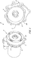
- FIG. 1 shows a perspective view of an assembly 10 with a split line 12 between a first component 14 and a second component 16.
- assembly 10 is disassembled to illustrate portions of assembly 10 including a mounting flange 18, apertures 20A and 20B, a sleeve 22, and a low resistance pathway 24.
- assembly 10 comprises a housing assembly for a component such as a motor, pump, or valve.
- a component such as a motor, pump, or valve.
- assembly 10 is disassembled along split line 12 to provide access to internal components (not shown).
- first component 14 has mounting flange 18 that extends circumferentially around first component 14 and projects radially outward therefrom.
- mounting flange 18 has multiple apertures 20A spaced therearound.
- Sleeve 22 extends from second component 16.
- Sleeve 22 extends circumferentially around second component 16 and projects axially outward therefrom.
- Sleeve 22 is sized to fit over the outer circumference of first component 14 when first component 14 and second component 16 are assembled.
- sleeve 22 has multiple apertures 20B spaced therearound.
- apertures 20A and 20B are aligned and receive fasteners (not shown) therein to secure first component 14 to second component 16.
- split line 12 comprises surfaces of mounting flange 18 and sleeve 22.
- a gasket or similar feature can be disposed along split line 12 to create a seal between first component 14 and second component 16.
- low resistance pathway 24 is segregated from the remainder of assembly 10 and comprises a small portion of mounting flange 18 and sleeve 22.
- low resistance pathway 24 takes up only a portion of assembly 10 and not the entire split line 12 as associated with the prior art.
- the size and number of bonding assemblies per component assembly will vary from embodiment to embodiment in order to achieve the desired resistance. Resistance of assembly 10 can be calculated utilizing commercially available software such as software available from ANSYS, Inc. of Canonsburg, Pennsylvania.
- low resistance pathway 24 By utilizing localized low resistance pathway 24, the weight and cost of the assembly 10 can be reduced by eliminating the need for larger amounts of sealant and one or more fasteners associated with the prior art. Additionally, low resistance pathway 24 can reduce the costs associated with manufacture and repair of assembly 10.
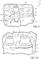
- FIGS. 2 and 2A show low resistance pathway 24 formed between the first components 14 and second component 16.
- FIG. 2 shows an exploded view of low resistance pathway 24 and FIG. 2A shows the application of a sealant 26 to parts of the low resistance pathway 24.
- low resistance pathway 24 includes a sealing feature 28 such as a groove, a tab 30, an interface surface 32, a tab fastener 34, a washer 36, and a fillet 38.
- FIG. 2A illustrates a split line fastener 40 in close proximity to low resistance pathway 24.
- Second component 16 has multiple apertures 20B spaced therearound. Similarly, first component 14 has multiple apertures 20A spaced therearound.
- apertures 20A and 20B are aligned and receive fasteners 40 therein to secure first component 14 to second component 16.
- low resistance pathway 24 is disposed at the outer circumference of assembly 10. In other embodiments, low resistance pathway 24 can be disposed at other locations along split line 12 such as an inner circumference.
- sealant 26 is disposed around the periphery of low resistance pathway 24 and is disposed in sealing feature 28. The amount (thickness, width, and height) of sealant 26 applied will vary with environment and application and should be sufficient to provide for a durable environmentally resistant bond. The type of sealant 26 can vary depending upon the application environment to which assembly 10 is exposed.
- sealant 26 comprises a fire resistant silicone sealant such as DAPCO® 2100 primerless silicone sealant manufactured by Cytec Industries Inc. of Woodland Park, New Jersey. DAPCO 2100 has fire resistance up to 3500°F (1925°C) and it has a fluid resistance to phosphate ester fluids.
- Sealing feature 28 comprises a machined groove that extends uninterrupted from a first edge of low resistance pathway 24 to a second edge of low resistance pathway 24. Sealing feature 28 allows sealant 26 to be disposed along an internal edge of low resistance pathway 24. As previously discussed sealing feature 28 is filled with sealant as shown in FIG. 2A to form a seal between low resistance pathway 24 and the remainder of assembly 10 and between the external environment and low resistance pathway 24. The size of sealing feature 28 will vary with environment and application and should be sufficient to provide for a durable environmentally resistant bond. Although shown as a single groove along second component 16, sealing feature 28 can comprise other structures capable of aiding to form a seal such as multiple grooves, tongue and groove, or the like. Sealing feature 28 can be disposed on first component 14, second component 16, or both first and second components 14 and 16 as desired.
- Tab 30 comprises a thin flexible member with reduced stiffness compared to other portions of mounting flange 18 ( FIG. 1 ). Thus, tab 30 deflects under the clamping force applied by tab fastener 34 to contact interface surface 32 of second component 16. By allowing tab 30 to flex under the clamping force applied by tab fastener 34, (through washer 36) flexible tab 30 allows the majority of the housing clamping pressure and vibration loads to be carried by split line fasteners 40 (only one is shown in FIGS. 2 and 2A ) connecting first component 14 to second component 16. Contact between tab 30 and interface surface 32 and between tab fastener 34 and second component 16 provides a low resistance pathway between first component 14 and second component 16.
- tab 30 has a smaller size than interface surface 32 such that interface surface 32 extends past the outer edge of tab 30 to form a ledge feature 37 between the tab 30 and interface surface 32 when first component 14 is mounted to second component 16.
- This ledge surface allows sealant 26 to be placed around the edge of tab 30 (and along the edge of interface surface 32) to form fillet 38.
- Fillet 38 of sealant 26 provides a durable seal from the environment surrounding assembly 10.
- fillet 38 and sealing feature 28 allow sealant 26 to be disposed entirely around tab fastener 34 to isolate tab fastener 34 from the remainder of assembly 10 and external environment.
Landscapes
- Gasket Seals (AREA)
- Vehicle Interior And Exterior Ornaments, Soundproofing, And Insulation (AREA)
Claims (11)
- Bindung mit geringem elektrischen Widerstand (24), umfassend:einen Befestigungsflansch (18) einer ersten Komponente (14), wobei der Befestigungsflansch (18) ein flexibles Element (30) beinhaltet;eine Fläche (32) einer zweiten Komponente (16), wobei die Fläche (32) mit dem flexiblen Element (30) verbunden ist;und gekennzeichnet durch ein Dichtungsmerkmal (28), das eine Innenkante von mindestens einem von dem flexiblen Element (30) und der Fläche (32) bildet; undeine Befestigung (34), die das flexible Element (30) zu elektrischem Kontakt mit der Fläche (32) komprimiert, und wobei das flexible Element (30) verglichen mit einem anderen Abschnitt des Befestigungsflansches (18) von reduzierter Steifigkeit ist.
- Bindung mit geringem elektrischen Widerstand (24) nach Anspruch 1, wobei das flexible Element (30) eine ablenkbare Lasche (30) umfasst, oder ferner umfassend ein Dichtungsmittel (26), das entlang des Dichtungsmerkmals (28) angeordnet ist, oder wobei das Dichtungsmerkmal (28) in einem Abstand zu der Befestigung (34) angeordnet ist und sich um einen Abschnitt davon herum erstreckt.
- Bindung mit geringem elektrischen Widerstand (24) nach Anspruch 1, wobei sich eine Größe des flexiblen Elements (30) von einer Größe der Fläche (32) unterscheidet, sodass dazwischen ein Vorsprung (37) gebildet ist.
- Bindung mit geringem elektrischen Widerstand (24) nach Anspruch 3, wobei ein Streifen eines Dichtungsmittels (26) zwischen dem flexiblen Element (30) und der Fläche (32) entlang des Vorsprungs (37) aufgetragen ist.
- Bindung mit geringem elektrischen Widerstand (24) nach Anspruch 1, wobei das Dichtungsmerkmal (28) eine Nut umfasst, die sich entlang der Fläche erstreckt.
- Bindung mit geringem elektrischen Widerstand (24) nach Anspruch 5, wobei die Nut im Wesentlichen mit einem Dichtungsmittel (26) gefüllt ist und wobei das Dichtungsmittel eine Fläche des flexiblen Elements kontaktiert.
- Bindung mit geringem elektrischen Widerstand nach Anspruch 1, wobei das flexible Element (30) einen Abschnitt der ersten Komponente (14) umfasst und die Fläche einen Abschnitt der zweiten Komponente (16) umfasst.
- Bindung mit geringem elektrischen Widerstand nach Anspruch 7, wobei die Fläche (32) einen Abschnitt einer geteilten Linie zwischen der ersten Komponente (14) und der zweiten Komponente (16) umfasst.
- Bindung mit geringem elektrischen Widerstand (24) nach Anspruch 7, wobei das Dichtungsmerkmal (28) und ein Dichtungsmittel (26) die Bindung mit geringem elektrischen Widerstand (24) abdichten, um die Bindung mit geringem elektrischen Widerstand (24) gegenüber dem Rest der ersten Komponente (14) und der zweiten Komponente (16) zu isolieren.
- Gehäusebaugruppe (10), umfassend:die erste Komponente (14); unddie zweite Komponente (16), wobei die erste Komponente (14) und die zweite Komponente (16) ausgelegt sind, um sich entlang einer geteilten Linie (12) zu verbinden; wobei die erste Komponente (14) und die zweite Komponente (16) zusammen die Bindung mit geringem elektrischen Widerstand (24) nach einem vorhergehenden Anspruch bilden, wobei die Bindung mit geringem elektrischen Widerstand (24) entlang eines Abschnitts der geteilten Linie (12) gebildet ist und wobei die Bindung mit geringem elektrischen Widerstand (24) gegenüber einem Rest der ersten Komponente (14) und der zweiten Komponente (16) abgedichtet ist und wobei die erste Komponente (14) den Befestigungsflansch (18) und das flexible Element (30) beinhaltet; die zweite Komponente (16) die Fläche (32) beinhaltet; und das Dichtungsmerkmal (28) eine Nut in der Fläche (32) der zweiten Komponente (16) beinhaltet, wobei die Nut die Innenkante der Fläche (32) bildet.
- Gehäusebaugruppe (10) nach Anspruch 10, wobei das flexible Element (30) eine ablenkbare Lasche umfasst.
Applications Claiming Priority (1)
| Application Number | Priority Date | Filing Date | Title |
|---|---|---|---|
| US13/408,081 US8816221B2 (en) | 2012-02-29 | 2012-02-29 | Low electrical resistance bond |
Publications (3)
| Publication Number | Publication Date |
|---|---|
| EP2634863A2 EP2634863A2 (de) | 2013-09-04 |
| EP2634863A3 EP2634863A3 (de) | 2013-11-27 |
| EP2634863B1 true EP2634863B1 (de) | 2018-05-23 |
Family
ID=47623912
Family Applications (1)
| Application Number | Title | Priority Date | Filing Date |
|---|---|---|---|
| EP13150150.4A Active EP2634863B1 (de) | 2012-02-29 | 2013-01-03 | Bindung mit geringem elektrischen Widerstand |
Country Status (2)
| Country | Link |
|---|---|
| US (1) | US8816221B2 (de) |
| EP (1) | EP2634863B1 (de) |
Family Cites Families (27)
| Publication number | Priority date | Publication date | Assignee | Title |
|---|---|---|---|---|
| US2250280A (en) * | 1940-05-14 | 1941-07-22 | Maurice M Starbird | Electrical bond |
| US2460181A (en) * | 1944-06-17 | 1949-01-25 | Pittsburgh Plate Glass Co | Sealing material |
| US3033582A (en) * | 1959-09-09 | 1962-05-08 | William G Creavey | Pressure actuated seal |
| US4175812A (en) | 1978-03-30 | 1979-11-27 | The United States Of America As Represented By The Secretary Of The Air Force | Electrically conductive bonding strap for connecting movable parts |
| US4597583A (en) * | 1985-07-08 | 1986-07-01 | Felt Products Mfg. Co. | Gasket assembly for sealing covers to automotive engines |
| US4813834A (en) * | 1985-08-01 | 1989-03-21 | Huck Manufacturing Company | Fit-up fastener with flexible tab-like retaining structure and method of making same |
| US4619275A (en) | 1985-08-05 | 1986-10-28 | Motorola, Inc. | Grounding ring |
| US4888451A (en) * | 1988-11-29 | 1989-12-19 | United Technologies Corporation | Electrical continuity means for composite joints |
| US5427386A (en) * | 1992-10-14 | 1995-06-27 | Corrosion Control Corp. | Protective seal for use in fluid flow lines and method therefor |
| US5349884A (en) * | 1993-10-28 | 1994-09-27 | Chrysler Corporation | Dust shield mounting system |
| US5749740A (en) | 1996-09-20 | 1998-05-12 | Hubbell Incorporated | Bonding strap for non-metallic electrical enclosure |
| US6119305A (en) * | 1997-06-17 | 2000-09-19 | Ta Mfg Co. | Sealing elements |
| US5859887A (en) | 1997-06-20 | 1999-01-12 | Westinghouse Electric Company | Nuclear fuel assembly support grid |
| JP3685915B2 (ja) | 1997-11-18 | 2005-08-24 | アスモ株式会社 | モータ装置 |
| JP3282588B2 (ja) | 1998-07-27 | 2002-05-13 | トヨタ自動車株式会社 | シールボルトによる導電性金属材料の接合構造 |
| US6543787B1 (en) * | 2001-03-28 | 2003-04-08 | Dana Corporation | Boundary gasket with waffle pattern sealing beads |
| JP4087315B2 (ja) | 2003-08-25 | 2008-05-21 | アスモ株式会社 | ケーシング構造及びモータ |
| GB0329891D0 (en) * | 2003-12-23 | 2004-01-28 | Airbus Uk Ltd | A sealing material |
| GB0417473D0 (en) | 2004-08-05 | 2004-09-08 | Airbus Uk Ltd | Fuel tank |
| DE102006022458B4 (de) | 2005-06-10 | 2019-08-08 | Schaeffler Technologies AG & Co. KG | Drehschwingungsdämpferscheibe und hydrodynamischer Drehmomentwandler mit einer Drehschwingungsdämpferscheibe |
| DE102006003160A1 (de) * | 2006-01-24 | 2007-09-06 | Airbus Deutschland Gmbh | Flächendichtung sowie Verfahren zur Herstellung von abgedichteten Fügeverbindungen mit der Flächendichtung |
| US20080116413A1 (en) | 2006-11-21 | 2008-05-22 | Honeywell International, Inc. | Pneumatic tube assembly for electrical bonding of pneumatic components |
| GB0704879D0 (en) | 2007-03-14 | 2007-04-18 | Rolls Royce Plc | A Casing arrangement |
| US20080237527A1 (en) | 2007-03-29 | 2008-10-02 | Honeywell International, Inc. | Valve assembly including a non-metallic valve flowbody and an esd bonding connection |
| ITRM20080185A1 (it) | 2008-04-09 | 2009-10-10 | Michele Cunico | Autoveicolo |
| JP5090273B2 (ja) | 2008-07-03 | 2012-12-05 | アスモ株式会社 | モータ |
| US20100019185A1 (en) | 2008-07-22 | 2010-01-28 | Honeywell International Inc. | Electrically conductive bonding means for device components |
-
2012
- 2012-02-29 US US13/408,081 patent/US8816221B2/en active Active
-
2013
- 2013-01-03 EP EP13150150.4A patent/EP2634863B1/de active Active
Non-Patent Citations (1)
| Title |
|---|
| None * |
Also Published As
| Publication number | Publication date |
|---|---|
| US20130220668A1 (en) | 2013-08-29 |
| EP2634863A3 (de) | 2013-11-27 |
| EP2634863A2 (de) | 2013-09-04 |
| US8816221B2 (en) | 2014-08-26 |
Similar Documents
| Publication | Publication Date | Title |
|---|---|---|
| CN102804535B (zh) | Emc防护压缩单元和包括该压缩单元的密封系统 | |
| US9609773B2 (en) | Isolator for an electronic device | |
| EP2412066B1 (de) | Elektrisch leitende lagerhalter | |
| US9343824B2 (en) | Sleeved fastener assembly | |
| EP2894358B1 (de) | Dichtungsscheibe | |
| US9291155B2 (en) | Vacuum pump motor and vacuum pump having balance rings | |
| CN102442434B (zh) | 雷击保护系统 | |
| EP2500272A2 (de) | Kupplungsstruktur für Luftrahmenkomponenten | |
| EP2836748B1 (de) | Duplexfingerdichtung für verbindungsstellen mit hoher relativer verschiebung | |
| EP2304298A2 (de) | Elektrische verindungsvorrichtung für eine ausziehbare flüssigkeitsleitungsanordnung | |
| KR20070109947A (ko) | 가스킷 | |
| EP2518340A1 (de) | Passflächen-Abdichtungsanwendung | |
| US20150357733A1 (en) | Low profile connector | |
| EP3296215A1 (de) | Montagemechanismus für hilfsgetriebe | |
| US7686344B2 (en) | Current insulation system for fluid systems | |
| EP2634863B1 (de) | Bindung mit geringem elektrischen Widerstand | |
| US9548144B2 (en) | Isolation system for an electronic device | |
| EP3514404A1 (de) | Hybrides bewegungsträgersystem | |
| EP2816268B1 (de) | Hochdruckrückschlagventilflanschverbindung | |
| EP3032929B1 (de) | Gehäuse für elektronische Steuereinheit | |
| CA2823744C (en) | Hermetic housing arrangement | |
| EP2938915B1 (de) | Dichtelement und -anordnung | |
| US20200194981A1 (en) | Electrical wire sealing assembly | |
| CN111520473A (zh) | 一种复合材料飞机油箱口盖密封结构及密封方法 | |
| EP4704260A1 (de) | Verbinderanordnung |
Legal Events
| Date | Code | Title | Description |
|---|---|---|---|
| PUAI | Public reference made under article 153(3) epc to a published international application that has entered the european phase |
Free format text: ORIGINAL CODE: 0009012 |
|
| AK | Designated contracting states |
Kind code of ref document: A2 Designated state(s): AL AT BE BG CH CY CZ DE DK EE ES FI FR GB GR HR HU IE IS IT LI LT LU LV MC MK MT NL NO PL PT RO RS SE SI SK SM TR |
|
| AX | Request for extension of the european patent |
Extension state: BA ME |
|
| PUAL | Search report despatched |
Free format text: ORIGINAL CODE: 0009013 |
|
| AK | Designated contracting states |
Kind code of ref document: A3 Designated state(s): AL AT BE BG CH CY CZ DE DK EE ES FI FR GB GR HR HU IE IS IT LI LT LU LV MC MK MT NL NO PL PT RO RS SE SI SK SM TR |
|
| AX | Request for extension of the european patent |
Extension state: BA ME |
|
| RIC1 | Information provided on ipc code assigned before grant |
Ipc: H01R 13/52 20060101ALI20131022BHEP Ipc: H01R 13/648 20060101ALN20131022BHEP Ipc: H01R 4/34 20060101AFI20131022BHEP Ipc: H05K 5/00 20060101ALN20131022BHEP |
|
| 17P | Request for examination filed |
Effective date: 20140526 |
|
| RBV | Designated contracting states (corrected) |
Designated state(s): AL AT BE BG CH CY CZ DE DK EE ES FI FR GB GR HR HU IE IS IT LI LT LU LV MC MK MT NL NO PL PT RO RS SE SI SK SM TR |
|
| STAA | Information on the status of an ep patent application or granted ep patent |
Free format text: STATUS: EXAMINATION IS IN PROGRESS |
|
| 17Q | First examination report despatched |
Effective date: 20161123 |
|
| RIC1 | Information provided on ipc code assigned before grant |
Ipc: H05K 5/00 20060101ALN20171006BHEP Ipc: H01R 13/52 20060101ALI20171006BHEP Ipc: H01R 4/34 20060101AFI20171006BHEP Ipc: H01R 13/648 20060101ALN20171006BHEP |
|
| GRAP | Despatch of communication of intention to grant a patent |
Free format text: ORIGINAL CODE: EPIDOSNIGR1 |
|
| STAA | Information on the status of an ep patent application or granted ep patent |
Free format text: STATUS: GRANT OF PATENT IS INTENDED |
|
| INTG | Intention to grant announced |
Effective date: 20171212 |
|
| GRAS | Grant fee paid |
Free format text: ORIGINAL CODE: EPIDOSNIGR3 |
|
| GRAA | (expected) grant |
Free format text: ORIGINAL CODE: 0009210 |
|
| STAA | Information on the status of an ep patent application or granted ep patent |
Free format text: STATUS: THE PATENT HAS BEEN GRANTED |
|
| AK | Designated contracting states |
Kind code of ref document: B1 Designated state(s): AL AT BE BG CH CY CZ DE DK EE ES FI FR GB GR HR HU IE IS IT LI LT LU LV MC MK MT NL NO PL PT RO RS SE SI SK SM TR |
|
| REG | Reference to a national code |
Ref country code: GB Ref legal event code: FG4D |
|
| REG | Reference to a national code |
Ref country code: CH Ref legal event code: EP |
|
| REG | Reference to a national code |
Ref country code: IE Ref legal event code: FG4D |
|
| REG | Reference to a national code |
Ref country code: AT Ref legal event code: REF Ref document number: 1002250 Country of ref document: AT Kind code of ref document: T Effective date: 20180615 |
|
| REG | Reference to a national code |
Ref country code: DE Ref legal event code: R096 Ref document number: 602013037711 Country of ref document: DE |
|
| REG | Reference to a national code |
Ref country code: NL Ref legal event code: MP Effective date: 20180523 |
|
| REG | Reference to a national code |
Ref country code: LT Ref legal event code: MG4D |
|
| PG25 | Lapsed in a contracting state [announced via postgrant information from national office to epo] |
Ref country code: BG Free format text: LAPSE BECAUSE OF FAILURE TO SUBMIT A TRANSLATION OF THE DESCRIPTION OR TO PAY THE FEE WITHIN THE PRESCRIBED TIME-LIMIT Effective date: 20180823 Ref country code: FI Free format text: LAPSE BECAUSE OF FAILURE TO SUBMIT A TRANSLATION OF THE DESCRIPTION OR TO PAY THE FEE WITHIN THE PRESCRIBED TIME-LIMIT Effective date: 20180523 Ref country code: NO Free format text: LAPSE BECAUSE OF FAILURE TO SUBMIT A TRANSLATION OF THE DESCRIPTION OR TO PAY THE FEE WITHIN THE PRESCRIBED TIME-LIMIT Effective date: 20180823 Ref country code: SE Free format text: LAPSE BECAUSE OF FAILURE TO SUBMIT A TRANSLATION OF THE DESCRIPTION OR TO PAY THE FEE WITHIN THE PRESCRIBED TIME-LIMIT Effective date: 20180523 Ref country code: LT Free format text: LAPSE BECAUSE OF FAILURE TO SUBMIT A TRANSLATION OF THE DESCRIPTION OR TO PAY THE FEE WITHIN THE PRESCRIBED TIME-LIMIT Effective date: 20180523 Ref country code: ES Free format text: LAPSE BECAUSE OF FAILURE TO SUBMIT A TRANSLATION OF THE DESCRIPTION OR TO PAY THE FEE WITHIN THE PRESCRIBED TIME-LIMIT Effective date: 20180523 |
|
| PG25 | Lapsed in a contracting state [announced via postgrant information from national office to epo] |
Ref country code: HR Free format text: LAPSE BECAUSE OF FAILURE TO SUBMIT A TRANSLATION OF THE DESCRIPTION OR TO PAY THE FEE WITHIN THE PRESCRIBED TIME-LIMIT Effective date: 20180523 Ref country code: NL Free format text: LAPSE BECAUSE OF FAILURE TO SUBMIT A TRANSLATION OF THE DESCRIPTION OR TO PAY THE FEE WITHIN THE PRESCRIBED TIME-LIMIT Effective date: 20180523 Ref country code: RS Free format text: LAPSE BECAUSE OF FAILURE TO SUBMIT A TRANSLATION OF THE DESCRIPTION OR TO PAY THE FEE WITHIN THE PRESCRIBED TIME-LIMIT Effective date: 20180523 Ref country code: GR Free format text: LAPSE BECAUSE OF FAILURE TO SUBMIT A TRANSLATION OF THE DESCRIPTION OR TO PAY THE FEE WITHIN THE PRESCRIBED TIME-LIMIT Effective date: 20180824 Ref country code: LV Free format text: LAPSE BECAUSE OF FAILURE TO SUBMIT A TRANSLATION OF THE DESCRIPTION OR TO PAY THE FEE WITHIN THE PRESCRIBED TIME-LIMIT Effective date: 20180523 |
|
| REG | Reference to a national code |
Ref country code: AT Ref legal event code: MK05 Ref document number: 1002250 Country of ref document: AT Kind code of ref document: T Effective date: 20180523 |
|
| PG25 | Lapsed in a contracting state [announced via postgrant information from national office to epo] |
Ref country code: RO Free format text: LAPSE BECAUSE OF FAILURE TO SUBMIT A TRANSLATION OF THE DESCRIPTION OR TO PAY THE FEE WITHIN THE PRESCRIBED TIME-LIMIT Effective date: 20180523 Ref country code: SK Free format text: LAPSE BECAUSE OF FAILURE TO SUBMIT A TRANSLATION OF THE DESCRIPTION OR TO PAY THE FEE WITHIN THE PRESCRIBED TIME-LIMIT Effective date: 20180523 Ref country code: EE Free format text: LAPSE BECAUSE OF FAILURE TO SUBMIT A TRANSLATION OF THE DESCRIPTION OR TO PAY THE FEE WITHIN THE PRESCRIBED TIME-LIMIT Effective date: 20180523 Ref country code: AT Free format text: LAPSE BECAUSE OF FAILURE TO SUBMIT A TRANSLATION OF THE DESCRIPTION OR TO PAY THE FEE WITHIN THE PRESCRIBED TIME-LIMIT Effective date: 20180523 Ref country code: DK Free format text: LAPSE BECAUSE OF FAILURE TO SUBMIT A TRANSLATION OF THE DESCRIPTION OR TO PAY THE FEE WITHIN THE PRESCRIBED TIME-LIMIT Effective date: 20180523 Ref country code: CZ Free format text: LAPSE BECAUSE OF FAILURE TO SUBMIT A TRANSLATION OF THE DESCRIPTION OR TO PAY THE FEE WITHIN THE PRESCRIBED TIME-LIMIT Effective date: 20180523 Ref country code: PL Free format text: LAPSE BECAUSE OF FAILURE TO SUBMIT A TRANSLATION OF THE DESCRIPTION OR TO PAY THE FEE WITHIN THE PRESCRIBED TIME-LIMIT Effective date: 20180523 |
|
| REG | Reference to a national code |
Ref country code: DE Ref legal event code: R097 Ref document number: 602013037711 Country of ref document: DE |
|
| PG25 | Lapsed in a contracting state [announced via postgrant information from national office to epo] |
Ref country code: SM Free format text: LAPSE BECAUSE OF FAILURE TO SUBMIT A TRANSLATION OF THE DESCRIPTION OR TO PAY THE FEE WITHIN THE PRESCRIBED TIME-LIMIT Effective date: 20180523 Ref country code: IT Free format text: LAPSE BECAUSE OF FAILURE TO SUBMIT A TRANSLATION OF THE DESCRIPTION OR TO PAY THE FEE WITHIN THE PRESCRIBED TIME-LIMIT Effective date: 20180523 |
|
| PLBE | No opposition filed within time limit |
Free format text: ORIGINAL CODE: 0009261 |
|
| STAA | Information on the status of an ep patent application or granted ep patent |
Free format text: STATUS: NO OPPOSITION FILED WITHIN TIME LIMIT |
|
| 26N | No opposition filed |
Effective date: 20190226 |
|
| PG25 | Lapsed in a contracting state [announced via postgrant information from national office to epo] |
Ref country code: SI Free format text: LAPSE BECAUSE OF FAILURE TO SUBMIT A TRANSLATION OF THE DESCRIPTION OR TO PAY THE FEE WITHIN THE PRESCRIBED TIME-LIMIT Effective date: 20180523 |
|
| REG | Reference to a national code |
Ref country code: DE Ref legal event code: R119 Ref document number: 602013037711 Country of ref document: DE |
|
| PG25 | Lapsed in a contracting state [announced via postgrant information from national office to epo] |
Ref country code: MC Free format text: LAPSE BECAUSE OF FAILURE TO SUBMIT A TRANSLATION OF THE DESCRIPTION OR TO PAY THE FEE WITHIN THE PRESCRIBED TIME-LIMIT Effective date: 20180523 |
|
| REG | Reference to a national code |
Ref country code: CH Ref legal event code: PL |
|
| PG25 | Lapsed in a contracting state [announced via postgrant information from national office to epo] |
Ref country code: LU Free format text: LAPSE BECAUSE OF NON-PAYMENT OF DUE FEES Effective date: 20190103 |
|
| REG | Reference to a national code |
Ref country code: BE Ref legal event code: MM Effective date: 20190131 |
|
| REG | Reference to a national code |
Ref country code: IE Ref legal event code: MM4A |
|
| PG25 | Lapsed in a contracting state [announced via postgrant information from national office to epo] |
Ref country code: DE Free format text: LAPSE BECAUSE OF NON-PAYMENT OF DUE FEES Effective date: 20190801 |
|
| PG25 | Lapsed in a contracting state [announced via postgrant information from national office to epo] |
Ref country code: AL Free format text: LAPSE BECAUSE OF FAILURE TO SUBMIT A TRANSLATION OF THE DESCRIPTION OR TO PAY THE FEE WITHIN THE PRESCRIBED TIME-LIMIT Effective date: 20180523 Ref country code: BE Free format text: LAPSE BECAUSE OF NON-PAYMENT OF DUE FEES Effective date: 20190131 |
|
| PG25 | Lapsed in a contracting state [announced via postgrant information from national office to epo] |
Ref country code: LI Free format text: LAPSE BECAUSE OF NON-PAYMENT OF DUE FEES Effective date: 20190131 Ref country code: CH Free format text: LAPSE BECAUSE OF NON-PAYMENT OF DUE FEES Effective date: 20190131 |
|
| PG25 | Lapsed in a contracting state [announced via postgrant information from national office to epo] |
Ref country code: IE Free format text: LAPSE BECAUSE OF NON-PAYMENT OF DUE FEES Effective date: 20190103 |
|
| PG25 | Lapsed in a contracting state [announced via postgrant information from national office to epo] |
Ref country code: TR Free format text: LAPSE BECAUSE OF FAILURE TO SUBMIT A TRANSLATION OF THE DESCRIPTION OR TO PAY THE FEE WITHIN THE PRESCRIBED TIME-LIMIT Effective date: 20180523 |
|
| PG25 | Lapsed in a contracting state [announced via postgrant information from national office to epo] |
Ref country code: MT Free format text: LAPSE BECAUSE OF NON-PAYMENT OF DUE FEES Effective date: 20190103 Ref country code: PT Free format text: LAPSE BECAUSE OF FAILURE TO SUBMIT A TRANSLATION OF THE DESCRIPTION OR TO PAY THE FEE WITHIN THE PRESCRIBED TIME-LIMIT Effective date: 20180924 |
|
| PG25 | Lapsed in a contracting state [announced via postgrant information from national office to epo] |
Ref country code: CY Free format text: LAPSE BECAUSE OF FAILURE TO SUBMIT A TRANSLATION OF THE DESCRIPTION OR TO PAY THE FEE WITHIN THE PRESCRIBED TIME-LIMIT Effective date: 20180523 |
|
| PG25 | Lapsed in a contracting state [announced via postgrant information from national office to epo] |
Ref country code: IS Free format text: LAPSE BECAUSE OF FAILURE TO SUBMIT A TRANSLATION OF THE DESCRIPTION OR TO PAY THE FEE WITHIN THE PRESCRIBED TIME-LIMIT Effective date: 20180923 |
|
| PG25 | Lapsed in a contracting state [announced via postgrant information from national office to epo] |
Ref country code: HU Free format text: LAPSE BECAUSE OF FAILURE TO SUBMIT A TRANSLATION OF THE DESCRIPTION OR TO PAY THE FEE WITHIN THE PRESCRIBED TIME-LIMIT; INVALID AB INITIO Effective date: 20130103 |
|
| PG25 | Lapsed in a contracting state [announced via postgrant information from national office to epo] |
Ref country code: MK Free format text: LAPSE BECAUSE OF FAILURE TO SUBMIT A TRANSLATION OF THE DESCRIPTION OR TO PAY THE FEE WITHIN THE PRESCRIBED TIME-LIMIT Effective date: 20180523 |
|
| P01 | Opt-out of the competence of the unified patent court (upc) registered |
Effective date: 20230522 |
|
| PGFP | Annual fee paid to national office [announced via postgrant information from national office to epo] |
Ref country code: GB Payment date: 20251219 Year of fee payment: 14 |
|
| PGFP | Annual fee paid to national office [announced via postgrant information from national office to epo] |
Ref country code: FR Payment date: 20251217 Year of fee payment: 14 |