EP2816268B1 - Hochdruckrückschlagventilflanschverbindung - Google Patents
Hochdruckrückschlagventilflanschverbindung Download PDFInfo
- Publication number
- EP2816268B1 EP2816268B1 EP14165361.8A EP14165361A EP2816268B1 EP 2816268 B1 EP2816268 B1 EP 2816268B1 EP 14165361 A EP14165361 A EP 14165361A EP 2816268 B1 EP2816268 B1 EP 2816268B1
- Authority
- EP
- European Patent Office
- Prior art keywords
- face
- valve flange
- mating portion
- tab
- flange
- Prior art date
- Legal status (The legal status is an assumption and is not a legal conclusion. Google has not performed a legal analysis and makes no representation as to the accuracy of the status listed.)
- Active
Links
Images
Classifications
-
- F—MECHANICAL ENGINEERING; LIGHTING; HEATING; WEAPONS; BLASTING
- F16—ENGINEERING ELEMENTS AND UNITS; GENERAL MEASURES FOR PRODUCING AND MAINTAINING EFFECTIVE FUNCTIONING OF MACHINES OR INSTALLATIONS; THERMAL INSULATION IN GENERAL
- F16K—VALVES; TAPS; COCKS; ACTUATING-FLOATS; DEVICES FOR VENTING OR AERATING
- F16K27/00—Construction of housing; Use of materials therefor
- F16K27/02—Construction of housing; Use of materials therefor of lift valves
- F16K27/0209—Check valves or pivoted valves
- F16K27/0227—Check valves or pivoted valves with the valve members swinging around an axis located at the edge of or outside the valve member
-
- F—MECHANICAL ENGINEERING; LIGHTING; HEATING; WEAPONS; BLASTING
- F16—ENGINEERING ELEMENTS AND UNITS; GENERAL MEASURES FOR PRODUCING AND MAINTAINING EFFECTIVE FUNCTIONING OF MACHINES OR INSTALLATIONS; THERMAL INSULATION IN GENERAL
- F16K—VALVES; TAPS; COCKS; ACTUATING-FLOATS; DEVICES FOR VENTING OR AERATING
- F16K15/00—Check valves
- F16K15/02—Check valves with guided rigid valve members
- F16K15/03—Check valves with guided rigid valve members with a hinged closure member or with a pivoted closure member
- F16K15/035—Check valves with guided rigid valve members with a hinged closure member or with a pivoted closure member with a plurality of valve members
- F16K15/036—Dual valve members with hinges crossing the flow line substantially diametrical
- F16K15/038—Dual valve members with hinges crossing the flow line substantially diametrical having a common hinge
-
- F—MECHANICAL ENGINEERING; LIGHTING; HEATING; WEAPONS; BLASTING
- F16—ENGINEERING ELEMENTS AND UNITS; GENERAL MEASURES FOR PRODUCING AND MAINTAINING EFFECTIVE FUNCTIONING OF MACHINES OR INSTALLATIONS; THERMAL INSULATION IN GENERAL
- F16L—PIPES; JOINTS OR FITTINGS FOR PIPES; SUPPORTS FOR PIPES, CABLES OR PROTECTIVE TUBING; MEANS FOR THERMAL INSULATION IN GENERAL
- F16L2201/00—Special arrangements for pipe couplings
- F16L2201/10—Indicators for correct coupling
-
- Y—GENERAL TAGGING OF NEW TECHNOLOGICAL DEVELOPMENTS; GENERAL TAGGING OF CROSS-SECTIONAL TECHNOLOGIES SPANNING OVER SEVERAL SECTIONS OF THE IPC; TECHNICAL SUBJECTS COVERED BY FORMER USPC CROSS-REFERENCE ART COLLECTIONS [XRACs] AND DIGESTS
- Y10—TECHNICAL SUBJECTS COVERED BY FORMER USPC
- Y10T—TECHNICAL SUBJECTS COVERED BY FORMER US CLASSIFICATION
- Y10T137/00—Fluid handling
- Y10T137/7504—Removable valve head and seat unit
-
- Y—GENERAL TAGGING OF NEW TECHNOLOGICAL DEVELOPMENTS; GENERAL TAGGING OF CROSS-SECTIONAL TECHNOLOGIES SPANNING OVER SEVERAL SECTIONS OF THE IPC; TECHNICAL SUBJECTS COVERED BY FORMER USPC CROSS-REFERENCE ART COLLECTIONS [XRACs] AND DIGESTS
- Y10—TECHNICAL SUBJECTS COVERED BY FORMER USPC
- Y10T—TECHNICAL SUBJECTS COVERED BY FORMER US CLASSIFICATION
- Y10T137/00—Fluid handling
- Y10T137/7722—Line condition change responsive valves
- Y10T137/7837—Direct response valves [i.e., check valve type]
-
- Y—GENERAL TAGGING OF NEW TECHNOLOGICAL DEVELOPMENTS; GENERAL TAGGING OF CROSS-SECTIONAL TECHNOLOGIES SPANNING OVER SEVERAL SECTIONS OF THE IPC; TECHNICAL SUBJECTS COVERED BY FORMER USPC CROSS-REFERENCE ART COLLECTIONS [XRACs] AND DIGESTS
- Y10—TECHNICAL SUBJECTS COVERED BY FORMER USPC
- Y10T—TECHNICAL SUBJECTS COVERED BY FORMER US CLASSIFICATION
- Y10T137/00—Fluid handling
- Y10T137/7722—Line condition change responsive valves
- Y10T137/7837—Direct response valves [i.e., check valve type]
- Y10T137/7854—In couplings for coaxial conduits, e.g., drill pipe check valves
-
- Y—GENERAL TAGGING OF NEW TECHNOLOGICAL DEVELOPMENTS; GENERAL TAGGING OF CROSS-SECTIONAL TECHNOLOGIES SPANNING OVER SEVERAL SECTIONS OF THE IPC; TECHNICAL SUBJECTS COVERED BY FORMER USPC CROSS-REFERENCE ART COLLECTIONS [XRACs] AND DIGESTS
- Y10—TECHNICAL SUBJECTS COVERED BY FORMER USPC
- Y10T—TECHNICAL SUBJECTS COVERED BY FORMER US CLASSIFICATION
- Y10T137/00—Fluid handling
- Y10T137/7722—Line condition change responsive valves
- Y10T137/7837—Direct response valves [i.e., check valve type]
- Y10T137/7854—In couplings for coaxial conduits, e.g., drill pipe check valves
- Y10T137/7857—Valve seat clamped between coupling elements
Definitions
- the present invention is related to check valves and in particular to check valve flange joints.
- Fluid check valves are known and commonly used in aircraft gas turbine engines. Check valves allow fluid to flow in only one direction, denying fluid flow in the opposite direction. Check valves may be utilized in harsh environments that include high fluid pressures and high temperatures. In these environments, the stresses placed on the mechanical parts of the check valve can be great. It is desirable to increase the strength of check valve parts for use in high pressure and high temperature environments.
- check valve It is also important to ensure that a check valve is properly installed. If installed backward, the check valve will block fluid flow in the desired direction, while allowing fluid flow in the undesired direction. This is important, for example, in applications that utilize check valves between high pressure components and low pressure components of a gas turbine engine. Because of this, safeguards that ensure proper installation of a check valve are desirable.
- valve flange joints comprising an annular valve flange which is mounted between annular first and second duct flanges.
- the invention provides a valve flange joint as set forth in claim 1.
- the invention provides a valve flange joint as set forth in claim 8.
- a flange joint for a check valve assembly is disclosed herein that includes two annular duct flanges and an annular check valve flange of similar thickness.
- a check valve for use in, for example, a gas turbine engine is oriented about a centerline.
- An annular check valve flange connected to the check valve is seated between first and second annular duct flanges.
- the outer profile of the duct flanges form a flange joint outer profile that may be, for example, defined with respect to an industry standard such as AS1895 which is an SAE Aerospace Standard defining the requirements for grooved clamp couplings, flanges, and seals suitable for joining high pressure and high temperature ducting in aircraft bleed air systems.
- Each duct flange includes a mating portion that extends radially outward from the centerline to mate with the check valve flange.
- Each mating portion includes a rim.
- the check valve flange includes an outer end that is radially inward of the mating portion rims.
- the mating portion rims interface to provide a tight clearance that pilots the check valve flange.
- the check valve flange includes an outer tab that ensures that the check valve is installed in the proper direction and proper position.
- the mating portion rims include slots for the check valve flange tab.
- the flange tab includes an inner surface that is radially inward of the outermost portion of the second duct flange. In this way, the check valve is only installable in one direction.
- the tab extends axially beyond hinges of an annular coupling, which provides visual indication that the check valve is installed.
- the first and second mating portions and the check valve flange are all of substantially equal thickness. This provides substantially equal strength for the three flanges. By providing equal strength for the three flanges, the check valve can perform better in high temperature and high pressure conditions such as, for example, approximately 1500 pounds per square inch gauge (psig) (10.342 MPa) and 1300 degrees Fahrenheit (704°C).
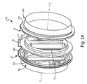
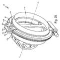
- FIGS. 1A and 1B are an exploded view and a perspective view of check valve assembly 10, respectively.
- Check valve assembly 10 is oriented annularly about centerline C L and includes check valve 12, which may be any known check valve.
- Check valve 12 includes check valve flange 14 which extends radially outward from centerline C L .
- Check valve assembly 10 further includes first and second duct flanges 16a and 16b.
- first and second duct flanges 16a and 16b may be, for example, outlet and inlet duct flanges, respectively.
- First and second duct flanges 16a and 16b include mating portions 17a and 17b. Mating portions 17a and 17b extend radially outward from centerline C L to mate with check valve flange 14.
- Check valve flange 14 includes tab 18 to ensure that check valve 12 is installed in the proper direction and position.
- Mating portions 17a and 17b include respective rims 20a and 20b.
- Rim 20a includes slot 22 to receive tab 18. Slot 22 does not extend through mating portion 17a.
- Rim 20b includes slot 23 to receive tab 18. Slot 23 extends through mating portion 17b to receive tab 18.
- Mating portions 17a and 17b along with check valve flange 14 form a flange joint.
- Coupling 24 (shown in FIG. 1B ) fits over the flange joint and is implemented to clamp check valve flange 14 (not visible in FIG. 1B ) between mating portions 17a and 17b.
- Coupling 24 includes hinges 25a and 25b. Hinge 25a includes hinge faces 26a and 27a. Hinge 25b includes hinge faces 26b and 27b. In an embodiment, coupling 24 may be implemented to conform with, for example, SAE industry standard AS1895.
- Tab 18 extends axially between and beyond hinge faces 27a and 27b of coupling 14 to provide a visual indication that check valve 12 is installed within check valve assembly 10. Hinge faces 27a and 27b may be, for example, coplanar. Tab 18 is also used to clock check valve 12 within check valve assembly 10. Because tab 18 interfaces with slots 22 and 23, check valve 12 is clocked to a single desired orientation within check valve assembly 10.
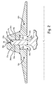
- FIG. 2 is a cross-sectional view of check valve flange 14 and duct flanges 16a and 16b taken at a point circumferentially offset from tab 18.
- Check valve flange 14 includes outer surface 28, and valve flange faces 30a and 30b.
- a thickness T 1 is defined as a minimum distance between faces 30a and 30b. In an embodiment, T 1 may be, for example, approximately 0.1 inches. By maintaining thickness T 1 for the entire radial length of flange 14, the strength of flange 14 is maximized.
- Duct flanges 16a and 16b include seal grooves 32a and 32b to receive seals (not shown).
- the seals are annular about center line C L and ensure that there is little to no fluid leakage at the interface between check valve flange 14 and duct flanges 16a and 16b.
- Flange mating portions 17a and 17b include faces 34a and 34b, and outer surfaces 36a and 36b, respectively.
- face 30a is in contact with face 34a
- face 30b is in contact with face 34b.
- Outer surface 28 is adjacent to the inner surfaces of rims 20a and 20b.
- the faces of rims 20a and 20b are adjacent to one another.
- the faces of rims 20a and 20b may provide a tight radial clearance for outer surface 28 to pilot check valve flange 14 into a proper position.
- Outer surfaces 36a and 36b may be substantially frustoconical in order to create a flange joint outer profile that conforms to, for example, SAE industry standard AS1895.
- Thickness T 2 is defined as a distance between outer surface 36a and shoulder 38a of seal groove 32a. This may be the minimum distance between shoulder 38a and outer surface 36a.
- Thickness T 3 is defined as a distance between outer surface 36b and shoulder 38b of seal groove 32b. This may be the minimum distance between shoulder 38b and outer surface 36b.
- Thicknesses T 1 , T 2 , and T 3 are substantially similar to maximize the distributed strength of each of the three flanges 14, 16a and 16b, respectively.
- a ratio between Thickness T 1 and T 2 may be, for example, between 0.8:1.0 and 1.2:1.0.
- a ratio between thicknesses T 1 and T 3 may be, for example, between 0.8:1.0 and 1.2:1.0.
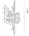
- FIG. 3 is a cross-sectional view of check valve flange 14 and duct flanges 16a and 16b taken through tab 18. Because of slot 22, face 34a of flange mating portion 17a extends to outer surface 40a and is in contact with face 30a of flange 14 and face 42 of tab 18 from seal groove 32a to outer surface 40a. Outer surface 40a is the outermost portion of mating portion 17a. Outer surface 40b is the base of slot 23 as shown in FIG. 1A and is radially inward from the outermost surface of flange mating portion 17b as shown in FIG. 2 .
- Tab 18 includes faces 42 and 44, inner surface 46 and outer surface 48.
- Face 42 is coplanar with face 30a of flange 14 and extends radially outward from face 30a to tab outer surface 48. Inner surface 46 is adjacent to surface 40b. Tab 18 extends axially from face 42 to face 44. Face 42 is axially between hinges 26a and 26b, and face 44 extends axially beyond hinge faces 27a and 27b of FIG. 1B .
- Tab 18 is utilized to ensure that check valve 12 of FIGS. 1A and 1B is installed in the proper direction and proper position.
- Inner surface 46 is radially inward of outermost surface 40a of duct flange 16a. Because the distance from centerline C L to outermost surface 40a is greater than the distance from centerline C L to inner surface 46 of tab 18, check valve 12 cannot be installed in the opposite direction. Further, because face 44 extends axially beyond hinge faces 27a and 27b, a visual indication is provided to indicate that check valve 12 is installed.
- Tab 18 also provides clocking for check valve 12. Because tab 18 interfaces with slots 22 and 23, check valve 12 can only be oriented in one position about centerline C L when installed. This way, tab 18 provides safeguards to prevent improper installation of check valve 12 while also providing indication that check valve 12 is installed.
Landscapes
- Engineering & Computer Science (AREA)
- General Engineering & Computer Science (AREA)
- Mechanical Engineering (AREA)
- Flanged Joints, Insulating Joints, And Other Joints (AREA)
- Check Valves (AREA)
- Valve Housings (AREA)
Claims (14)
- Ventilflanschverbindung, die um eine Mittellinie angeordnet ist, wobei die Ventilflanschverbindung Folgendes umfasst:einen ringförmigen Ventilflansch (14), der eine Lasche (18), eine erste Ventilflanschfläche (30 b) und eine zweite Ventilflanschfläche (30 a) einschließt;einen ersten ringförmigen Rohrflansch (16 b), der einen ersten Eingriffsabschnitt (17 b) einschließt, wobei der erste Eingriffsabschnitt (17 b) einen Rand (20 b), eine erste Rohrfläche (34 b), die sich in Kontakt mit der ersten Ventilflanschfläche (30 b) befindet, und einen ersten Schlitz (23), der sich durch den Rand (20 b) und den ersten Eingriffsabschnitt (17 b) erstreckt, einschließt; undeinen zweiten ringförmigen Rohrflansch (16 a), der einen zweiten Rohreingriffsabschnitt (17 a) einschließt, wobei der zweite Rohreingriffsabschnitt (17 a) eine Fläche (34 a), die sich in Kontakt mit der zweiten Ventilflanschfläche (30 a) befindet, und einen zweiten Rand (20 a) einschließt; unddadurch gekennzeichnet, dass die Lasche (18) sich in einer axialen Richtung durch den ersten Schlitz (23) erstreckt und wobei eine Innenfläche (46) der Lasche (18) radial einwärts von einem äußersten Abschnitt des zweiten Eingriffsabschnitts (17 a) liegt.
- Ventilflanschverbindung nach Anspruch 1, ferner umfassend:wobei eine erste Dicke (T1) als ein Mindestabstand zwischen der ersten Ventilflanschfläche (30 b) und der zweiten Ventilflanschfläche (30 a) definiert ist; undwobei der erste Eingriffsabschnitt (17 b) eine erste Außenfläche (36 b) und eine erste Nut (32 b) in der ersten Rohrfläche (34 b) einschließt und wobei eine zweite Dicke (T2) als ein Mindestabstand zwischen einer Schulter (38 b) der ersten Nut (38 b) und der ersten Außenfläche (36 b) definiert ist; undwobei der zweite Eingriffsabschnitt (17 a) eine zweite Außenfläche (36 a) und eine zweite Nut (32 a) in der zweiten Rohrfläche (34 a) einschließt und wobei eine dritte Dicke (T3) zwischen einer Schulter (38 a) der zweiten Nut (32 a) und der zweiten Außenfläche (36 a) definiert ist; und
wobei ein Verhältnis zwischen der ersten Dicke (T1) und der zweiten Dicke (T2) zwischen 0,8:1,0 und 1,2:1,0 liegt und ein Verhältnis zwischen der ersten Dicke (T1) und der dritten Dicke (T3) zwischen 0,8:1,0 und 1,2:1,0 liegt. - Ventilflanschverbindung nach Anspruch 1 oder 2, wobei sowohl eine oder die erste Außenfläche (36 b) des ersten Eingriffsabschnitts (17 b) als auch eine oder die zweite Außenfläche (36 a) des zweiten Eingriffsabschnitts (17 a) kegelstumpfförmig ist und wobei die erste Außenfläche (36 b) und die zweite Außenfläche (36 a) ein Flanschverbindungsaußenprofil bilden.
- Ventilflanschverbindung nach Anspruch 3, ferner umfassend eine ringförmige Verbindung (24), die eine Schnittstelle über dem Flanschverbindungsaußenprofil bildet, um den Ventilflansch (14) zwischen dem ersten Eingriffsabschnitt (17 b) und dem zweiten Eingriffsabschnitt (17 a) festzuklammern.
- Ventilflanschverbindung nach Anspruch 4, wobei die ringförmige Verbindung (24) erste und zweite Scharniere (25 a, 25 b) einschließt, wobei das erste Scharnier (25 a) eine erste Scharnierfläche (26 a) einschließt und wobei das zweite Scharnier (25 b) eine zweite Scharnierfläche (26 b) einschließt, die koplanar mit der ersten Scharnierfläche (26 a) ist, und wobei sich die Lasche (18) axial zwischen den ersten und zweiten Scharnieren (25 a, 25 b) über die ersten und zweiten Scharnierflächen (26 a, 26 b) hinaus erstreckt.
- Ventilflanschverbindung nach Anspruch 4 oder 5, wobei die Verbindung (24) die ersten und zweiten Eingriffsabschnitte (17 a, 17 b) nicht vollständig festklammert, wenn der Ventilflansch (14) nicht vorhanden ist.
- Ventilflanschverbindung nach einem der vorhergehenden Ansprüche, wobei der zweite Rand (20 a) einen zweiten Schlitz (22) einschließt und wobei sich eine erste Laschenfläche (42) durch den zweiten Schlitz (22) erstreckt und wobei die erste Laschenfläche (42) koplanar mit der zweiten Ventilflanschfläche (30 a) ist.
- Ventilflanschverbindung, umfassend:einen ringförmigen Ventilflansch (14), der um eine Mittellinie (CL) angeordnet ist und eine erste Ventilflanschfläche (30 b) und eine zweite Ventilflanschfläche (30 a) aufweist, wobei sich die ersten und zweiten Ventilflanschflächen (30 b, 30 a) in einer radialen Richtung senkrecht zu der Mittellinie (CL) erstrecken und eine erste Dicke (T1) als ein Mindestabstand zwischen der ersten Flanschfläche (30 b) und der zweiten Flanschfläche (30 a) definiert ist;einen ersten ringförmigen Rohrflansch (16 b), der um die Mittellinie (CL) angeordnet ist und einen ersten Eingriffsabschnitt (17 b) aufweist, wobei der erste Eingriffsabschnitt (17 b) eine erste Außenfläche (36 b) und eine erste Rohrfläche (34 b) einschließt, die sich in Kontakt mit der ersten Ventilflanschfläche (30 b) befindet, die sich zwischen einer ersten Dichtungsnut (32 b) und einem ersten Rand (20 b) erstreckt, und wobei eine zweite Dicke (T2) als der Mindestabstand zwischen einer Schulter (38 b) der ersten Dichtungsnut (32 b) und der ersten Außenfläche (36 b) definiert ist; undeinen zweiten ringförmigen Rohrflansch (16 a), der um die Mittellinie (CL) angeordnet ist und einen zweiten Eingriffsabschnitt (17 a) aufweist, wobei der zweite Eingriffsabschnitt (17 a) eine zweite Außenfläche (36 a) und eine zweite Rohrfläche (34 a) einschließt, die sich in Kontakt mit der zweiten Ventilflanschfläche (30 a) befindet, die sich zwischen einer zweiten Dichtungsnut (32 a) und einem zweiten Rand (20 a) erstreckt, und wobei eine dritte Dicke (T3) als der Mindestabstand zwischen einer Schulter (38 a) der zweiten Dichtungsnut (32 a) und der zweiten Außenfläche (36 a) definiert ist; undwobei ein Verhältnis zwischen der ersten Dicke (T1) und der zweiten Dicke (T2) zwischen 0,8:1,0 und 1,2:1,0 liegt und ein Verhältnis zwischen der ersten Dicke (T1) und der dritten Dicke (T3) zwischen 0,8:1,0 und 1,2:1,0 liegt; und
dadurch gekennzeichnet, dass der Ventilflansch (14) ferner eine Lasche (18) einschließt, wobei die Lasche (18) eine Innenfläche (46) parallel zu der Mittellinie (CL) umfasst, die radial einwärts von einem radial äußersten Abschnitt des zweiten Eingriffsabschnitts (17 a) liegt. - Ventilflanschverbindung nach Anspruch 8, wobei sowohl die erste Außenfläche (36 b) als auch die zweite Außenfläche (36 a) kegelstumpfförmig ist und wobei die erste Außenfläche (36 b) und die zweite Außenfläche (36 a) ein Flanschverbindungsaußenprofil bilden.
- Ventilflanschverbindung nach Anspruch 9, ferner umfassend eine ringförmige Verbindung (24), die eine Schnittstelle über dem Flanschverbindungsaußenprofil bildet, um den Ventilflansch (14) zwischen dem ersten Eingriffsabschnitt (17 b) und dem zweiten Eingriffsabschnitt (17 a) festzuklammern.
- Ventilflanschverbindung nach Anspruch 10, wobei die Verbindung (24) die ersten und zweiten Eingriffsabschnitte (17 b, 17 a) nicht vollständig festklammert, wenn der Ventilflansch (14) nicht vorhanden ist.
- Ventilflanschverbindung nach einem der Ansprüche 8 bis 11, wobei die ringförmige Verbindung (24) ein erstes Scharnier (25 a) und ein zweites Scharnier (25 b) einschließt, wobei das erste Scharnier (25 a) eine erste Scharnierfläche (26 a) einschließt und wobei das zweite Scharnier (25 b) eine zweite Scharnierfläche (26 b) einschließt, die koplanar mit der ersten Scharnierfläche (26 a) ist, und wobei sich die Lasche (18) axial über die ersten und zweiten Scharnierflächen (26 a, 26 b) hinaus erstreckt.
- Ventilflanschverbindung nach einem der Ansprüche 8 bis 12, wobei der erste Eingriffsabschnitt (17 b) einen ersten Schlitz (23) einschließt und wobei sich die Lasche (18) axial durch den ersten Schlitz (23) erstreckt.
- Ventilflanschverbindung nach einem der Ansprüche 8 bis 13, wobei der zweite Rand (20 a) einen zweiten Schlitz (22) einschließt und wobei sich eine Laschenfläche (42) der Lasche (18) radial durch den zweiten Schlitz (22) erstreckt und wobei die Laschenfläche (42) koplanar mit der zweiten Ventilflanschfläche (30 a) ist.
Applications Claiming Priority (1)
| Application Number | Priority Date | Filing Date | Title |
|---|---|---|---|
| US13/920,586 US9212756B2 (en) | 2013-06-18 | 2013-06-18 | High pressure check valve flange joint |
Publications (3)
| Publication Number | Publication Date |
|---|---|
| EP2816268A2 EP2816268A2 (de) | 2014-12-24 |
| EP2816268A3 EP2816268A3 (de) | 2015-07-08 |
| EP2816268B1 true EP2816268B1 (de) | 2016-11-02 |
Family
ID=50513107
Family Applications (1)
| Application Number | Title | Priority Date | Filing Date |
|---|---|---|---|
| EP14165361.8A Active EP2816268B1 (de) | 2013-06-18 | 2014-04-22 | Hochdruckrückschlagventilflanschverbindung |
Country Status (2)
| Country | Link |
|---|---|
| US (1) | US9212756B2 (de) |
| EP (1) | EP2816268B1 (de) |
Families Citing this family (5)
| Publication number | Priority date | Publication date | Assignee | Title |
|---|---|---|---|---|
| US20160208939A1 (en) * | 2015-01-20 | 2016-07-21 | United Technologies Corporation | Check valve with clocking and orientation features |
| US10077747B2 (en) | 2016-01-12 | 2018-09-18 | Hamilton Sundstrand Corporation | Fuel control system |
| EP3904819B1 (de) | 2020-04-27 | 2023-09-27 | Hamilton Sundstrand Corporation | Mit einem integrierten flansch unter verwendung eines generativen metallverfahrens gefertigter wärmetauscherkopf |
| US12535140B2 (en) * | 2023-05-17 | 2026-01-27 | Cornell Pump Company LLC | Replaceable seat for convertible check valve |
| USD1054942S1 (en) * | 2023-07-05 | 2024-12-24 | Shanghai Baidun Auto Parts Co., Ltd | Exhaust reducer assembly |
Family Cites Families (5)
| Publication number | Priority date | Publication date | Assignee | Title |
|---|---|---|---|---|
| US3884508A (en) * | 1973-12-10 | 1975-05-20 | Eugene G Jones | Pipe couplings |
| US4148338A (en) * | 1977-08-26 | 1979-04-10 | Mojonnier Bros. Co. | Check valve |
| US5368069A (en) | 1993-05-28 | 1994-11-29 | Eg&G Pressure Science, Inc. | Conduit joint assembly |
| CN102483170B (zh) | 2009-06-30 | 2014-03-26 | 伊顿公司 | 流体管道构造和流体止回阀组件 |
| US9157537B2 (en) | 2009-06-30 | 2015-10-13 | Eaton Corporation | Aircraft fluid check valve assembly with indexing |
-
2013
- 2013-06-18 US US13/920,586 patent/US9212756B2/en active Active
-
2014
- 2014-04-22 EP EP14165361.8A patent/EP2816268B1/de active Active
Also Published As
| Publication number | Publication date |
|---|---|
| US20140366966A1 (en) | 2014-12-18 |
| US9212756B2 (en) | 2015-12-15 |
| EP2816268A2 (de) | 2014-12-24 |
| EP2816268A3 (de) | 2015-07-08 |
Similar Documents
| Publication | Publication Date | Title |
|---|---|---|
| EP2816268B1 (de) | Hochdruckrückschlagventilflanschverbindung | |
| US9759079B2 (en) | Split line flow path seals | |
| US9074687B2 (en) | Sealing device for turbocharger | |
| EP3594549B1 (de) | Blocksitz und dichtungsstruktur | |
| US8225614B2 (en) | Shim for sealing transition pieces | |
| EP2900971B1 (de) | Aufhänger zur flexiblen verbindung mehrerer tafeln | |
| US9670791B2 (en) | Flexible finger seal for sealing a gap between turbine engine components | |
| US8490409B2 (en) | Bleed air transfer tube | |
| US20170218785A1 (en) | Turbomachine module | |
| US9829199B2 (en) | Flange with curved contact surface | |
| US10247031B2 (en) | Waveguide | |
| EP3608522B1 (de) | Turbolader | |
| CN103090117B (zh) | 一种穿过机匣的管路密封结构 | |
| JP7433740B2 (ja) | ガスタービンにおける角漏れ防止シール | |
| US8920113B2 (en) | Thermal gradiant tolerant turbomachine coupling member | |
| US9157537B2 (en) | Aircraft fluid check valve assembly with indexing | |
| US9551632B2 (en) | Probe retention-sealing feature | |
| CN103123025A (zh) | 一种允许轴向膨胀的高温管路密封结构 | |
| US20150137513A1 (en) | Keyed fitting | |
| EP4086496B1 (de) | Übertragungsrohranordnung | |
| EP3056682B1 (de) | Wärmebeweglicher beschlag für hochtemperaturrohranwendungen | |
| EP3754228A1 (de) | Luftdichtungsaufsatz | |
| EP3032147B1 (de) | "dog-bone" dichtung | |
| EP3293430B1 (de) | Gelenkige kupplungsanordnung | |
| US11022241B2 (en) | Device for limiting the loosening of a nut in a turbine engine |
Legal Events
| Date | Code | Title | Description |
|---|---|---|---|
| PUAI | Public reference made under article 153(3) epc to a published international application that has entered the european phase |
Free format text: ORIGINAL CODE: 0009012 |
|
| 17P | Request for examination filed |
Effective date: 20140422 |
|
| AK | Designated contracting states |
Kind code of ref document: A2 Designated state(s): AL AT BE BG CH CY CZ DE DK EE ES FI FR GB GR HR HU IE IS IT LI LT LU LV MC MK MT NL NO PL PT RO RS SE SI SK SM TR |
|
| AX | Request for extension of the european patent |
Extension state: BA ME |
|
| PUAL | Search report despatched |
Free format text: ORIGINAL CODE: 0009013 |
|
| AK | Designated contracting states |
Kind code of ref document: A3 Designated state(s): AL AT BE BG CH CY CZ DE DK EE ES FI FR GB GR HR HU IE IS IT LI LT LU LV MC MK MT NL NO PL PT RO RS SE SI SK SM TR |
|
| AX | Request for extension of the european patent |
Extension state: BA ME |
|
| RIC1 | Information provided on ipc code assigned before grant |
Ipc: F16K 15/03 20060101AFI20150529BHEP Ipc: F16K 27/02 20060101ALI20150529BHEP |
|
| R17P | Request for examination filed (corrected) |
Effective date: 20160108 |
|
| RBV | Designated contracting states (corrected) |
Designated state(s): AL AT BE BG CH CY CZ DE DK EE ES FI FR GB GR HR HU IE IS IT LI LT LU LV MC MK MT NL NO PL PT RO RS SE SI SK SM TR |
|
| REG | Reference to a national code |
Ref country code: DE Ref legal event code: R079 Ref document number: 602014004553 Country of ref document: DE Free format text: PREVIOUS MAIN CLASS: F16K0015000000 Ipc: F16K0015030000 |
|
| GRAJ | Information related to disapproval of communication of intention to grant by the applicant or resumption of examination proceedings by the epo deleted |
Free format text: ORIGINAL CODE: EPIDOSDIGR1 |
|
| GRAP | Despatch of communication of intention to grant a patent |
Free format text: ORIGINAL CODE: EPIDOSNIGR1 |
|
| RIC1 | Information provided on ipc code assigned before grant |
Ipc: F16K 15/03 20060101AFI20160512BHEP Ipc: F16K 27/02 20060101ALI20160512BHEP |
|
| INTG | Intention to grant announced |
Effective date: 20160603 |
|
| GRAS | Grant fee paid |
Free format text: ORIGINAL CODE: EPIDOSNIGR3 |
|
| GRAA | (expected) grant |
Free format text: ORIGINAL CODE: 0009210 |
|
| AK | Designated contracting states |
Kind code of ref document: B1 Designated state(s): AL AT BE BG CH CY CZ DE DK EE ES FI FR GB GR HR HU IE IS IT LI LT LU LV MC MK MT NL NO PL PT RO RS SE SI SK SM TR |
|
| REG | Reference to a national code |
Ref country code: GB Ref legal event code: FG4D |
|
| REG | Reference to a national code |
Ref country code: AT Ref legal event code: REF Ref document number: 842183 Country of ref document: AT Kind code of ref document: T Effective date: 20161115 Ref country code: CH Ref legal event code: EP |
|
| REG | Reference to a national code |
Ref country code: IE Ref legal event code: FG4D |
|
| REG | Reference to a national code |
Ref country code: DE Ref legal event code: R096 Ref document number: 602014004553 Country of ref document: DE |
|
| PG25 | Lapsed in a contracting state [announced via postgrant information from national office to epo] |
Ref country code: LV Free format text: LAPSE BECAUSE OF FAILURE TO SUBMIT A TRANSLATION OF THE DESCRIPTION OR TO PAY THE FEE WITHIN THE PRESCRIBED TIME-LIMIT Effective date: 20161102 |
|
| REG | Reference to a national code |
Ref country code: NL Ref legal event code: MP Effective date: 20161102 |
|
| REG | Reference to a national code |
Ref country code: LT Ref legal event code: MG4D |
|
| REG | Reference to a national code |
Ref country code: AT Ref legal event code: MK05 Ref document number: 842183 Country of ref document: AT Kind code of ref document: T Effective date: 20161102 |
|
| REG | Reference to a national code |
Ref country code: FR Ref legal event code: PLFP Year of fee payment: 4 |
|
| PG25 | Lapsed in a contracting state [announced via postgrant information from national office to epo] |
Ref country code: SE Free format text: LAPSE BECAUSE OF FAILURE TO SUBMIT A TRANSLATION OF THE DESCRIPTION OR TO PAY THE FEE WITHIN THE PRESCRIBED TIME-LIMIT Effective date: 20161102 Ref country code: NL Free format text: LAPSE BECAUSE OF FAILURE TO SUBMIT A TRANSLATION OF THE DESCRIPTION OR TO PAY THE FEE WITHIN THE PRESCRIBED TIME-LIMIT Effective date: 20161102 Ref country code: GR Free format text: LAPSE BECAUSE OF FAILURE TO SUBMIT A TRANSLATION OF THE DESCRIPTION OR TO PAY THE FEE WITHIN THE PRESCRIBED TIME-LIMIT Effective date: 20170203 Ref country code: NO Free format text: LAPSE BECAUSE OF FAILURE TO SUBMIT A TRANSLATION OF THE DESCRIPTION OR TO PAY THE FEE WITHIN THE PRESCRIBED TIME-LIMIT Effective date: 20170202 Ref country code: LT Free format text: LAPSE BECAUSE OF FAILURE TO SUBMIT A TRANSLATION OF THE DESCRIPTION OR TO PAY THE FEE WITHIN THE PRESCRIBED TIME-LIMIT Effective date: 20161102 |
|
| PG25 | Lapsed in a contracting state [announced via postgrant information from national office to epo] |
Ref country code: IS Free format text: LAPSE BECAUSE OF FAILURE TO SUBMIT A TRANSLATION OF THE DESCRIPTION OR TO PAY THE FEE WITHIN THE PRESCRIBED TIME-LIMIT Effective date: 20170302 Ref country code: AT Free format text: LAPSE BECAUSE OF FAILURE TO SUBMIT A TRANSLATION OF THE DESCRIPTION OR TO PAY THE FEE WITHIN THE PRESCRIBED TIME-LIMIT Effective date: 20161102 Ref country code: PT Free format text: LAPSE BECAUSE OF FAILURE TO SUBMIT A TRANSLATION OF THE DESCRIPTION OR TO PAY THE FEE WITHIN THE PRESCRIBED TIME-LIMIT Effective date: 20170302 Ref country code: ES Free format text: LAPSE BECAUSE OF FAILURE TO SUBMIT A TRANSLATION OF THE DESCRIPTION OR TO PAY THE FEE WITHIN THE PRESCRIBED TIME-LIMIT Effective date: 20161102 Ref country code: RS Free format text: LAPSE BECAUSE OF FAILURE TO SUBMIT A TRANSLATION OF THE DESCRIPTION OR TO PAY THE FEE WITHIN THE PRESCRIBED TIME-LIMIT Effective date: 20161102 Ref country code: HR Free format text: LAPSE BECAUSE OF FAILURE TO SUBMIT A TRANSLATION OF THE DESCRIPTION OR TO PAY THE FEE WITHIN THE PRESCRIBED TIME-LIMIT Effective date: 20161102 Ref country code: PL Free format text: LAPSE BECAUSE OF FAILURE TO SUBMIT A TRANSLATION OF THE DESCRIPTION OR TO PAY THE FEE WITHIN THE PRESCRIBED TIME-LIMIT Effective date: 20161102 Ref country code: FI Free format text: LAPSE BECAUSE OF FAILURE TO SUBMIT A TRANSLATION OF THE DESCRIPTION OR TO PAY THE FEE WITHIN THE PRESCRIBED TIME-LIMIT Effective date: 20161102 |
|
| PG25 | Lapsed in a contracting state [announced via postgrant information from national office to epo] |
Ref country code: RO Free format text: LAPSE BECAUSE OF FAILURE TO SUBMIT A TRANSLATION OF THE DESCRIPTION OR TO PAY THE FEE WITHIN THE PRESCRIBED TIME-LIMIT Effective date: 20161102 Ref country code: SK Free format text: LAPSE BECAUSE OF FAILURE TO SUBMIT A TRANSLATION OF THE DESCRIPTION OR TO PAY THE FEE WITHIN THE PRESCRIBED TIME-LIMIT Effective date: 20161102 Ref country code: CZ Free format text: LAPSE BECAUSE OF FAILURE TO SUBMIT A TRANSLATION OF THE DESCRIPTION OR TO PAY THE FEE WITHIN THE PRESCRIBED TIME-LIMIT Effective date: 20161102 Ref country code: EE Free format text: LAPSE BECAUSE OF FAILURE TO SUBMIT A TRANSLATION OF THE DESCRIPTION OR TO PAY THE FEE WITHIN THE PRESCRIBED TIME-LIMIT Effective date: 20161102 Ref country code: DK Free format text: LAPSE BECAUSE OF FAILURE TO SUBMIT A TRANSLATION OF THE DESCRIPTION OR TO PAY THE FEE WITHIN THE PRESCRIBED TIME-LIMIT Effective date: 20161102 |
|
| REG | Reference to a national code |
Ref country code: DE Ref legal event code: R097 Ref document number: 602014004553 Country of ref document: DE |
|
| PG25 | Lapsed in a contracting state [announced via postgrant information from national office to epo] |
Ref country code: IT Free format text: LAPSE BECAUSE OF FAILURE TO SUBMIT A TRANSLATION OF THE DESCRIPTION OR TO PAY THE FEE WITHIN THE PRESCRIBED TIME-LIMIT Effective date: 20161102 Ref country code: BE Free format text: LAPSE BECAUSE OF FAILURE TO SUBMIT A TRANSLATION OF THE DESCRIPTION OR TO PAY THE FEE WITHIN THE PRESCRIBED TIME-LIMIT Effective date: 20161102 Ref country code: BG Free format text: LAPSE BECAUSE OF FAILURE TO SUBMIT A TRANSLATION OF THE DESCRIPTION OR TO PAY THE FEE WITHIN THE PRESCRIBED TIME-LIMIT Effective date: 20170202 Ref country code: SM Free format text: LAPSE BECAUSE OF FAILURE TO SUBMIT A TRANSLATION OF THE DESCRIPTION OR TO PAY THE FEE WITHIN THE PRESCRIBED TIME-LIMIT Effective date: 20161102 |
|
| PLBE | No opposition filed within time limit |
Free format text: ORIGINAL CODE: 0009261 |
|
| STAA | Information on the status of an ep patent application or granted ep patent |
Free format text: STATUS: NO OPPOSITION FILED WITHIN TIME LIMIT |
|
| 26N | No opposition filed |
Effective date: 20170803 |
|
| REG | Reference to a national code |
Ref country code: DE Ref legal event code: R119 Ref document number: 602014004553 Country of ref document: DE |
|
| PG25 | Lapsed in a contracting state [announced via postgrant information from national office to epo] |
Ref country code: SI Free format text: LAPSE BECAUSE OF FAILURE TO SUBMIT A TRANSLATION OF THE DESCRIPTION OR TO PAY THE FEE WITHIN THE PRESCRIBED TIME-LIMIT Effective date: 20161102 |
|
| REG | Reference to a national code |
Ref country code: CH Ref legal event code: PL |
|
| REG | Reference to a national code |
Ref country code: IE Ref legal event code: MM4A |
|
| PG25 | Lapsed in a contracting state [announced via postgrant information from national office to epo] |
Ref country code: DE Free format text: LAPSE BECAUSE OF NON-PAYMENT OF DUE FEES Effective date: 20171103 Ref country code: MC Free format text: LAPSE BECAUSE OF FAILURE TO SUBMIT A TRANSLATION OF THE DESCRIPTION OR TO PAY THE FEE WITHIN THE PRESCRIBED TIME-LIMIT Effective date: 20161102 |
|
| PG25 | Lapsed in a contracting state [announced via postgrant information from national office to epo] |
Ref country code: LU Free format text: LAPSE BECAUSE OF NON-PAYMENT OF DUE FEES Effective date: 20170422 Ref country code: LI Free format text: LAPSE BECAUSE OF NON-PAYMENT OF DUE FEES Effective date: 20170430 Ref country code: CH Free format text: LAPSE BECAUSE OF NON-PAYMENT OF DUE FEES Effective date: 20170430 |
|
| REG | Reference to a national code |
Ref country code: FR Ref legal event code: PLFP Year of fee payment: 5 |
|
| PG25 | Lapsed in a contracting state [announced via postgrant information from national office to epo] |
Ref country code: IE Free format text: LAPSE BECAUSE OF NON-PAYMENT OF DUE FEES Effective date: 20170422 |
|
| PG25 | Lapsed in a contracting state [announced via postgrant information from national office to epo] |
Ref country code: MT Free format text: LAPSE BECAUSE OF NON-PAYMENT OF DUE FEES Effective date: 20170422 |
|
| PG25 | Lapsed in a contracting state [announced via postgrant information from national office to epo] |
Ref country code: HU Free format text: LAPSE BECAUSE OF FAILURE TO SUBMIT A TRANSLATION OF THE DESCRIPTION OR TO PAY THE FEE WITHIN THE PRESCRIBED TIME-LIMIT; INVALID AB INITIO Effective date: 20140422 |
|
| PG25 | Lapsed in a contracting state [announced via postgrant information from national office to epo] |
Ref country code: CY Free format text: LAPSE BECAUSE OF FAILURE TO SUBMIT A TRANSLATION OF THE DESCRIPTION OR TO PAY THE FEE WITHIN THE PRESCRIBED TIME-LIMIT Effective date: 20161102 |
|
| PG25 | Lapsed in a contracting state [announced via postgrant information from national office to epo] |
Ref country code: MK Free format text: LAPSE BECAUSE OF FAILURE TO SUBMIT A TRANSLATION OF THE DESCRIPTION OR TO PAY THE FEE WITHIN THE PRESCRIBED TIME-LIMIT Effective date: 20161102 |
|
| PG25 | Lapsed in a contracting state [announced via postgrant information from national office to epo] |
Ref country code: TR Free format text: LAPSE BECAUSE OF FAILURE TO SUBMIT A TRANSLATION OF THE DESCRIPTION OR TO PAY THE FEE WITHIN THE PRESCRIBED TIME-LIMIT Effective date: 20161102 |
|
| PG25 | Lapsed in a contracting state [announced via postgrant information from national office to epo] |
Ref country code: AL Free format text: LAPSE BECAUSE OF FAILURE TO SUBMIT A TRANSLATION OF THE DESCRIPTION OR TO PAY THE FEE WITHIN THE PRESCRIBED TIME-LIMIT Effective date: 20161102 |
|
| P01 | Opt-out of the competence of the unified patent court (upc) registered |
Effective date: 20230522 |
|
| PGFP | Annual fee paid to national office [announced via postgrant information from national office to epo] |
Ref country code: GB Payment date: 20260319 Year of fee payment: 13 |
|
| PGFP | Annual fee paid to national office [announced via postgrant information from national office to epo] |
Ref country code: FR Payment date: 20260320 Year of fee payment: 13 |