EP2634878A1 - Panneau de connexion de table - Google Patents
Panneau de connexion de table Download PDFInfo
- Publication number
- EP2634878A1 EP2634878A1 EP20130156054 EP13156054A EP2634878A1 EP 2634878 A1 EP2634878 A1 EP 2634878A1 EP 20130156054 EP20130156054 EP 20130156054 EP 13156054 A EP13156054 A EP 13156054A EP 2634878 A1 EP2634878 A1 EP 2634878A1
- Authority
- EP
- European Patent Office
- Prior art keywords
- cover
- receiving tray
- opening
- access opening
- connection panel
- Prior art date
- Legal status (The legal status is an assumption and is not a legal conclusion. Google has not performed a legal analysis and makes no representation as to the accuracy of the status listed.)
- Granted
Links
- 239000000463 material Substances 0.000 claims abstract description 5
- 230000002093 peripheral effect Effects 0.000 claims description 12
- 230000000994 depressogenic effect Effects 0.000 claims description 8
- 238000004891 communication Methods 0.000 claims description 5
- 241000446313 Lamella Species 0.000 claims description 4
- 238000005516 engineering process Methods 0.000 claims description 4
- 238000005286 illumination Methods 0.000 claims description 2
- 238000009434 installation Methods 0.000 description 4
- 238000006073 displacement reaction Methods 0.000 description 3
- 230000002349 favourable effect Effects 0.000 description 3
- 238000010276 construction Methods 0.000 description 2
- 238000004026 adhesive bonding Methods 0.000 description 1
- 238000005452 bending Methods 0.000 description 1
- 230000015572 biosynthetic process Effects 0.000 description 1
- 230000000295 complement effect Effects 0.000 description 1
- 238000011109 contamination Methods 0.000 description 1
- 230000003247 decreasing effect Effects 0.000 description 1
- 238000005553 drilling Methods 0.000 description 1
- 238000005755 formation reaction Methods 0.000 description 1
- 238000007306 functionalization reaction Methods 0.000 description 1
- 210000004907 gland Anatomy 0.000 description 1
- 239000002184 metal Substances 0.000 description 1
- 239000002245 particle Substances 0.000 description 1
Images


Classifications
-
- A—HUMAN NECESSITIES
- A47—FURNITURE; DOMESTIC ARTICLES OR APPLIANCES; COFFEE MILLS; SPICE MILLS; SUCTION CLEANERS IN GENERAL
- A47B—TABLES; DESKS; OFFICE FURNITURE; CABINETS; DRAWERS; GENERAL DETAILS OF FURNITURE
- A47B21/00—Tables or desks for office equipment, e.g. typewriters, keyboards
- A47B21/06—Tables or desks for office equipment, e.g. typewriters, keyboards characterised by means for holding, fastening or concealing cables
- A47B2021/066—Tables or desks for office equipment, e.g. typewriters, keyboards characterised by means for holding, fastening or concealing cables with power or communication connection interface
Definitions
- the present invention relates to a desktop connection panel having an access opening having a cover.
- table connection fields are either embedded in the table level and extend below the table level or designed as a pivotable structures that can be pivoted if necessary in a use position above the table level.
- the table connection panels provide all the necessary communication and electrical connections, which are necessary, for example, for the operation of presentation devices, computers, telephones or videoconferencing equipment.
- cables or cable drums are integrated, which are used for the power supply or -connection of the corresponding devices to a network or the like.
- a disadvantage of the known table connection fields is that they are accessible only from one side. If, for example, operating or connection options are found on the table connection panel, they can always be easily reached from only one seat. From all other places of a conference or desk cable or the like must be laid in a complicated manner. The cables may need to be routed around a cover that covers the panel connection panel when not in use and is unfolded in use. This proves to be visually unappealing and also a hindrance to the other use of the table top.
- Object of the present invention is therefore to provide a table connection panel available, which allows easy access to all ports and slots.
- the table connection panel according to the invention has an access opening which has a cover.
- the cover is rotated or displaceable in a plane of the access opening from a closed position to an open position.
- the table connection field according to the invention thus avoids unfolding and thus above the plane of the access opening towering cover, which in operation of the table connection field, d. H. would interfere with connected devices, misplaced cables or the like.
- Due to the displaceable, in particular rotatable, arrangement of the cover it always remains in the plane of the access opening and does not project beyond a table having the table connection panel, for example.
- Due to the displaceable design of the cover an all-round access to the connections arranged in the tabletop connection is also made available.
- Due to the rotatable arrangement of the cover the access opening can also be released in a user-oriented manner. For example, the cover can be turned so far that results in an opening position of the access opening in the accessing, sitting at the table user.
- the cover completely or partially closes the access opening.
- An entire or partial closure is to be regarded as preferred in particular in the closed position of the access opening.
- the cover has at least one displaceable, in particular rotatably mounted section. This section is conveniently designed as a sector, segment or lamella.
- the invention equally includes embodiments in which the cover is formed from one or more roller blinds or one or more flexible material webs. These are, preferably guided by the access opening or its edge, moved in the plane of the access opening and release the latter completely or partially free or cover them in whole or in part.
- the cover has two or more sections which are displaceable relative to one another and in particular rotatably mounted.
- the sections are arranged displaceably or rotatably in the plane of the access opening.
- the access opening can be released or partially closed in order to release access to the connection possibilities provided in the table connection field.
- the size or number of sections results in a more or less large access opening or can be adjusted their width.
- the cover has at least one first section which can be lowered or pushed down in relation to the plane of the access opening. Furthermore, at least one further section is provided. This further, in particular second section is in the open position wholly or partially pushed onto the lowered or depressed (first) section. This results in an advantageous embodiment of the cover.
- the two sections are complementary to the overall coverage. Due to the fact that a portion of the cover is formed lowerable or depressible, results in the closed position of the cover a uniform surface without heels.
- Another preferred embodiment further improves the embodiment of the table connection field according to the invention with a lowerable or depressible section. It is provided here that the lowerable or depressible portion resiliently on a particular the plane of the access opening rotatable support plate is mounted.
- the support plate in this case allows a support of the lowerable or depressible portion and at the same time serves to accommodate the resilient elements, such as leaf springs, disc springs or any other, considered suitable spring or elastic return element.
- first, second section and support plate is rotatably arranged in particular jointly or independently of each other and preferably has a rotatable support, which is for example mounted in a receptacle.
- the aforementioned embodiment allows adjustment of the size of the access opening released from the cover, which can be adjusted depending on the number of connection possibilities used in the desk connection panel. In addition, only the area of the desktop connection field in which the currently used connections are arranged will be released in this way. The rest of the table connection panel remains hidden.
- the cover in the closed position is substantially circular.
- any other suitable and geometrically representable form of the cover can be realized and is equally encompassed by the invention.
- the provided in the cover at least one portion is preferably formed as a circular section, circular sector or circular segment.
- An embodiment of the tabletop connection field which is regarded as favorable provides that the cover is designed in the manner of an iris diaphragm with a large number of sections.
- the sections are formed cheaper than lamellae.
- a mechanism is then preferably provided, via which the lamellae can be rotated together inwards or outwards.
- each lamella can be mounted on an axle.
- the axes are connected in such a way that by rotating the cover, the slats are moved and the access opening is thus released or closed.
- the size of the access opening can be increased or decreased.
- Possible and conceivable in this context is the execution of the cover with a hand or motor drive.
- the cover may be coupled to an electromotive drive to further facilitate the opening or closing of the panel connection panel.
- a handle is provided in the cover and / or at least one of the sections forming the cover.
- the handle can be designed in particular as an engagement bore, handle opening or recessed grip and simplifies the shifting or twisting of the cover or the sections forming the cover substantially.
- the desktop connection field according to the invention is distinguished in a development in that the table connection field has at least one receiving tray arranged below the access opening for the table connection field.
- This receiving tray can also form the actual table connection panel, in which the intended connections are arranged or provided in the receiving tray.
- the term receiving tray is to be interpreted in the context of the present invention wide. As a shell in the context of the invention, for example, a column or a ring is to be understood, in which or the terminals and cans are arranged.
- the receiving tray is not necessarily equipped with a bottom but can also be provided open at the bottom.
- the receiving tray according to the invention can also be formed by a rail or strip which is arranged below the access opening.
- the receiving tray itself can also be designed to be rotatable.
- a two-shell construction is possible. While preferably in an inner receiving tray, the terminals and connectors are arranged, the leadership of cables and lines in the outer shell or an outer guide, holder or recording takes place.
- the latter is attached in a preferred embodiment from below to an opening in a table top and the receiving tray with cover then sunk into the outer shell from the top of the table and fastened or anchored there.
- At least one holder or support and / or guide for the cover is preferably provided in the receiving tray.
- two or more holders or supports for the cover can also be arranged here.
- the brackets or pads can be provided in the region of the edge of the receiving tray.
- a centrally arranged in the receiving tray holder or support is used, on which the cover is arranged or with which the entire cover is rotatable together.
- the bracket also provides a fulcrum for at least a portion of the cover.
- a receptacle, an arrangement point and / or a guide for the holder is arranged in the outer shell and / or the receiving tray.
- the holder or support is rotatably formed.
- the cover or at least at least one section is designed to be displaceable or rotatable relative to the holder or support and / or together with it.
- a development provides that a first portion of the cover is fixedly connected to the holder or support and at least a second portion of the cover is rotatable or displaceable relative to the first portion, in particular slidably formed over the first portion.
- a further embodiment provides that the first portion of the cover is formed lowerable or depressible relative to the support or support and at least a second portion of the cover relative to this first, depressed or lowered distance rotatable or displaceable, in particular slidably disposed over the first portion is.
- the receiving tray and / or the outer shell is round or polygonal design / are.
- the receiving tray has an oval or any other suitable, for example, to the shape of the tabletop pad receiving table ajar form.
- Receiving tray and possibly existing outer shell may have divergent formations.
- the arrangement of the receiving tray or the table connection panel on or in a table is facilitated by the fact that an edge extending away from the access opening is provided.
- This edge serves, for example, as a support or arrangement surface for the table connection panel on a table or on or in a recess or opening in a table or a table top.
- the edge can be formed as preferably releasably or fixedly arranged aperture.
- the receiving tray is arranged or fixed in a further, arranged below a table top or the like second outer shell. While the outer shell is firmly connected to the table or the table top or table base, the receiving tray is mounted with the cover of the Tischan gleichfeldes through an opening in the table surface and then protrudes into the second shell.
- the connections or cabling or wiring can then be provided in the second, outer shell to be connected after installation of the table connection panel or after hanging or inserting the receiving tray with the plug-in connections provided there.
- the edge is designed as a releasably or fixedly arranged aperture, which either forms the edge of the receiving tray or serves as a support for the receiving tray, when installing the table connection panel, for example, in a table top.
- a particularly circumferential gap is provided between the edge or the panel and the cover.
- This gap serves to lead, for example, cables or the like out of the receiving tray.
- the cover When used for connecting the corresponding cables or cables, the cover first all or part be opened. After arranging the wiring, the cover is closed and the cables are led through the circumferential gap to the outside.
- the receiving tray and / or the outer tray preferably has a bottom and a peripheral wall extending from the bottom in the direction of the access opening.
- the bottom and / or the peripheral wall openings are preferably provided which are conveniently provided as a receptacle for sockets and / or sockets and alternatively or additionally as a passage for cables.
- a development of the tabletop field considered to be advantageous provides that illumination is provided in the receiving tray.
- This lighting is preferably switched by turning or moving the cover.
- the lighting can be switched on, for example, when opening the table connection panel or moving or twisting the cover, so that a good visibility of the connection options is given.
- By further moving or rotating the cover or closing after connection the lighting can be switched off and thus does not bother.
- a communication device a control device for room or presentation technology, a computer unit, a screen, a cable memory or the like is arranged in or below the receiving tray.
- a complete connection of the computers to be connected here or the like to an existing room or presentation technology or a network can be made available via the desktop connection field.
- a preferred embodiment provides that the receiving tray or outer shell is formed as a cable channel or as a column and extends below a table.
- the invention equally comprises a table equipped with at least one table connection panel as described above.
- the table according to the invention is characterized in that an opening is provided in a table plane and the table connector panel is hung or inserted in the opening.
- the desktop connection field is preferably supported on an edge region of the opening.
- the table connection panel comprising the cover and the receiving tray
- the receiving tray is suspended in the opening and from below the table another outer shell placed or stuck over the hinged table connection panel and attached to the table from below becomes.
- the receiving tray is then releasably connected to the outer shell, for example screwed or plugged.
- the table connection panel and / or the receiving tray is / are also attachable to or in the opening.
- the receiving tray or the table connection panel screwed to the opening, jammed or glued or plugged into the opening fit.
- the table connection panel and / or the receiving tray or the additional tray surrounding the receiving tray can be fastened to the opening from a table underside.
- a further development provides that a gap covering the gap and thus preventing the entry of contamination brush is arranged in the gap, on the one hand prevents the entry of dirt particles, on the other hand allows the implementation of cables.
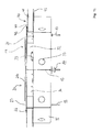
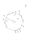
- Fig. 1a In the exemplary embodiment, this has a circular, rotatably arranged cover 20, which comprises a total of two sections 21 a, b.
- the cover 20 is associated with a support plate 24 which is disposed below the two sections 21 a, b.
- the cover 20 is fastened in the table connection pad 10 via the holder 25. Fixed to the holder 25 is the support plate 24.
- the holder 25 with arranged thereon support plate 24 is rotatable in total in the table connection pad 10 and the receiving tray 30 is arranged.
- the cover 20 closes an access opening 11 of the table connection panel 10 and is rotatable in the plane of the access opening 11. In the embodiment of Fig. 1 the access opening 11 is not completely covered, but it remains in the peripheral region, a gap 28, which can be used for example for the passage of cables or the like.
- the two sections 21 a, b of the cover 20 are displaceable relative to each other. By moving the sections 21 a, b relative to each other, the access opening 11 of the table connection panel 10 can be released or closed.
- a first portion 21 a of the cover 20 is lowered or depressed.
- the first section 21 a is this, as from Fig. 1b and later described Fig. 2b recognizable, spring-loaded.
- the second section 21 b slides onto the surface 22 a of the first section 21 a.
- the first portion 21 a is supported here on the support plate 24 from. This support plate 24 also receives the spring elements 29.
- the sections 21 a, b are on a plane and thus form a planar cover 20 for the table connection panel 10th
- the desk connection panel 10 additionally has a receiving tray 30.
- This has a bottom 31 and a peripheral wall 32.
- openings 33 are arranged.
- recordings 34 for the arrangement of plugs, sockets or the like are provided here. These have a predetermined breaking point and can be exposed if necessary.
- the actual receiving tray 30 is received in an outer shell 35, which serves, inter alia, to accommodate cables that are led out of the receiving tray 30, or cover.
- the outer shell 35 serves to fix the entire table connection panel 10, for example, from the underside to a table 45. In the outer shell 35 all cabling is performed and can, as in, for example, in Fig. 3 is shown, led out through a central aperture 33 from the outer shell 35 bundled.
- the receiving tray 30 and thus the entire table connection panel 10 are, for example, connected by screwing with the outer shell 35.
- the right angles from the The outer shell 35 extending mounting flanges 49 have for this purpose slots 48, without limiting the invention thereto, on the attachment of the outer shell 35 on a table bottom 43 (see. Fig. 1 b) can be carried out.
- the connection to a surrounding table top 44 forms the perpendicular to the receiving tray 30 away extending edge 26. This can be additionally provided with an example replaceable or in the design or material to the table top 44 adapted aperture 27.
- FIG. 1b The installation situation of a table connection panel 10 according to the invention is in Fig. 1b shown.
- the receiving tray 30 surrounding outer shell 35, in which the receiving tray 30 is secured by screws 13.
- the outer shell 35 is screwed below a table 45 on the underside of the table 43.
- the edge 26 or the aperture 27 of the table connection field 10 rests on the table top 44.
- the table 45 itself has an opening 41 into which the desk connection panel 10 is inserted.
- the edge 26 of the desk connection field 10 extending away from the table connection panel 10 or the access opening 11 rests on the edge region 42 of the opening 41 and thus supports the desk connection panel 10.
- the table connection panel 10 is thus arranged in the table level 40. Even when opening the cover 20 to release the access opening 11, no parts of the table connection panel 10 extend above the table level 40.
- the sections 21 a, b of the cover 20 are displaced in the plane of the access opening 11 or rotated about a central axis of rotation 16 , A pivoting or unfolding of the cover 20, as is known, for example, from the prior art, does not take place here. By twisting the cover 20 in the plane of the access opening 11, an all-round access to the access opening 11 can also take place without disruptive cover parts being present here.
- the receiving tray 30 is as shown Fig. 1b is removable, in the outer shell 35 a.
- the receiving tray 30 provides apertures 33 and receptacles 34 for plugs or other connection elements in the interior of the table connection pad 10.
- the wiring and other installation is housed in the outer shell 35. This serves at the same time for bundling and for receiving the wiring.
- the outer shell 35 has further openings 33, which also serve for the supply or discharge of cables or other lines.
- Fig. 1c shows the table connection panel 10 according to the invention in plan view. Recognizable here are the portions 21 a, b of the cover 20 and the remaining between the cover 20 and edge 26 gap 28. Shown is the desktop connection panel 10 in the non-installed state. Therefore, the outer shell 35, in which the receiving tray 30 is arranged with the access opening 11 concealing cover 20 and edge 26, recognizable. The outer shell 35 is connected via the mounting flanges 49 with a table bottom 43. After that, as in Fig. 1b shown, the receiving tray 30 with the cover 20 is sunk into an opening 41 in a Tischebene 40 and connected to the lower outer shell 35, for example. Via screws 13.
- the edge 26 rests on the table top 44 and can be provided with a shutter 27 to provide a visually appealing connection to the table top 44.
- the two sections 21 a, b are formed as circular segments and have different surface areas. During the first section 21 a, as already related to Fig. 1a described, lowered or depressible formed, the second portion 21 b relative to the first portion 21 a slidably disposed, in particular in the plane of the access opening 11 rotatably and is moved in use over the first portion 21 a. As a result, the access opening 11 is released.
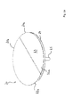
- Fig. 2a shows a representation of the cover 20. This has a total of two sections 21 a, b, which are formed as circular segments or circular sections. The two circle segments have different sizes.
- the first, in. Fig. 2a smaller section 21 a can be pressed against a support plate 24 and allows then the rotation of the second portion 21 b relative to the first portion 21 a.
- the support plate 24 has spring elements 29 (see. Fig. 2b ), which in the closed position of the cover 20, as this in Fig. 2a is shown, the first portion 21 a set to the same height as the second portion 21 b and thus allow a flush completion of the access opening 11 of the table connection panel 10.
- the support plate 24 is fixedly connected to the bracket 25.
- the holder 25 is arranged in the receiving tray 30 and rotatably supported there.
- the surface 22 a of the first section 21 a provides a sliding surface 23.
- the lower surface 22b of the second section 21b slides thereon during rotation or displacement of the section 21b.
- Fig. 2b shows the cover 20 in a side sectional view. Visible is the holder 25, on which the support plate 24 is arranged. In the support plate 24, the spring elements 29 are arranged, which cause a pushing back of the first portion 21 a in the starting position when the access opening 11 is completely closed with the cover 20. On the support plate 24 supports 37 are additionally arranged, which are moved together with the first portion 21 a in the guide 36 when a lowering of the first section 21 a in the direction of arrow A takes place.
- the holder 25 with the sections 21 a, b arranged thereon is arranged rotatably in the receiving tray 30. At the upper end of the bracket 25 is another bearing 38 having a pivot point 39.
- the second portion 21 b of the cover 20 is rotatable.
- a rotation of the second portion 21 b relative to the first portion 21 a is prevented by the fact that the portion 21 a, which is defined by a chord defined edge 15 of the second portion 21 b.
- the cover 20 can be moved only in the closed position or rotated in the plane of the access opening 11. A release of the access opening 11 is not possible.
- the first portion 21 a in the direction of the support plate 24 must be moved or depressed. As a result, the rotatability of the second portion 21 b is then ensured and this can be moved over the first portion 21 a and thereby release the access opening 11.
- a sleeve or a bearing is provided, in which the pin-like holder 25 is inserted and rotatable is stored.
- the invention of course includes all other suitable bearings and receptacles that allow rotation of the cover 20.
- the cover 20 with only two sections 21 a, b there is the possibility that the cover 20 is formed from more than two sections 21 a, b and these are designed segment-like. By shifting two or more segments, a variable release of the access opening 11 can then be performed.
- the rotatable embodiment of the cover 20 or sections 21 a, b also allows individual adjustment of the size of the access opening 11 and the positional orientation of the access opening 11. If, for example, only a connection such as a socket within the receiving tray 30 is required, then only the area the access opening 11 are released, which covers the part of the receiving tray 30 having the required plug or the box.
- the entire access opening 11 is first released by the second portion 21 b is completely shifted over the first portion 21 a. As a result, the access opening 11 is released and it can be used or occupied the existing connections. After the installation, the access opening 11 can be fully closed again. The arranged cables and lines are led out through the gap 28 from the table connection field 10.
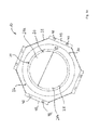
- Fig. 2c shows the cover 20 in the lower view. Visible here is the support plate 24 in which a plurality of spring elements 29 are received, which act on the first portion 21a and hold in the closed position (see. Fig. 2b ). Against the spring elements 29, the first portion 21 a in the direction of the support plate 24 is displaced or depressed to allow a displacement or rotation of the second portion 21 b in the plane of the access opening 11. The second portion 21 b slides on the first portion 21 a and releases the access opening 11. The surface 22b slides on the corresponding surface 22a (see FIG. Fig. 1a ) of the first section 21a. A displacement or rotation of the second portion 21 b takes place in the direction of arrow B.
- supports 37 are additionally provided in the support plate 24.
- the support plate has guides 26 which are guided over the supports 37.
- the entire cover 20 is rotatably mounted in the pivot point 39. Thus, a complete rotation of the cover 20 in the plane of the access opening 11 is possible.
- Fig. 3 shows an embodiment of the outer shell 35.
- This has a central opening 33 through which cables and leads are led out of the outer shell 35.
- the receiving tray 30 with cover 20 In the outer shell 35 is arranged in the installed state of the Tischan gleichfeldes 10, the receiving tray 30 with cover 20.
- the outer shell 35 is connected to the receiving tray 30 via the screws inserted into the holes 47 13.
- the outer shell 35 is in the installed state from below attached to a table 45.
- the mounting flanges 49 serve. These have slots 48 through which a screwing of the outer shell with the table bottom 43 is possible.
- the peripheral wall 32 of the outer shell 35 has additional apertures 33. These can also be used to lead cables or lines into the outer shell.
- the outer shell 35 is provided as a sheet metal bending part. In addition to the screwing with the table bottom 43, an arrangement can also be made by gluing or the like.
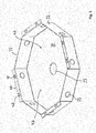
- Fig. 4 shows a bottom view of another embodiment of the in Fig. 3 illustrated outer shell 35.
- the outer shell 35 is formed in the embodiment in total octagonal. Of course, a square or polygonal design is also conceivable.
- the opening 33 and the holes 47 are provided in the bottom 32 of the outer shell 35.
- On the underside of the table 43 facing side of the outer shell 35 is followed by a sleeve or the like, which serves as a bearing or receptacle for the holder 25 of the cover 20 and the rotatable arrangement allows.
- the proposal includes
- a table connection panel (10) having a cover (20) having access opening (11), wherein the cover (20) in a plane (12) of the access opening (11) from a closed position to an open position is displaceable, wherein the cover has two or more relatively displaceable, rotatably mounted portions (21 a, b).
- a table connection panel as described above, wherein the cover (20) at least a first with respect to the plane (12) of the access opening (11) lowered or depressible portion (21 a, b) and at least a second portion (21 b), wherein the second Section (21 b) in the open position wholly or partially on the lowered or depressed first portion (21 a) can be pushed.
- a table connection panel as described above, wherein on surfaces facing each other (22a, b) of the first and / or second portion (21 a, b) sliding surfaces (23) or plain bearings are provided.
- a table connection panel as described above, wherein the first portion (21 a), second portion (21 b) and support plate (24) in the plane (12) of the access opening (11) rotatably, in particular independently of each other rotatably arranged.
- a table connection panel as described above, wherein the cover (20) in the manner of an iris diaphragm with a plurality of sections (21 a, b) is formed and wherein as sections (21 a, b) fins are provided.
- a table connection panel as described above, wherein in and / or on the receiving tray (30) and / or the outer shell (35) at least one holder (25) or support for the cover (20) is provided.
- a desktop connection panel as described above, wherein in or below the receiving tray (30) a communication device, a control device for room or presentation technology, a computer unit, a screen, a cable storage or the like is arranged.
- the proposal further comprises a table (45) with at least one table connection panel (10) as previously described.
Landscapes
- Tables And Desks Characterized By Structural Shape (AREA)
Applications Claiming Priority (1)
| Application Number | Priority Date | Filing Date | Title |
|---|---|---|---|
| DE201220100697 DE202012100697U1 (de) | 2012-02-29 | 2012-02-29 | Tischanschlussfeld |
Publications (2)
| Publication Number | Publication Date |
|---|---|
| EP2634878A1 true EP2634878A1 (fr) | 2013-09-04 |
| EP2634878B1 EP2634878B1 (fr) | 2016-12-28 |
Family
ID=47554549
Family Applications (1)
| Application Number | Title | Priority Date | Filing Date |
|---|---|---|---|
| EP13156054.2A Not-in-force EP2634878B1 (fr) | 2012-02-29 | 2013-02-20 | Panneau de connexion de table |
Country Status (2)
| Country | Link |
|---|---|
| EP (1) | EP2634878B1 (fr) |
| DE (1) | DE202012100697U1 (fr) |
Cited By (1)
| Publication number | Priority date | Publication date | Assignee | Title |
|---|---|---|---|---|
| DE202015006221U1 (de) | 2015-09-09 | 2015-10-16 | Axel R. Hidde | Einrichtung für den Anschluß elektrischer Geräte |
Families Citing this family (5)
| Publication number | Priority date | Publication date | Assignee | Title |
|---|---|---|---|---|
| DE102013000827B4 (de) * | 2013-01-18 | 2019-07-04 | Maximilian Rüttiger | Kabeldose oder Kabeldurchführung mit Ringspalt |
| DE102013000829B4 (de) * | 2013-01-18 | 2015-03-12 | Maximilian Rüttiger | Kabeldurchführung |
| DE102013007043A1 (de) * | 2013-01-18 | 2014-07-24 | Maximilian Rüttiger | Abdeckung für Kabeldose |
| DE202013012117U1 (de) * | 2013-01-18 | 2015-05-06 | Maximilian Rüttiger | Haltevorrichtung für Kabeldose |
| DE102013000906A1 (de) * | 2013-01-18 | 2014-07-24 | Maximilian Rüttiger | Kabeldose |
Citations (4)
| Publication number | Priority date | Publication date | Assignee | Title |
|---|---|---|---|---|
| US3956573A (en) * | 1974-04-29 | 1976-05-11 | Textron, Inc. | Flush type floor box |
| DE8527566U1 (de) * | 1985-09-27 | 1985-12-05 | Paul Henke GmbH & Co KG, 4972 Löhne | Einfassung für Kabeldurchlaßöffnungen |
| US5686700A (en) * | 1994-11-14 | 1997-11-11 | Carpin Manufacturing, Inc. | Adjustable cable management grommet |
| EP2220963A2 (fr) * | 2009-02-24 | 2010-08-25 | Comfortable computer integriert GmbH | Table de travail |
Family Cites Families (3)
| Publication number | Priority date | Publication date | Assignee | Title |
|---|---|---|---|---|
| US20070235222A1 (en) * | 2006-04-07 | 2007-10-11 | Hubbard Robert A | Cable management unit |
| DE202006016371U1 (de) * | 2006-10-20 | 2008-02-21 | GESIKA Büromöbelwerk GmbH | Vorrichtung zur Energieversorgung von Möbeln |
| AT504490B1 (de) * | 2007-01-08 | 2008-06-15 | Franz Blaha Sitz Und Bueromoeb | Nach mehreren seiten zu öffnende klappen als kabeldurchlass und abdeckung |
-
2012
- 2012-02-29 DE DE201220100697 patent/DE202012100697U1/de not_active Expired - Lifetime
-
2013
- 2013-02-20 EP EP13156054.2A patent/EP2634878B1/fr not_active Not-in-force
Patent Citations (4)
| Publication number | Priority date | Publication date | Assignee | Title |
|---|---|---|---|---|
| US3956573A (en) * | 1974-04-29 | 1976-05-11 | Textron, Inc. | Flush type floor box |
| DE8527566U1 (de) * | 1985-09-27 | 1985-12-05 | Paul Henke GmbH & Co KG, 4972 Löhne | Einfassung für Kabeldurchlaßöffnungen |
| US5686700A (en) * | 1994-11-14 | 1997-11-11 | Carpin Manufacturing, Inc. | Adjustable cable management grommet |
| EP2220963A2 (fr) * | 2009-02-24 | 2010-08-25 | Comfortable computer integriert GmbH | Table de travail |
Cited By (2)
| Publication number | Priority date | Publication date | Assignee | Title |
|---|---|---|---|---|
| DE202015006221U1 (de) | 2015-09-09 | 2015-10-16 | Axel R. Hidde | Einrichtung für den Anschluß elektrischer Geräte |
| DE102016010711A1 (de) | 2015-09-09 | 2017-03-09 | Axel R. Hidde | Einrichtung für den Anschluß elektrischer Geräte |
Also Published As
| Publication number | Publication date |
|---|---|
| EP2634878B1 (fr) | 2016-12-28 |
| DE202012100697U1 (de) | 2012-12-18 |
Similar Documents
| Publication | Publication Date | Title |
|---|---|---|
| EP2634878B1 (fr) | Panneau de connexion de table | |
| DE102018009948B4 (de) | Installationselement für Steckdosenelemente | |
| DE10150013A1 (de) | Bewegliche Tischklappe | |
| EP0828326B1 (fr) | Colonne d'énergie | |
| DE102013003519B4 (de) | Duschabtrennung | |
| EP0219640A2 (fr) | Appareil d'installation à couvercle rabattable | |
| WO2006042644A1 (fr) | Dispositif pour le logement d'au moins un boitier de prise | |
| DE69419972T2 (de) | Distributionskanal einschliesslich Terminalanordnungen | |
| DE9210728U1 (de) | Multifunktionales Wandelement für Büro- und sonstige Arbeitsplatzeinrichtungen | |
| EP3673543B1 (fr) | Panneau de connecteurs de plateau de table ou d'appareil | |
| DE102016124303A1 (de) | Verschlusssystem für ein Möbel | |
| EP2461444B1 (fr) | Boîtier d'appareil encastrable pivotant pour un caniveau pour câbles | |
| EP2523302A2 (fr) | Disque central d'un appareil d'installation électrique destiné au dépôt et au chargement électrique d'un appareil de communication audio mobile | |
| DE202009010646U1 (de) | Tischmöbel | |
| DE3237698C2 (fr) | ||
| DE2819628C3 (de) | Hängeschrank für Einbauküchen | |
| DE69125213T2 (de) | Speisegerät für eine Kabelkanaleinrichtung | |
| EP2380433A1 (fr) | Couvercle pour aquarium, terrarium ou analogues | |
| DE69822865T2 (de) | Beleuchtungsvorrichtung mit zusatzleuchte | |
| EP1340546A2 (fr) | Système d'alimentation | |
| EP1317041B1 (fr) | Boitier d'appareil pour dispositif d'installation électrique | |
| CH641334A5 (en) | Furniture for workplace design in modular construction | |
| DE202008009377U1 (de) | Kabeldurchlaß | |
| DE102023119311A1 (de) | Translations-Rotations-Anordnung und Möbel- oder Haushaltsgeräteelement | |
| DE102021132935A1 (de) | Bodenkanal mit schwenkbarer Abdeckung |
Legal Events
| Date | Code | Title | Description |
|---|---|---|---|
| PUAI | Public reference made under article 153(3) epc to a published international application that has entered the european phase |
Free format text: ORIGINAL CODE: 0009012 |
|
| AK | Designated contracting states |
Kind code of ref document: A1 Designated state(s): AL AT BE BG CH CY CZ DE DK EE ES FI FR GB GR HR HU IE IS IT LI LT LU LV MC MK MT NL NO PL PT RO RS SE SI SK SM TR |
|
| AX | Request for extension of the european patent |
Extension state: BA ME |
|
| 17P | Request for examination filed |
Effective date: 20140301 |
|
| RBV | Designated contracting states (corrected) |
Designated state(s): AL AT BE BG CH CY CZ DE DK EE ES FI FR GB GR HR HU IE IS IT LI LT LU LV MC MK MT NL NO PL PT RO RS SE SI SK SM TR |
|
| 17Q | First examination report despatched |
Effective date: 20150330 |
|
| GRAP | Despatch of communication of intention to grant a patent |
Free format text: ORIGINAL CODE: EPIDOSNIGR1 |
|
| INTG | Intention to grant announced |
Effective date: 20160721 |
|
| GRAS | Grant fee paid |
Free format text: ORIGINAL CODE: EPIDOSNIGR3 |
|
| GRAA | (expected) grant |
Free format text: ORIGINAL CODE: 0009210 |
|
| AK | Designated contracting states |
Kind code of ref document: B1 Designated state(s): AL AT BE BG CH CY CZ DE DK EE ES FI FR GB GR HR HU IE IS IT LI LT LU LV MC MK MT NL NO PL PT RO RS SE SI SK SM TR |
|
| REG | Reference to a national code |
Ref country code: GB Ref legal event code: FG4D Free format text: NOT ENGLISH |
|
| REG | Reference to a national code |
Ref country code: CH Ref legal event code: EP |
|
| REG | Reference to a national code |
Ref country code: AT Ref legal event code: REF Ref document number: 858020 Country of ref document: AT Kind code of ref document: T Effective date: 20170115 |
|
| REG | Reference to a national code |
Ref country code: IE Ref legal event code: FG4D Free format text: LANGUAGE OF EP DOCUMENT: GERMAN |
|
| REG | Reference to a national code |
Ref country code: CH Ref legal event code: NV Representative=s name: RENTSCH PARTNER AG, CH |
|
| REG | Reference to a national code |
Ref country code: DE Ref legal event code: R096 Ref document number: 502013005873 Country of ref document: DE |
|
| REG | Reference to a national code |
Ref country code: FR Ref legal event code: PLFP Year of fee payment: 5 |
|
| REG | Reference to a national code |
Ref country code: NL Ref legal event code: FP |
|
| PG25 | Lapsed in a contracting state [announced via postgrant information from national office to epo] |
Ref country code: LV Free format text: LAPSE BECAUSE OF FAILURE TO SUBMIT A TRANSLATION OF THE DESCRIPTION OR TO PAY THE FEE WITHIN THE PRESCRIBED TIME-LIMIT Effective date: 20161228 |
|
| REG | Reference to a national code |
Ref country code: DE Ref legal event code: R082 Ref document number: 502013005873 Country of ref document: DE Representative=s name: BAUMANN, RUEDIGER, DIPL.-FORSTW. DR. RER. NAT., DE Ref country code: DE Ref legal event code: R082 Ref document number: 502013005873 Country of ref document: DE Representative=s name: BAUMANN, RUEDIGER, DIPL.-FORSTW. UNIV. DR. RER, DE |
|
| REG | Reference to a national code |
Ref country code: LT Ref legal event code: MG4D |
|
| PG25 | Lapsed in a contracting state [announced via postgrant information from national office to epo] |
Ref country code: GR Free format text: LAPSE BECAUSE OF FAILURE TO SUBMIT A TRANSLATION OF THE DESCRIPTION OR TO PAY THE FEE WITHIN THE PRESCRIBED TIME-LIMIT Effective date: 20170329 Ref country code: LT Free format text: LAPSE BECAUSE OF FAILURE TO SUBMIT A TRANSLATION OF THE DESCRIPTION OR TO PAY THE FEE WITHIN THE PRESCRIBED TIME-LIMIT Effective date: 20161228 Ref country code: SE Free format text: LAPSE BECAUSE OF FAILURE TO SUBMIT A TRANSLATION OF THE DESCRIPTION OR TO PAY THE FEE WITHIN THE PRESCRIBED TIME-LIMIT Effective date: 20161228 Ref country code: NO Free format text: LAPSE BECAUSE OF FAILURE TO SUBMIT A TRANSLATION OF THE DESCRIPTION OR TO PAY THE FEE WITHIN THE PRESCRIBED TIME-LIMIT Effective date: 20170328 |
|
| PG25 | Lapsed in a contracting state [announced via postgrant information from national office to epo] |
Ref country code: RS Free format text: LAPSE BECAUSE OF FAILURE TO SUBMIT A TRANSLATION OF THE DESCRIPTION OR TO PAY THE FEE WITHIN THE PRESCRIBED TIME-LIMIT Effective date: 20161228 Ref country code: HR Free format text: LAPSE BECAUSE OF FAILURE TO SUBMIT A TRANSLATION OF THE DESCRIPTION OR TO PAY THE FEE WITHIN THE PRESCRIBED TIME-LIMIT Effective date: 20161228 Ref country code: FI Free format text: LAPSE BECAUSE OF FAILURE TO SUBMIT A TRANSLATION OF THE DESCRIPTION OR TO PAY THE FEE WITHIN THE PRESCRIBED TIME-LIMIT Effective date: 20161228 |
|
| PG25 | Lapsed in a contracting state [announced via postgrant information from national office to epo] |
Ref country code: RO Free format text: LAPSE BECAUSE OF FAILURE TO SUBMIT A TRANSLATION OF THE DESCRIPTION OR TO PAY THE FEE WITHIN THE PRESCRIBED TIME-LIMIT Effective date: 20161228 Ref country code: CZ Free format text: LAPSE BECAUSE OF FAILURE TO SUBMIT A TRANSLATION OF THE DESCRIPTION OR TO PAY THE FEE WITHIN THE PRESCRIBED TIME-LIMIT Effective date: 20161228 Ref country code: SK Free format text: LAPSE BECAUSE OF FAILURE TO SUBMIT A TRANSLATION OF THE DESCRIPTION OR TO PAY THE FEE WITHIN THE PRESCRIBED TIME-LIMIT Effective date: 20161228 Ref country code: EE Free format text: LAPSE BECAUSE OF FAILURE TO SUBMIT A TRANSLATION OF THE DESCRIPTION OR TO PAY THE FEE WITHIN THE PRESCRIBED TIME-LIMIT Effective date: 20161228 Ref country code: IS Free format text: LAPSE BECAUSE OF FAILURE TO SUBMIT A TRANSLATION OF THE DESCRIPTION OR TO PAY THE FEE WITHIN THE PRESCRIBED TIME-LIMIT Effective date: 20170428 |
|
| PG25 | Lapsed in a contracting state [announced via postgrant information from national office to epo] |
Ref country code: SM Free format text: LAPSE BECAUSE OF FAILURE TO SUBMIT A TRANSLATION OF THE DESCRIPTION OR TO PAY THE FEE WITHIN THE PRESCRIBED TIME-LIMIT Effective date: 20161228 Ref country code: ES Free format text: LAPSE BECAUSE OF FAILURE TO SUBMIT A TRANSLATION OF THE DESCRIPTION OR TO PAY THE FEE WITHIN THE PRESCRIBED TIME-LIMIT Effective date: 20161228 Ref country code: BG Free format text: LAPSE BECAUSE OF FAILURE TO SUBMIT A TRANSLATION OF THE DESCRIPTION OR TO PAY THE FEE WITHIN THE PRESCRIBED TIME-LIMIT Effective date: 20170328 Ref country code: PL Free format text: LAPSE BECAUSE OF FAILURE TO SUBMIT A TRANSLATION OF THE DESCRIPTION OR TO PAY THE FEE WITHIN THE PRESCRIBED TIME-LIMIT Effective date: 20161228 Ref country code: PT Free format text: LAPSE BECAUSE OF FAILURE TO SUBMIT A TRANSLATION OF THE DESCRIPTION OR TO PAY THE FEE WITHIN THE PRESCRIBED TIME-LIMIT Effective date: 20170428 Ref country code: IT Free format text: LAPSE BECAUSE OF FAILURE TO SUBMIT A TRANSLATION OF THE DESCRIPTION OR TO PAY THE FEE WITHIN THE PRESCRIBED TIME-LIMIT Effective date: 20161228 |
|
| PG25 | Lapsed in a contracting state [announced via postgrant information from national office to epo] |
Ref country code: MC Free format text: LAPSE BECAUSE OF FAILURE TO SUBMIT A TRANSLATION OF THE DESCRIPTION OR TO PAY THE FEE WITHIN THE PRESCRIBED TIME-LIMIT Effective date: 20161228 |
|
| REG | Reference to a national code |
Ref country code: CH Ref legal event code: PCAR Free format text: NEW ADDRESS: BELLERIVESTRASSE 203 POSTFACH, 8034 ZUERICH (CH) Ref country code: DE Ref legal event code: R097 Ref document number: 502013005873 Country of ref document: DE |
|
| PLBE | No opposition filed within time limit |
Free format text: ORIGINAL CODE: 0009261 |
|
| STAA | Information on the status of an ep patent application or granted ep patent |
Free format text: STATUS: NO OPPOSITION FILED WITHIN TIME LIMIT |
|
| REG | Reference to a national code |
Ref country code: IE Ref legal event code: MM4A |
|
| PG25 | Lapsed in a contracting state [announced via postgrant information from national office to epo] |
Ref country code: DK Free format text: LAPSE BECAUSE OF FAILURE TO SUBMIT A TRANSLATION OF THE DESCRIPTION OR TO PAY THE FEE WITHIN THE PRESCRIBED TIME-LIMIT Effective date: 20161228 |
|
| 26N | No opposition filed |
Effective date: 20170929 |
|
| PG25 | Lapsed in a contracting state [announced via postgrant information from national office to epo] |
Ref country code: LU Free format text: LAPSE BECAUSE OF NON-PAYMENT OF DUE FEES Effective date: 20170220 |
|
| REG | Reference to a national code |
Ref country code: FR Ref legal event code: PLFP Year of fee payment: 6 |
|
| PG25 | Lapsed in a contracting state [announced via postgrant information from national office to epo] |
Ref country code: IE Free format text: LAPSE BECAUSE OF NON-PAYMENT OF DUE FEES Effective date: 20170220 Ref country code: SI Free format text: LAPSE BECAUSE OF FAILURE TO SUBMIT A TRANSLATION OF THE DESCRIPTION OR TO PAY THE FEE WITHIN THE PRESCRIBED TIME-LIMIT Effective date: 20161228 |
|
| PG25 | Lapsed in a contracting state [announced via postgrant information from national office to epo] |
Ref country code: MT Free format text: LAPSE BECAUSE OF FAILURE TO SUBMIT A TRANSLATION OF THE DESCRIPTION OR TO PAY THE FEE WITHIN THE PRESCRIBED TIME-LIMIT Effective date: 20161228 |
|
| PG25 | Lapsed in a contracting state [announced via postgrant information from national office to epo] |
Ref country code: HU Free format text: LAPSE BECAUSE OF FAILURE TO SUBMIT A TRANSLATION OF THE DESCRIPTION OR TO PAY THE FEE WITHIN THE PRESCRIBED TIME-LIMIT; INVALID AB INITIO Effective date: 20130220 |
|
| PG25 | Lapsed in a contracting state [announced via postgrant information from national office to epo] |
Ref country code: CY Free format text: LAPSE BECAUSE OF NON-PAYMENT OF DUE FEES Effective date: 20161228 |
|
| PG25 | Lapsed in a contracting state [announced via postgrant information from national office to epo] |
Ref country code: MK Free format text: LAPSE BECAUSE OF FAILURE TO SUBMIT A TRANSLATION OF THE DESCRIPTION OR TO PAY THE FEE WITHIN THE PRESCRIBED TIME-LIMIT Effective date: 20161228 |
|
| PG25 | Lapsed in a contracting state [announced via postgrant information from national office to epo] |
Ref country code: TR Free format text: LAPSE BECAUSE OF FAILURE TO SUBMIT A TRANSLATION OF THE DESCRIPTION OR TO PAY THE FEE WITHIN THE PRESCRIBED TIME-LIMIT Effective date: 20161228 |
|
| PG25 | Lapsed in a contracting state [announced via postgrant information from national office to epo] |
Ref country code: AL Free format text: LAPSE BECAUSE OF FAILURE TO SUBMIT A TRANSLATION OF THE DESCRIPTION OR TO PAY THE FEE WITHIN THE PRESCRIBED TIME-LIMIT Effective date: 20161228 |
|
| PGFP | Annual fee paid to national office [announced via postgrant information from national office to epo] |
Ref country code: NL Payment date: 20210218 Year of fee payment: 9 Ref country code: CH Payment date: 20210222 Year of fee payment: 9 Ref country code: FR Payment date: 20210217 Year of fee payment: 9 |
|
| PGFP | Annual fee paid to national office [announced via postgrant information from national office to epo] |
Ref country code: DE Payment date: 20210223 Year of fee payment: 9 Ref country code: AT Payment date: 20210216 Year of fee payment: 9 Ref country code: BE Payment date: 20210218 Year of fee payment: 9 Ref country code: GB Payment date: 20210222 Year of fee payment: 9 |
|
| REG | Reference to a national code |
Ref country code: DE Ref legal event code: R119 Ref document number: 502013005873 Country of ref document: DE |
|
| REG | Reference to a national code |
Ref country code: NL Ref legal event code: MM Effective date: 20220301 |
|
| REG | Reference to a national code |
Ref country code: CH Ref legal event code: PL |
|
| REG | Reference to a national code |
Ref country code: AT Ref legal event code: MM01 Ref document number: 858020 Country of ref document: AT Kind code of ref document: T Effective date: 20220220 |
|
| REG | Reference to a national code |
Ref country code: BE Ref legal event code: MM Effective date: 20220228 |
|
| GBPC | Gb: european patent ceased through non-payment of renewal fee |
Effective date: 20220220 |
|
| PG25 | Lapsed in a contracting state [announced via postgrant information from national office to epo] |
Ref country code: AT Free format text: LAPSE BECAUSE OF NON-PAYMENT OF DUE FEES Effective date: 20220220 |
|
| PG25 | Lapsed in a contracting state [announced via postgrant information from national office to epo] |
Ref country code: NL Free format text: LAPSE BECAUSE OF NON-PAYMENT OF DUE FEES Effective date: 20220301 Ref country code: FR Free format text: LAPSE BECAUSE OF NON-PAYMENT OF DUE FEES Effective date: 20220228 |
|
| PG25 | Lapsed in a contracting state [announced via postgrant information from national office to epo] |
Ref country code: LI Free format text: LAPSE BECAUSE OF NON-PAYMENT OF DUE FEES Effective date: 20220228 Ref country code: GB Free format text: LAPSE BECAUSE OF NON-PAYMENT OF DUE FEES Effective date: 20220220 Ref country code: DE Free format text: LAPSE BECAUSE OF NON-PAYMENT OF DUE FEES Effective date: 20220901 Ref country code: CH Free format text: LAPSE BECAUSE OF NON-PAYMENT OF DUE FEES Effective date: 20220228 |
|
| PG25 | Lapsed in a contracting state [announced via postgrant information from national office to epo] |
Ref country code: BE Free format text: LAPSE BECAUSE OF NON-PAYMENT OF DUE FEES Effective date: 20220228 |