EP2635404B1 - Air-type shot-treatment machine - Google Patents
Air-type shot-treatment machine Download PDFInfo
- Publication number
- EP2635404B1 EP2635404B1 EP11741297.3A EP11741297A EP2635404B1 EP 2635404 B1 EP2635404 B1 EP 2635404B1 EP 11741297 A EP11741297 A EP 11741297A EP 2635404 B1 EP2635404 B1 EP 2635404B1
- Authority
- EP
- European Patent Office
- Prior art keywords
- support member
- rotational axis
- moving
- motor
- shots
- Prior art date
- Legal status (The legal status is an assumption and is not a legal conclusion. Google has not performed a legal analysis and makes no representation as to the accuracy of the status listed.)
- Active
Links
Images




Classifications
-
- B—PERFORMING OPERATIONS; TRANSPORTING
- B24—GRINDING; POLISHING
- B24C—ABRASIVE OR RELATED BLASTING WITH PARTICULATE MATERIAL
- B24C3/00—Abrasive blasting machines or devices; Plants
- B24C3/18—Abrasive blasting machines or devices; Plants essentially provided with means for moving workpieces into different working positions
- B24C3/20—Abrasive blasting machines or devices; Plants essentially provided with means for moving workpieces into different working positions the work being supported by turntables
- B24C3/22—Apparatus using nozzles
-
- B—PERFORMING OPERATIONS; TRANSPORTING
- B24—GRINDING; POLISHING
- B24C—ABRASIVE OR RELATED BLASTING WITH PARTICULATE MATERIAL
- B24C1/00—Methods for use of abrasive blasting for producing particular effects; Use of auxiliary equipment in connection with such methods
- B24C1/10—Methods for use of abrasive blasting for producing particular effects; Use of auxiliary equipment in connection with such methods for compacting surfaces, e.g. shot-peening
Definitions
- This invention relates to an air-type shot-treatment machine.
- an air-type shot-treatment machine is used for processing products by projecting shots at them.
- products that have a plurality of gears coaxially disposed on a shaft with predetermined intervals, or products that have a plurality of gears coaxially disposed on a shaft in contact with each other are processed by projecting shots while a support member to hold the products and a nozzle for projecting the shots are fixed in position.
- an air-type shot-treatment machine having a nozzle that can ascend and descend is provided so as to avoid the change of the tooling being required when the respective gears are replaced and processed.
- Patent Document 1 Japanese Patent Laid-open Publication No. H8-216024 .
- Document EP 1254744 discloses an air-type shot-treatment machine according to the preamble of claim 1.
- the entire nozzle, the pressurized tank, and several types of valves attached to them, etc. can be lifted and lowered together.
- much equipment is required, and the machine becomes large.
- many tanks are required, and piping systems become complicated.
- the entire structure of the machine becomes complicated.
- This invention is conceived to solve the problems explained in the above paragraphs.
- the purpose of this invention is to reduce the changes in the conditions of the processing for projecting shots, and to achieve downsizing of the air-type shot-treatment machine and simplification of its structure.
- an air-type shot-treatment machine of a first aspect of this invention comprises:
- the support member is movable in a direction along its rotational axis by means of the moving device controlled by the control device.
- the article can be properly processed in response to the shape of the article.
- An air-type shot-treatment machine of a second aspect has the following constitution:
- the motor for moving the support member in the direction along the rotational axis of the support member which motor acts as a driving source disposed at the moving device, is disposed above the support member.
- the shots projected from the nozzle can be prevented from hitting the motor for moving the support member.
- An air-type shot-treatment machine of a third aspect has the following constitution:
- the mechanism for transmitting a rotational force of the rotational device is disposed at the side of the other end of the rotational axis of the support member, namely, at the side opposite the location of the motor for moving the support member.
- the motor for rotating the support member is disposed at the side of one end of the mechanism for transmitting a rotational force in the direction of the rotational axis of the support member, namely, at the side of the mechanism toward the motor for moving the support member.
- An air-type shot-treatment machine of a fourth aspect has the following constitution:
- the motor for rotating the support member is disposed in the housing of the moving portion, which housing has a box-like shape.
- the shots projected from the nozzle can be prevented from hitting the motor for rotating the support member.
- An air-type shot-treatment machine of a fifth aspect has the following constitution:
- An air-type shot-treatment machine of a sixth aspect has the following constitution:
- the present air-type shot-treatment machine even though the products have a plurality of gears coaxially disposed on a shaft in contact with each other, since the support member is continuously moved, the plurality of gears are processed in series by projecting the shots toward them. Thus, the plurality of gears disposed on a shaft in contact with each other can be efficiently processed.
- the change of the conditions of the processing for projecting shots can be eliminated. Further, the air-type shot-treatment machine can be downsized, and the structure of the machine can be simplified.
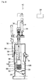
- the air-type shot-treatment machine 10 of an embodiment of this invention which machine is shown in Figs. 1-3 , is used for shot peening treatment works, for example.
- the machine 10 comprises a table 12, which acts as a support member, a holding mechanism 14, a nozzle 16, an adjusting device 18 to adjust the quantity of shots, a rotating device 20, a lifting and lowering device 22, which acts as a moving device, a control device 24, and a cabinet 26.
- the table 12 is housed in the cabinet 26 and has a rotational shaft 28 disposed on the central axis of the table 12.
- the rotational shaft 28 extends in the vertical direction and is rotatably supported by a case 62 of the rotating device 20, which device 20 is explained below in detail.
- the upper surface 12A of the table 12 is formed as a surface for supporting products 100, which are articles to be processed.
- gears of an automatic transmission (AT parts) as an example of the products 100 to be processed.
- the holding mechanism 14 comprises a holding rod 30, a rotating mechanism 32, an air cylinder 34, and a lever 36.
- the holding rod 30 extends in the vertical direction.
- the lower portion of the holding rod 30, which portion corresponds to the lower part from the center of the holding rod 30 in the longitudinal direction, is housed in the cabinet 26.
- a holding part 38 is disposed at the lower end of the holding rod 30 to push the products 100 toward the table 12.
- the rotating mechanism 32 is disposed at the upper wall of the cabinet 26.
- the rotating mechanism 32 supports the holding rod 30 so that it is rotatably and slidingly supported in the vertical direction by the upper wall of the cabinet 26.
- the air cylinder 34 is connected to the rotating mechanism 32 by means of the lever 36.
- the pushing force of the air cylinder 34 is transferred to the holding rod 30 by means of the lever 36. Consequently, the holding rod 30 pushes the products 100 toward the upper surface 12A of the table 12.
- the nozzle 16 is fixed to the side wall of the cabinet 26 so that the nozzle 16 does not move in the vertical direction and against the table 12.
- the nozzle 16 is oriented in the horizontal direction toward the central portion of the cabinet 26 where the products 100 are disposed.
- the nozzle 16 is connected to a pressurized tank 46 by means of a connecting device 44, comprising a wear-resistant hose 40 and a steel pipe 42.
- An adjusting device 18 to adjust the amount of shots comprises a mixing valve 48, which is disposed at the connecting device 44 explained in the above paragraph, adjusting equipment 49, and a cut gate 50 (a shutoff valve).
- the pressurized tank 46 is connected to a tank 52 for storing shots, and comprises a poppet valve 54 and a proportional feeder 56, which are disposed between the pressurized tank 46 and the tank 52 for storing shots.
- the poppet valve 54 disposed on the pressurized tank 46, is opened, and then appropriate quantities of shots are transferred to the pressurized tank 46 by means of the proportional feeder 56.
- the proportional feeder 56 and the poppet valve 54 are shut down, and then the pressurized tank 46 is compressed.
- the mixing valve 48 the cut gate 50 and the adjusting equipment 49 are opened, and then an appropriate quantity of shots is transferred to the mixing valve 48 from the pressurized tank 46 through the steel pipe 42, the cut gate 50, and the adjusting equipment 49.
- the shots are kept up by a stream of compressed air flowing to the mixing valve 48, the shots are accelerated. Then the shots are projected in the horizontal direction together with the compressed air from the nozzle 16 through the wear-resistant hose 40.
- rounded cut wires made by Toyo Seiko Co., Ltd., can be used as the shots.
- the rotating device 20 rotates the table 12. As shown in Fig. 3 , the rotating device 20 is integrated with a moving portion 72 of a lifting and lowering device 22, which is explained below in detail.
- the rotating device 20 comprises a motor for rotating the support member 58, a mechanism for transmitting a rotational force 60, and the case 62.
- the motor for rotating the support member 58 is disposed above the mechanism for transmitting a rotational force 60 and is disposed in the moving portion 72, which has a box-like shaped housing.
- the mechanism for transmitting a rotational force 60 is disposed below the table 12 and comprises a plurality of gears 64, 65, 66.
- the gear 64 is fixed to the rotational shaft of the motor for rotating the support member 58.
- the gear 65 is engaged with the gear 64 and is rotatably supported by the case 62. Further, the gear 66 is engaged with the gear 65 and fixed to the rotational shaft 28.
- the lifting and lowering device 22 lifts and lowers the table 12.
- the device 22 comprises a motor for lifting and lowering the support member 68, which motor acts as the motor for moving the support member, a ball screw assembly 70, and the moving portion 72.
- the motor for lifting and lowering the support member 68 is disposed on the upper wall of the cabinet 26 by means of a support structure 74, and is positioned above the table 12.
- the ball screw assembly 70 comprises a screw 76 extending vertically, and a nut 78 engaged with the screw 76.
- the screw 76 is connected to a slider 80.
- the slider 80 is supported by a pair of rails 82 disposed at the support structure 74, and can slide in a vertical direction.
- the slider 80 is integrated with and fixed to the moving portion 72.
- the nut 78 is connected to the rotating shaft of the motor for lifting and lowering the support member 68 by means of a mechanism for transmitting a rotational force (not shown).
- the air-type shot-treatment machine 10 is a vertical-type machine. Namely, the direction of the rotational axis of the support member corresponds to the vertical direction, and the table 12 can move in that direction.
- the control device 24 comprises an electrical circuit inside the device 24.
- the control device 24 controls the movements of the mixing valve 48, the adjusting equipment 49, the cut gate 50, the poppet valve 54, the proportional feeder 56, the motor for rotating the support member 58, the motor for lifting and lowering the support member 68, etc.
- the details of the function of the control device 24 are explained later, together with an explanation on the shot peening treatment.
- the air-type shot-treatment machine 10 further comprises the following elements for recovering the shots, in addition to the system explained in the above paragraphs: Namely, for the air-type shot-treatment machine 10, as shown in Fig. 1 , the shots projected toward the products 100 are collected in a hopper 84 disposed below the table 12, transferred to a horizontal screw-type conveyor 86, and then lifted by means of a vertical screw-type conveyor 88. The lifted shots are stored in the tank 52, and then pass through a separator 90.
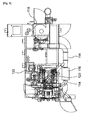
- the entire constitution of the air-type shot-treatment machine 10 is shown in Figs. 4-6 .
- dust generated in the cabinet 26 during the shot peening treatment is transferred to a dust collector 118 from a suction port 112 together with air suctioned by a ventilator 110 through a duct 114 and a settling chamber 116.
- the dust collector 118 the dust is filtered, and air is discharged.
- the dust suctioned from the separator 90 is transferred to the dust collector 118 through a settling chamber 120, and is filtered.
- a fine powder that is filtered at the settling chamber 116 and the settling chamber 120 is transferred to a box 122 for receiving fine powder.
- Some of the shots are transferred to a sieve 124 for classifying the shots from the tank 52 for storing shots.
- the usable shots are transferred to the lower portion of the vertical screw-type conveyor 88, and are reused.
- the fine powder separated by the sieve 124 for classifying the shots is transferred to the box 122 for receiving fine powder.
- One type of products 100 is a plurality of gears 104 coaxially integrated with a shaft 102 with predetermined intervals (see Fig. 7 ), and the other type of products 100 is a plurality of gears 108 coaxially disposed on a shaft 106 in contact with each other (see Fig. 8 ).
- an ascending and descending door 92 shown in Fig. 1 , of the cabinet 26, is opened. Then a product 100 is placed on the upper surface 12A of the table 12. At that time, the shaft 102 is held by the table 12 so that the longitudinal direction of the shaft 102 corresponds to the vertical direction. Then the ascending and descending door 92 is closed, and the product 100 is fixed on the table 12 by means of the holding mechanism 14.
- a start switch on a console panel 126 shown in Fig. 4 , is turned on. Based on this operation, a start signal is transmitted from the console panel 126 to the control device 24.
- the control device 24 receives the start signal, the device 24 rotates the table 12 by driving the motor for rotating the support member 58, and then starts the processing for shot peening the product 100 by projecting the shots from the nozzle 16 toward the product 100, while controlling the mixing valve 48, the adjusting equipment 49, the cut gate 50, the poppet valve 54, the proportional feeder 56, etc.
- control device 24 controls the motor for lifting and lowering the support member 68 so that the following steps are alternately carried out:
- the control device 24 controls the motor for lifting and lowering the support member 68 so that the table 12 is stopped at three respective positions, where the gears 104 can be processed.
- the control device 24 controls the motor 68 and precisely stops the table 12 at the required positions so that the shots projected from the nozzle 16 can properly hit each gear 104.
- the control device 24 controls the motor for lifting and lowering the support member 68 so that the plurality of gears 108 are processed in series by projecting the shots toward them while the table 12 is continuously lifted.
- the control device 24 controls the motor 68 so that the table 12 can be continuously lifted at a constant speed.
- control device 24 controls the motor for lifting and lowering the support member 68 so that the speed of ascent of the table 12 is changed in response to the shape of the product 100 to be processed. For example, when the thickness or the diameter of the gears 104 (108) is large, the speed of ascent of the table 12 is reduced. In contrast, when the thickness or the diameter of the gears 104 (108) is small, the speed of ascent of the table 12 is increased.
- the control device 24 stops projecting the shots by controlling the movements of the mixing valve 48, the adjusting equipment 49, the cut gate 50, the poppet valve 54, the proportional feeder 56, etc. Then the control device 24 stops the motor for rotating the support member 58 and the motor for lifting and lowering the support member 68. Then the product 100 is released from being held by the holding mechanism 14, the ascending and descending door 92 is opened, and the product 100 is taken out from the cabinet 26. Based on all of these operations, the shot peening treatment is completed.
- the nozzle 16 is fixed in the vertical direction.
- any change of the deformation of the wear-resistant hose 40 connecting the nozzle 16 and the pressurized tank 46 can be eliminated. Consequently, the change in the conditions for the processing for projecting shots can be eliminated.
- the table 12 can ascend and descend in a direction along its rotational axis and is lifted and lowered by the lifting and lowering device 22, which is controlled by the control device 24.
- the present machine can be downsized compared to a system in which the entire nozzle 16, a pressurized tank 46, and several types of valves attached to them, etc., are lifted and lowered together, the structure of the machine can be simplified.
- the motor for lifting and lowering the support member 68 which motor acts as a driving source disposed at the lifting and lowering device 22, is disposed above the table 12.
- the shots projected from the nozzle 16 can be prevented from hitting the motor 68.
- the mechanism for transmitting a rotational force 60 of the rotating device 20 is disposed below the table 12.
- the motor for rotating the support member 58 is disposed above the mechanism 60. Namely, the motor 58 is disposed at the side of the mechanism 60 toward the motor for lifting and lowering the support member 68.
- the air-type shot-treatment machine 10 can be downsized in the vertical direction.
- the motor for rotating the support member 58 is disposed in the housing of the moving portion 72, which housing has a box-like shape. Thus, the shots projected from the nozzle 16 can be prevented from hitting the motor 58.
- each gear 104 can be properly processed by projecting the shots 17 toward the gear 104.
- the plurality of gears 108 that are disposed on a shaft 106 in contact with each other can be efficiently processed.
- the product 100 can be properly processed in response to its shape.
- the air-type shot-treatment machine 10 is used as a shot peening treatment machine. However, it may be used as a shot blasting machine.
- the table 12 is used as a support member.
- a hanger that is suspended from an upper portion of the machine may be used as a support member.
- control device 24 controls the table 12 so that the table 12 ascends so as to carry out the shot peening treatment from the top gear of the plurality of gears 104 (108).
- the table 12 may be controlled so that it descends so as to carry out the shot peening treatment from the bottom gear of the plurality of gears 104 (108).
- the air-type shot-treatment machine 10 is a vertical type. However, it may be a horizontal type. In this case, the rotational axis of the table 12 extends horizontally.
Landscapes
- Engineering & Computer Science (AREA)
- Mechanical Engineering (AREA)
- Auxiliary Devices For Machine Tools (AREA)
- Spray Control Apparatus (AREA)
- Cleaning In General (AREA)
Priority Applications (1)
| Application Number | Priority Date | Filing Date | Title |
|---|---|---|---|
| PL11741297T PL2635404T3 (pl) | 2010-11-02 | 2011-06-29 | Maszyna do obróbki śrutowaniem typu pneumatycznego |
Applications Claiming Priority (2)
| Application Number | Priority Date | Filing Date | Title |
|---|---|---|---|
| JP2010246368A JP2012096326A (ja) | 2010-11-02 | 2010-11-02 | エア式ショット処理装置 |
| PCT/JP2011/003703 WO2012060028A1 (en) | 2010-11-02 | 2011-06-29 | Air-type Shot-Treatment Machine |
Publications (2)
| Publication Number | Publication Date |
|---|---|
| EP2635404A1 EP2635404A1 (en) | 2013-09-11 |
| EP2635404B1 true EP2635404B1 (en) | 2014-10-22 |
Family
ID=44588150
Family Applications (1)
| Application Number | Title | Priority Date | Filing Date |
|---|---|---|---|
| EP11741297.3A Active EP2635404B1 (en) | 2010-11-02 | 2011-06-29 | Air-type shot-treatment machine |
Country Status (7)
| Country | Link |
|---|---|
| US (1) | US9248547B2 (pl) |
| EP (1) | EP2635404B1 (pl) |
| JP (1) | JP2012096326A (pl) |
| KR (1) | KR20130139887A (pl) |
| CN (1) | CN103153543B (pl) |
| PL (1) | PL2635404T3 (pl) |
| WO (1) | WO2012060028A1 (pl) |
Families Citing this family (5)
| Publication number | Priority date | Publication date | Assignee | Title |
|---|---|---|---|---|
| KR101531028B1 (ko) * | 2014-10-15 | 2015-07-06 | 천흥륭석재(주) | 현무암 가공장치 및 이를 이용하여 가공된 현무암 제품 |
| CN110548729B (zh) * | 2018-06-01 | 2024-05-28 | 大连福兰特科技有限公司 | 一种冰粒喷射式表面处理设备 |
| KR102045963B1 (ko) * | 2019-08-09 | 2019-12-02 | (주)중앙종합안전기술연구원 | 블라스터 및 이를 이용한 강재 바탕처리 공법 |
| CN110918223A (zh) * | 2019-11-21 | 2020-03-27 | 中国石油大学(华东) | 一种利用弹丸动能清除水生污损生物的方法及装置 |
| KR102851950B1 (ko) * | 2024-10-04 | 2025-08-28 | 글로닉스(주) | 히터블록 표면처리용 샌드 블라스트장치 |
Family Cites Families (12)
| Publication number | Priority date | Publication date | Assignee | Title |
|---|---|---|---|---|
| US1940972A (en) * | 1931-07-09 | 1933-12-26 | Walter G Schwartzkopf | Blast nozzle |
| JP3401353B2 (ja) | 1995-02-09 | 2003-04-28 | 日本興業株式会社 | ショットブラスト装置 |
| JP2000126929A (ja) * | 1998-10-23 | 2000-05-09 | Univ Saga | 歯車高品質化処理システムおよび該システムに用い得るバレル処理装置 |
| JP2002307268A (ja) * | 2001-04-19 | 2002-10-23 | Toyoda Mach Works Ltd | 測定装置を用いた工作物の偏心円筒部の加工方法及び加工装置 |
| JP2002326161A (ja) * | 2001-04-26 | 2002-11-12 | Sintokogio Ltd | ショットピーニング方法およびその装置 |
| JP2005329482A (ja) * | 2004-05-19 | 2005-12-02 | Sintokogio Ltd | ショットブラスト装置 |
| US7610786B2 (en) * | 2004-12-21 | 2009-11-03 | Nissan Motor Co., Ltd. | Apparatus for forming microscopic recesses on a cylindrical bore surface and method of forming the microscopic recesses on the cylindrical bore surface by using the apparatus |
| ATE415244T1 (de) * | 2005-04-21 | 2008-12-15 | Disa Ind Ag | Schleuderstrahlanlage zum strahlen von werkstücken aus leichtmetalllegierungen |
| CN2897548Y (zh) * | 2006-01-19 | 2007-05-09 | 青岛双星铸造机械有限公司 | 弹壳抛丸清理机 |
| JPWO2009001639A1 (ja) * | 2007-06-22 | 2010-08-26 | 新東工業株式会社 | ショット処理装置 |
| CN100571984C (zh) * | 2007-12-27 | 2009-12-23 | 上海交通大学 | 对镁合金试样进行表面形变强化处理的喷丸机 |
| CN201342620Y (zh) * | 2009-02-16 | 2009-11-11 | 成都飞机工业(集团)有限责任公司 | 五坐标数控喷丸强化机 |
-
2010
- 2010-11-02 JP JP2010246368A patent/JP2012096326A/ja active Pending
-
2011
- 2011-06-29 US US13/822,975 patent/US9248547B2/en active Active
- 2011-06-29 EP EP11741297.3A patent/EP2635404B1/en active Active
- 2011-06-29 PL PL11741297T patent/PL2635404T3/pl unknown
- 2011-06-29 KR KR1020137007649A patent/KR20130139887A/ko not_active Ceased
- 2011-06-29 CN CN201180047470.8A patent/CN103153543B/zh active Active
- 2011-06-29 WO PCT/JP2011/003703 patent/WO2012060028A1/en not_active Ceased
Also Published As
| Publication number | Publication date |
|---|---|
| JP2012096326A (ja) | 2012-05-24 |
| PL2635404T3 (pl) | 2015-03-31 |
| CN103153543B (zh) | 2016-02-10 |
| WO2012060028A1 (en) | 2012-05-10 |
| CN103153543A (zh) | 2013-06-12 |
| EP2635404A1 (en) | 2013-09-11 |
| US20130316622A1 (en) | 2013-11-28 |
| KR20130139887A (ko) | 2013-12-23 |
| US9248547B2 (en) | 2016-02-02 |
Similar Documents
| Publication | Publication Date | Title |
|---|---|---|
| EP2635404B1 (en) | Air-type shot-treatment machine | |
| EP2636486B1 (en) | A shot-processing apparatus | |
| CN101288946B (zh) | 喷丸机 | |
| CN108608187B (zh) | 一种单向器装配机 | |
| EP2189066A1 (en) | Apparatus for molding cooked rice and method for controlling the same | |
| CN106276281B (zh) | 一种工件的分离系统 | |
| EP3088131A1 (en) | Shot process device | |
| JPWO2013179758A1 (ja) | 色彩選別機 | |
| CN208948356U (zh) | 一种安全带扣快速上料设备 | |
| CN113927270A (zh) | 一种用于汽车电池壳罩的螺丝自动拧紧机 | |
| CN111995487B (zh) | 一种基础雷管松管装置及其构成的松管装盒一体化设备 | |
| CN112374183B (zh) | 一种生产车间用智能上料设备 | |
| CN114734378B (zh) | 一种通过式抛丸机 | |
| CN114101401A (zh) | 一种带有斜线折弯定位结构的折弯机 | |
| CN113911756A (zh) | 集装箱散货装箱装置及其控制方法 | |
| WO2013118587A1 (ja) | ショット処理装置及びショット処理方法 | |
| CN219403934U (zh) | 一种喷砂装置 | |
| US9636607B2 (en) | Separation apparatus for separation of material from a liquid | |
| CN209651467U (zh) | 装卸设备 | |
| CN104828575B (zh) | 一种自动供料装置及其供料方法 | |
| CN114769746B (zh) | 压铸零件攻丝设备及攻丝方法 | |
| CN224157272U (zh) | 一种金属砂自动筛沙称重装置 | |
| CN224000574U (zh) | 一种可360度旋转的板材分拣下料装置 | |
| CN107551937A (zh) | 一种机械手养护用润滑油脂调和釜 | |
| CN219429231U (zh) | 一种风冷缓存输送装置及生产流水线 |
Legal Events
| Date | Code | Title | Description |
|---|---|---|---|
| PUAI | Public reference made under article 153(3) epc to a published international application that has entered the european phase |
Free format text: ORIGINAL CODE: 0009012 |
|
| 17P | Request for examination filed |
Effective date: 20130327 |
|
| AK | Designated contracting states |
Kind code of ref document: A1 Designated state(s): AL AT BE BG CH CY CZ DE DK EE ES FI FR GB GR HR HU IE IS IT LI LT LU LV MC MK MT NL NO PL PT RO RS SE SI SK SM TR |
|
| DAX | Request for extension of the european patent (deleted) | ||
| GRAP | Despatch of communication of intention to grant a patent |
Free format text: ORIGINAL CODE: EPIDOSNIGR1 |
|
| INTG | Intention to grant announced |
Effective date: 20140527 |
|
| GRAS | Grant fee paid |
Free format text: ORIGINAL CODE: EPIDOSNIGR3 |
|
| GRAA | (expected) grant |
Free format text: ORIGINAL CODE: 0009210 |
|
| AK | Designated contracting states |
Kind code of ref document: B1 Designated state(s): AL AT BE BG CH CY CZ DE DK EE ES FI FR GB GR HR HU IE IS IT LI LT LU LV MC MK MT NL NO PL PT RO RS SE SI SK SM TR |
|
| REG | Reference to a national code |
Ref country code: GB Ref legal event code: FG4D |
|
| REG | Reference to a national code |
Ref country code: CH Ref legal event code: EP |
|
| REG | Reference to a national code |
Ref country code: AT Ref legal event code: REF Ref document number: 692381 Country of ref document: AT Kind code of ref document: T Effective date: 20141115 |
|
| REG | Reference to a national code |
Ref country code: IE Ref legal event code: FG4D |
|
| REG | Reference to a national code |
Ref country code: DE Ref legal event code: R096 Ref document number: 602011010789 Country of ref document: DE Effective date: 20141204 |
|
| REG | Reference to a national code |
Ref country code: NL Ref legal event code: VDEP Effective date: 20141022 |
|
| REG | Reference to a national code |
Ref country code: AT Ref legal event code: MK05 Ref document number: 692381 Country of ref document: AT Kind code of ref document: T Effective date: 20141022 |
|
| REG | Reference to a national code |
Ref country code: LT Ref legal event code: MG4D |
|
| REG | Reference to a national code |
Ref country code: PL Ref legal event code: T3 |
|
| PG25 | Lapsed in a contracting state [announced via postgrant information from national office to epo] |
Ref country code: NO Free format text: LAPSE BECAUSE OF FAILURE TO SUBMIT A TRANSLATION OF THE DESCRIPTION OR TO PAY THE FEE WITHIN THE PRESCRIBED TIME-LIMIT Effective date: 20150122 Ref country code: ES Free format text: LAPSE BECAUSE OF FAILURE TO SUBMIT A TRANSLATION OF THE DESCRIPTION OR TO PAY THE FEE WITHIN THE PRESCRIBED TIME-LIMIT Effective date: 20141022 Ref country code: NL Free format text: LAPSE BECAUSE OF FAILURE TO SUBMIT A TRANSLATION OF THE DESCRIPTION OR TO PAY THE FEE WITHIN THE PRESCRIBED TIME-LIMIT Effective date: 20141022 Ref country code: PT Free format text: LAPSE BECAUSE OF FAILURE TO SUBMIT A TRANSLATION OF THE DESCRIPTION OR TO PAY THE FEE WITHIN THE PRESCRIBED TIME-LIMIT Effective date: 20150223 Ref country code: LT Free format text: LAPSE BECAUSE OF FAILURE TO SUBMIT A TRANSLATION OF THE DESCRIPTION OR TO PAY THE FEE WITHIN THE PRESCRIBED TIME-LIMIT Effective date: 20141022 Ref country code: FI Free format text: LAPSE BECAUSE OF FAILURE TO SUBMIT A TRANSLATION OF THE DESCRIPTION OR TO PAY THE FEE WITHIN THE PRESCRIBED TIME-LIMIT Effective date: 20141022 Ref country code: IS Free format text: LAPSE BECAUSE OF FAILURE TO SUBMIT A TRANSLATION OF THE DESCRIPTION OR TO PAY THE FEE WITHIN THE PRESCRIBED TIME-LIMIT Effective date: 20150222 |
|
| PG25 | Lapsed in a contracting state [announced via postgrant information from national office to epo] |
Ref country code: SE Free format text: LAPSE BECAUSE OF FAILURE TO SUBMIT A TRANSLATION OF THE DESCRIPTION OR TO PAY THE FEE WITHIN THE PRESCRIBED TIME-LIMIT Effective date: 20141022 Ref country code: CY Free format text: LAPSE BECAUSE OF FAILURE TO SUBMIT A TRANSLATION OF THE DESCRIPTION OR TO PAY THE FEE WITHIN THE PRESCRIBED TIME-LIMIT Effective date: 20141022 Ref country code: HR Free format text: LAPSE BECAUSE OF FAILURE TO SUBMIT A TRANSLATION OF THE DESCRIPTION OR TO PAY THE FEE WITHIN THE PRESCRIBED TIME-LIMIT Effective date: 20141022 Ref country code: AT Free format text: LAPSE BECAUSE OF FAILURE TO SUBMIT A TRANSLATION OF THE DESCRIPTION OR TO PAY THE FEE WITHIN THE PRESCRIBED TIME-LIMIT Effective date: 20141022 Ref country code: GR Free format text: LAPSE BECAUSE OF FAILURE TO SUBMIT A TRANSLATION OF THE DESCRIPTION OR TO PAY THE FEE WITHIN THE PRESCRIBED TIME-LIMIT Effective date: 20150123 Ref country code: RS Free format text: LAPSE BECAUSE OF FAILURE TO SUBMIT A TRANSLATION OF THE DESCRIPTION OR TO PAY THE FEE WITHIN THE PRESCRIBED TIME-LIMIT Effective date: 20141022 Ref country code: LV Free format text: LAPSE BECAUSE OF FAILURE TO SUBMIT A TRANSLATION OF THE DESCRIPTION OR TO PAY THE FEE WITHIN THE PRESCRIBED TIME-LIMIT Effective date: 20141022 |
|
| REG | Reference to a national code |
Ref country code: DE Ref legal event code: R097 Ref document number: 602011010789 Country of ref document: DE |
|
| PG25 | Lapsed in a contracting state [announced via postgrant information from national office to epo] |
Ref country code: EE Free format text: LAPSE BECAUSE OF FAILURE TO SUBMIT A TRANSLATION OF THE DESCRIPTION OR TO PAY THE FEE WITHIN THE PRESCRIBED TIME-LIMIT Effective date: 20141022 Ref country code: CZ Free format text: LAPSE BECAUSE OF FAILURE TO SUBMIT A TRANSLATION OF THE DESCRIPTION OR TO PAY THE FEE WITHIN THE PRESCRIBED TIME-LIMIT Effective date: 20141022 Ref country code: SK Free format text: LAPSE BECAUSE OF FAILURE TO SUBMIT A TRANSLATION OF THE DESCRIPTION OR TO PAY THE FEE WITHIN THE PRESCRIBED TIME-LIMIT Effective date: 20141022 Ref country code: RO Free format text: LAPSE BECAUSE OF FAILURE TO SUBMIT A TRANSLATION OF THE DESCRIPTION OR TO PAY THE FEE WITHIN THE PRESCRIBED TIME-LIMIT Effective date: 20141022 Ref country code: DK Free format text: LAPSE BECAUSE OF FAILURE TO SUBMIT A TRANSLATION OF THE DESCRIPTION OR TO PAY THE FEE WITHIN THE PRESCRIBED TIME-LIMIT Effective date: 20141022 |
|
| PLBE | No opposition filed within time limit |
Free format text: ORIGINAL CODE: 0009261 |
|
| STAA | Information on the status of an ep patent application or granted ep patent |
Free format text: STATUS: NO OPPOSITION FILED WITHIN TIME LIMIT |
|
| PG25 | Lapsed in a contracting state [announced via postgrant information from national office to epo] |
Ref country code: IT Free format text: LAPSE BECAUSE OF FAILURE TO SUBMIT A TRANSLATION OF THE DESCRIPTION OR TO PAY THE FEE WITHIN THE PRESCRIBED TIME-LIMIT Effective date: 20141022 |
|
| 26N | No opposition filed |
Effective date: 20150723 |
|
| PG25 | Lapsed in a contracting state [announced via postgrant information from national office to epo] |
Ref country code: MC Free format text: LAPSE BECAUSE OF FAILURE TO SUBMIT A TRANSLATION OF THE DESCRIPTION OR TO PAY THE FEE WITHIN THE PRESCRIBED TIME-LIMIT Effective date: 20141022 |
|
| REG | Reference to a national code |
Ref country code: CH Ref legal event code: PL |
|
| GBPC | Gb: european patent ceased through non-payment of renewal fee |
Effective date: 20150629 |
|
| PG25 | Lapsed in a contracting state [announced via postgrant information from national office to epo] |
Ref country code: SI Free format text: LAPSE BECAUSE OF FAILURE TO SUBMIT A TRANSLATION OF THE DESCRIPTION OR TO PAY THE FEE WITHIN THE PRESCRIBED TIME-LIMIT Effective date: 20141022 Ref country code: LU Free format text: LAPSE BECAUSE OF FAILURE TO SUBMIT A TRANSLATION OF THE DESCRIPTION OR TO PAY THE FEE WITHIN THE PRESCRIBED TIME-LIMIT Effective date: 20150629 |
|
| REG | Reference to a national code |
Ref country code: IE Ref legal event code: MM4A |
|
| REG | Reference to a national code |
Ref country code: FR Ref legal event code: ST Effective date: 20160229 |
|
| PG25 | Lapsed in a contracting state [announced via postgrant information from national office to epo] |
Ref country code: CH Free format text: LAPSE BECAUSE OF NON-PAYMENT OF DUE FEES Effective date: 20150630 Ref country code: IE Free format text: LAPSE BECAUSE OF NON-PAYMENT OF DUE FEES Effective date: 20150629 Ref country code: GB Free format text: LAPSE BECAUSE OF NON-PAYMENT OF DUE FEES Effective date: 20150629 Ref country code: LI Free format text: LAPSE BECAUSE OF NON-PAYMENT OF DUE FEES Effective date: 20150630 |
|
| PG25 | Lapsed in a contracting state [announced via postgrant information from national office to epo] |
Ref country code: FR Free format text: LAPSE BECAUSE OF NON-PAYMENT OF DUE FEES Effective date: 20150630 |
|
| PG25 | Lapsed in a contracting state [announced via postgrant information from national office to epo] |
Ref country code: MT Free format text: LAPSE BECAUSE OF FAILURE TO SUBMIT A TRANSLATION OF THE DESCRIPTION OR TO PAY THE FEE WITHIN THE PRESCRIBED TIME-LIMIT Effective date: 20141022 |
|
| PG25 | Lapsed in a contracting state [announced via postgrant information from national office to epo] |
Ref country code: BG Free format text: LAPSE BECAUSE OF FAILURE TO SUBMIT A TRANSLATION OF THE DESCRIPTION OR TO PAY THE FEE WITHIN THE PRESCRIBED TIME-LIMIT Effective date: 20141022 Ref country code: HU Free format text: LAPSE BECAUSE OF FAILURE TO SUBMIT A TRANSLATION OF THE DESCRIPTION OR TO PAY THE FEE WITHIN THE PRESCRIBED TIME-LIMIT; INVALID AB INITIO Effective date: 20110629 Ref country code: SM Free format text: LAPSE BECAUSE OF FAILURE TO SUBMIT A TRANSLATION OF THE DESCRIPTION OR TO PAY THE FEE WITHIN THE PRESCRIBED TIME-LIMIT Effective date: 20141022 |
|
| PG25 | Lapsed in a contracting state [announced via postgrant information from national office to epo] |
Ref country code: TR Free format text: LAPSE BECAUSE OF FAILURE TO SUBMIT A TRANSLATION OF THE DESCRIPTION OR TO PAY THE FEE WITHIN THE PRESCRIBED TIME-LIMIT Effective date: 20141022 |
|
| PG25 | Lapsed in a contracting state [announced via postgrant information from national office to epo] |
Ref country code: BE Free format text: LAPSE BECAUSE OF FAILURE TO SUBMIT A TRANSLATION OF THE DESCRIPTION OR TO PAY THE FEE WITHIN THE PRESCRIBED TIME-LIMIT Effective date: 20141022 |
|
| PG25 | Lapsed in a contracting state [announced via postgrant information from national office to epo] |
Ref country code: MK Free format text: LAPSE BECAUSE OF FAILURE TO SUBMIT A TRANSLATION OF THE DESCRIPTION OR TO PAY THE FEE WITHIN THE PRESCRIBED TIME-LIMIT Effective date: 20141022 |
|
| PG25 | Lapsed in a contracting state [announced via postgrant information from national office to epo] |
Ref country code: AL Free format text: LAPSE BECAUSE OF FAILURE TO SUBMIT A TRANSLATION OF THE DESCRIPTION OR TO PAY THE FEE WITHIN THE PRESCRIBED TIME-LIMIT Effective date: 20141022 |
|
| PGFP | Annual fee paid to national office [announced via postgrant information from national office to epo] |
Ref country code: PL Payment date: 20250528 Year of fee payment: 15 Ref country code: DE Payment date: 20250618 Year of fee payment: 15 |