EP2635511B1 - Transporteur - Google Patents
Transporteur Download PDFInfo
- Publication number
- EP2635511B1 EP2635511B1 EP11779333.1A EP11779333A EP2635511B1 EP 2635511 B1 EP2635511 B1 EP 2635511B1 EP 11779333 A EP11779333 A EP 11779333A EP 2635511 B1 EP2635511 B1 EP 2635511B1
- Authority
- EP
- European Patent Office
- Prior art keywords
- support frame
- carrier chain
- endless carrier
- support element
- conveyor system
- Prior art date
- Legal status (The legal status is an assumption and is not a legal conclusion. Google has not performed a legal analysis and makes no representation as to the accuracy of the status listed.)
- Active
Links
Images


Classifications
-
- B—PERFORMING OPERATIONS; TRANSPORTING
- B65—CONVEYING; PACKING; STORING; HANDLING THIN OR FILAMENTARY MATERIAL
- B65G—TRANSPORT OR STORAGE DEVICES, e.g. CONVEYORS FOR LOADING OR TIPPING, SHOP CONVEYOR SYSTEMS OR PNEUMATIC TUBE CONVEYORS
- B65G15/00—Conveyors having endless load-conveying surfaces, i.e. belts and like continuous members, to which tractive effort is transmitted by means other than endless driving elements of similar configuration
- B65G15/60—Arrangements for supporting or guiding belts, e.g. by fluid jets
- B65G15/62—Guides for sliding belts
-
- B—PERFORMING OPERATIONS; TRANSPORTING
- B65—CONVEYING; PACKING; STORING; HANDLING THIN OR FILAMENTARY MATERIAL
- B65G—TRANSPORT OR STORAGE DEVICES, e.g. CONVEYORS FOR LOADING OR TIPPING, SHOP CONVEYOR SYSTEMS OR PNEUMATIC TUBE CONVEYORS
- B65G21/00—Supporting or protective framework or housings for endless load-carriers or traction elements of belt or chain conveyors
- B65G21/02—Supporting or protective framework or housings for endless load-carriers or traction elements of belt or chain conveyors consisting essentially of struts, ties, or like structural elements
-
- B—PERFORMING OPERATIONS; TRANSPORTING
- B65—CONVEYING; PACKING; STORING; HANDLING THIN OR FILAMENTARY MATERIAL
- B65G—TRANSPORT OR STORAGE DEVICES, e.g. CONVEYORS FOR LOADING OR TIPPING, SHOP CONVEYOR SYSTEMS OR PNEUMATIC TUBE CONVEYORS
- B65G2207/00—Indexing codes relating to constructional details, configuration and additional features of a handling device, e.g. Conveyors
- B65G2207/26—Hygienic features, e.g. easy to sanitize
Definitions
- the present invention relates in a first aspect to a conveyor system.
- the present invention relates in a second aspect to a conveyor apparatus comprising a conveyor system according to the first aspect.
- the present invention relates in a third aspect to the use of a conveyor system according to the first aspect or a conveyor apparatus according to the second aspect for conveying an object.
- Conveyor apparatuses have been known for decades.
- a conveyor apparatus provides a simple and price efficient was of moving goods or objects within relative small distances, such as within a factory or a processing plant. Accordingly, conveyor apparatuses find use in a variety of different manufacturing and processing industries, such as in the food industry.
- a conveyor apparatus in the general form comprises a support frame supporting an endless carrier chain.
- the endless carrier chain is mounted on the support frame via at least two bearings, typically arranged at the opposite ends of the support frame.
- Drive means such as an electrical motor is typically comprised in the apparatus and the drive means provides motion to the endless carrier chain.
- a conveyor apparatus due to its construction comprises many hidden surfaces and corners, which may form the foundation for accumulation of debris. Such deposits of debris may in turn lead to accumulation of various microorganisms.
- the sources for contamination or soiling of a conveyor apparatus within the food industry are at least two-fold.
- One source of contamination or soil is associated with deposits from the surrounding environment originating from dust, moist and various particles from the air.
- Another source of contamination or soil is associated with debris originating from the conveyed objects themselves.
- the XMX conveyor apparatus comprises a support frame extending in a longitudinal direction and an endless carrier chain in the form of a multiflexing chain.
- the multiflexing chain defines an upper part moveable in one direction in relation to said support frame; and a lower part moveable in the opposite direction in relation to said upper part of said carrier chain.
- the upper part of the multiflexing chain is accommodated in an upper part of the support frame, whereas the lower part of the multiflexing chain is accommodated in a lower part of the support frame.
- the longitudinal support frame itself comprises a rectangular element having a first side and a second side.
- the upper part of the profiles comprises an opening for accommodating the multiflexing chain.
- the lower part of the profile comprises a small opening for accommodating the multiflexing chain.
- the two sides each comprises an opening extending in a longitudinal direction.
- a problem associated with the XMX system is that debris that once has deposited on the upper part of the support frame may over time come off and fall down. When such debris falls down it may attach itself to various parts of the lower part of the support frame.
- the Flexlink company has markedet an improved conveyor apparatus; viz. the XMY conveyor apparatus.
- the XMY conveyor apparatus comprises a support frame extending in a longitudinal direction and an endless carrier chain in the form of a multiflexing chain.
- the multiflexing chain defines an upper part moveable in one direction in relation to said support frame; and a lower part moveable in the opposite direction in relation to said upper part of said carrier chain.
- the upper part of the multiflexing chain is accommodated in an upper part of the support frame, whereas the lower part of the multiflexing chain is accommodated in a lower part of the support frame.
- the upper part of the support frame and the lower part of the support frame are completely separated from each other except at specific points located along the longitudinal direction of the support frame, where the two parts are fastened to each other.
- the upper part of the support frame comprises two side walls at a first side and a second side of the support frame, respectively.
- the upper part of the support frame thus comprises an opening at the top in which the multiflexing chain is accommodated.
- the design of the lower part of the support is characteristic in that it has a profile, in a direction perpendicular to the direction of movement of the multiflexing chain, defining an opposite V or U. That is, the lower part of the support frame of the XMY system is complete closed at the top, but comprises a longitudinal opening at the bottom, in which the lower part of the multiflexing chain is accommodated.
- the principle of the XMY system is outlined in fig. 2 .
- the XMY conveyor apparatus comprises a relatively closed structure which to a great extent reduced the problems of deposition of e.g. dust, moist and various particles from the surrounding environment, and thereby the XMY system also reduced the problems associated with microbiological growth in these particle deposits. Also, the XMY apparatus avoid the problem that debris originating from the upper part of the multiflexing chain deposits onto the lower part of the multiflexing chain.
- Such debris may constitute protein material, carbohydrate material and fats originating from the food object.
- a part of such debris may stick to various parts of the conveyor apparatus where it will decay over time and thereby form the foundation of growth of various species of microorganisms.
- the cleaning procedures are performed manually by a worker washing the conveyor apparatus with a cleansing liquid, brushing the dirty parts with a brush and subsequently rinsing the apparatus with water.
- GB 2 111 011 A discloses a conveyor system in accordance with the preamble of claim 1.
- the present invention relates to a conveyor system as defined in claim 1.
- the present invention relates to a conveyor apparatus comprising a conveyor system according to the first aspect of the present invention and further comprising drive means for moving the endless carrier chain relative to the support frame 4.
- the present invention relates to a use of a conveyor system according to the first aspect of the present invention or a conveyor apparatus according to the second aspect of the present invention for conveying an object.
- the combination of the technical features of the invention according to a first aspect provides for improved hygiene in conveyor systems because the conveyor system according to the first aspect eliminates the movement of spillage of debris which has been deposited at an upper part of the carrier chain from said upper part of the carrier chain to the lower part of the carrier chain, on the one hand; and on the other hand provides for better access to the various parts of the carrier system with in a cleaning process.
- the present invention in a first aspect relates to a conveyor system 2 comprising a support frame 4 and an endless carrier chain 6; wherein said support frame extends in a longitudinal direction and comprises a first side 8 and a second side 10; wherein said endless carrier chain 6 is arranged upon said support frame 4; wherein in an orientation intended for use, in which the endless carrier chain 6 is arranged in a horizontal orientation, said endless carrier chain 6 defines an upper part 6a moveable in one direction in relation to said support frame; and a lower part 6b moveable in the opposite direction in relation to said upper part of said carrier chain; said endless carrier chain thereby having an inner side 12 and an outer side 14; wherein said support frame comprises a first main support element 16 supporting the upper part of the endless carrier chain at the first side 8 of the support frame; wherein said support frame comprises a second main support element 18 supporting the lower part of the endless carrier chain at the second side 10 of the support frame; wherein said support frame comprises a first auxiliary support element 20 supporting the upper part of the endless carrier chain at the second
- the conveyor system comprises an endless carrier chain 6 supported support frame 4 and the support frame having a first side 8 and a second side 10.
- the support frame extends in a longitudinal direction.
- the term "in a longitudinal direction” in the present description and in the appended claims shall be not be interpreted as necessarily mean that the support frame extends in a linear direction. Rather the term “in a longitudinal direction” shall be interpreted as being the direction along the path of movement defined by the carrier chain.
- the carrier chain and consequently the support frame may very well extend in a linear direction, a sideward curved direction, a vertically curved direction or any combination thereof.
- the system is defined with reference to an orientation intended for use in which the endless carrier chain or part thereof is arranged in a horizontal orientation.
- the z-direction of the Cartesian coordinate system defines the longitudinal direction; the z-direction is the vertical direction; and the xy-plane is the horizontal plane.
- said endless carrier chain 6 defines an upper part 6a moveable in one direction in relation to said support frame; and a lower part 6b moveable in the opposite direction in relation to said upper part of said carrier chain; said endless carrier chain thereby having an inner side 12 and an outer side 14.
- the support frame itself comprises a first main support element 16 supporting the upper part of the endless carrier chain at the first side 8 of the support frame; a second main support element 18 supporting the lower part of the endless carrier chain at the second side 10 of the support frame; a first auxiliary support element 20 supporting the upper part of the endless carrier chain at the second side 10 of the support frame; and a second auxiliary support element 22 supporting the lower part of the endless carrier chain at the first side 8 of the support frame.
- These support elements serve the purpose of supporting the endless carrier chain along its path of movement.
- the advantage of avoiding that debris located and deposited at the upper part of the endless carrier chain or located at the upper part of the support frame finds it way down to the lower part of the endless carrier chain or to the lower part of the support frame is brought about by the shielding element 24 extending from the first side 8 of the support frame to the second side 10 of the support frame in an area A defined between the inner side 12a of the upper part of the endless carrier chain 6 and the inner side 12b of the lower part of the endless carrier chain 6.
- the shielding element itself, optionally in combination with said first main support element 16 and/or in combination with said second main support element 18 of the conveyor system according to the first aspect of the present invention accordingly having an extension that blocks a direct access between any point P1 located on the inner side 12a of the upper part of the endless carrier chain 6 and a corresponding point P2 located on the inner side 12b of the lower part of the endless carrier chain, said point P2 being the most proximal point, in relation to the point P1, on the inner side 12b of the lower part of the endless carrier chain.
- the endless carrier chain 6 during use will change direction of movement in one longitudinal direction to a direction of movement in the opposite direction in going from being the upper part 6a of the endless carrier chain to being the lower part 6b of the endless carrier chain.
- the point P1 is located on the innerside 12a of the upper part 6a of the carrier chain at a location where a fixed point located on said carrier chain has not yet initiated/concluded - during use of the carrier chain - its change of direction from one direction to the opposite direction along the longitudinal direction.
- the restriction relating to the blocking passage between the point P1 located on the inner side 12a of the upper part of the endless carrier chain 6 and a corresponding point P2 located on the inner side 12b of the lower part of the endless carrier chain applies preferably to the area of the endless carrier chain 6 not being located near the extreme ends of the support frame.
- the endless carrier chain 6 will change direction of movement in one longitudinal direction to a direction of movement in the opposite direction in going from being the upper part 6a of the endless carrier chain to being the lower part 6b of the endless carrier chain.
- the restriction relating to the blocking passage between the point P1 located on the inner side 12a of the upper part of the endless carrier chain 6 and a corresponding point P2 located on the inner side 12b of the lower part of the endless carrier chain shall be interpreted to apply to all the path of the endless carrier chain except at a distance in the longitudinal direction from each of the two extreme ends E of the carrier chain independently selected from the ranges: 50 cm or less, such as 40 cm or less, for example 30 cm or less, such as 25 cm or less, e.g. 20 cm or less, for example 15 cm or less, such as 10 cm or less, or 5 cm or less.
- the shielding element 24 extends all the way along the longitudinal direction of the endless carrier chain except 50 cm or less, such as 40 cm or less, for example 30 cm or less, such as 25 cm or less, e.g. 20 cm or less, for example 15 cm or less, such as 10 cm or less, or 5 cm or less from the two most extreme ends of said carrier chain.
- the shielding element 24 extends all the way between the two most extreme ends of said carrier chain, along the longitudinal direction of the endless carrier chain.
- the shielding element 24 extends 75% or more, such as 80% or more, e.g. 85% or more, such as 90% or more or 95% or more of the path the carrier chain defined between the two most extreme ends E of said carrier chain of along the longitudinal direction.
- the first side 8 of the support frame 4 comprises an opening 26, preferably extending alongside essentially all said first side in the longitudinal direction, said opening 26 providing access to the inner side 12b of the lower part 6b of the endless carrier chain 6; said opening 26 being defined by the geometry of the first main support element 16, the shielding element 24 and the second auxiliary support element 22; and/or said second side 10 of the support frame 4 comprises an opening 28, preferably extending alongside essentially all said second side in the longitudinal direction, said opening 28 providing access to the inner side 12a of the upper part 6a of the endless carrier chain 6; said opening 28 being defined by the geometry of the second main support element 18, the shielding element 24 and the second auxiliary support element 20.
- the openings 26 and/or 28 provides for better access to the interior of the support frame and to the inner side of the endless carrier train, thereby providing improved possibilities for thorough cleaning either by brush or by using pressurised water, such as by using a foam gun.
- the shielding element 24 at least partly in the area A defines a planar surface extending in an inclined orientation, relative to a horizontal plane, from the first side of the support frame to the second side of the support frame.
- the shielding element with an inclined orientation provides for better drain off of rinsing water in a rinsing situation. It is preferred that the inclination of the shielding element is within the range of 5 - 60°, s ⁇ som 10 - 55°, e.g. 15 - 50°, for example 20 - 45°, such as 25 - 40° or 30 - 35° in relation to the horizontal plane..
- the first main support element 16 at one or more specific locations 23 along the first side of the support frame is connected to the second auxiliary support element 22 and/or wherein the second main support element 18 at one or more specific locations 23 along the second side of the support frame is connected to the first auxiliary support element 20.
- Connecting the first main support elements to the second auxiliary support elements at one or more specific locations 23 along the first side and/or the second side of the support frame provides for a more sturdy construction and thus improves the integrity of the support frame and thereby of the conveyor system.
- a gutter 30 is arranged on the second main support element 18 for collection of rinse water in a rinsing situation, said gutter 30 extending in a longitudinal direction of the support frame 4.
- Providing the support element with such a gutter enables collection of the rinse water which may be applied to the upper part of the conveyor system in a rinsing and cleaning process.
- one or more transversal upper struts 32 are arranged at predefined locations along the longitudinal direction of support frame 4; said transversal upper struts 32 connecting the first main support element 16 of the first side of the support frame with the first auxiliary support element 20 of the second side of the support frame.
- one or more transversal lower struts 34 are arranged at predefined locations along the longitudinal direction of support frame 4; said transversal lower struts 34 connecting the second main support element 18 of the second side of the support frame with the second auxiliary support element 22 of the first side of the support frame.
- Providing the support frame with such upper and/or lower struts 32,34 provides for a more sturdy construction and thus improves the integrity of the support frame and thereby of the conveyor system.
- the first main support element 16 of the first side of the support frame, the shielding element 24 and the second main support element 18 of the second side of the support frame are integrally formed in one piece.
- Forming these elements in one piece may provide for a cost efficient manufacturing process as well as for less labour house needed in the assembly of the conveyor system. Additionally, this embodiment may provide for a more sturdy construction and thus improves the integrity of the support frame and thereby of the conveyor system.
- the profile of at least part of the group of elements comprising the first main support element 16 of the first side of the support frame, the shielding element 24 and the second main support element 18 of the second side of the support frame, seen in a transversal direction relative to the longitudinal direction (i.e. in the xz-plane of the support frame 4, exhibits a Z-form.
- the endless carrier chain to be used in the is a conveyor system selected from the group comprising: a flexible conveyor system, in which the endless carrier chain comprises a number of inter-engaging elements flexibly connected to each other and forming an endless chain; a conveyor belt comprising a polymeric material which may optionally be reinforced, such as by reinforcing wires or a reinforcing web; a lamella belt comprising a number of lamella elements inter-engagingly hinged to one another on one side; a wire belt comprising a number of wires woven together; and any kind of steel belts, such as open or closed steel belts.
- first main support element 16, second main support element 18, first auxiliary support element 20, second auxiliary support element 22, the shielding element 24, the gutter 30, one or more of the transversal upper struts 32, one or more transversal lower struts 34 are made of steel, such as stainless steel, aluminium, a polymeric material, such as a plastic.
- Such materials are well suited for the stated purpose due to their sturdiness, their chemical resistance and anti-corrosion properties.
- the conveyor system further comprising brushing means for brushing the endless carrier chain 6 on the outer surface 14a at the upper part of the endless carrier chain 6 and/or on the outer surface 14b, at the lower part of the endless carrier chain 6.
- the conveyor system further comprising carrier chain diverting means for diverting or leading said endless carrier chain 6 into the interior of a rinsing container for rinsing the endless carrier chain 6 with a rinsing liquid.
- Such brushing means and chain diverting means provides for easy and even continuously rinsing and cleaning in a processing line even during production and hence during movement under production of the endless carrier chain.
- Such brushing means and/or diverting means is/are provided with brushing engaging means and/or carrier chain diversion engaging means for reversibly engaging/disengaging said brushing means and/or said diverting means, respectively.
- Such brushing engaging means and/or carrier chain diversion engaging means provides for easy and swift engagement and disengagement of the means and chain diverting means from a rinsing/cleaning operation of the carrier chain to a non-rinsing/non-cleaning operation of the carrier chain.
- two or more conveyor systems according to any of the claims 1 - X arranged on top of each other such as 2, 3, 4, 5, 6, 7 or 8 conveyor systems arranged on top of each other.
- Such arrangement is advantageous in that space is saved in a processing line of a manufacturing company.
- the conveyor system according to the first aspect of the present invention is useful in a conveyor apparatus.
- the present invention according to the second aspect of the present invention relates to a conveyor apparatus comprising a conveyor system according to the first aspect of the present invention and additionally drive means for moving the endless carrier chain relative to the support frame 4.
- Such drive means may be an electrical motor, a hydraulic motor, an air-driven motor or a vacuum motor.
- the present invention relates to the use of a conveyor system according to the first aspect of the present invention or use of a conveyor apparatus according to the second aspect of the present invention for conveying an object.
- the object is a food or a food precursor.
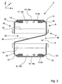
- Fig. 3 illustrates in a cross-sectional view of an embodiment of the first aspect of the present invention.
- Fig. 3 shows the support frame 4 having a first side 8 and a second side 10.
- the support frame extends in a longitudinal direction (i.e. in the y-direction.
- the support frame supports an endless carrier chain 6.
- the carrier chain 6 comprises an upper part 6a and a lower part 6b.
- the endless carrier chain comprises a conveyor belt comprising a polymeric material which may optionally be reinforced, such as by reinforcing wires or a reinforcing web.
- any other type of endless carrier chains may be applies as well, such as those defined in the claims.
- the support frame comprises a first main support element 16 supporting the upper part of the endless carrier chain at the first side 8 of the support frame; wherein said support frame comprises a second main support element 18 supporting the lower part of the endless carrier chain at the second side 10 of the support frame; wherein said support frame comprises a first auxiliary support element 20 supporting the upper part of the endless carrier chain at the second side 10 of the support frame; wherein said support frame comprises a second auxiliary support element 22 supporting the lower part of the endless carrier chain at the first side 8 of the support frame.
- Support struts 26 and 28 serves as supporting and strengthening the integrity of the support frame.
- the support frame comprises a shielding element 24 extending from the first side 8 of the support frame to the second side 10 of the support frame in an area A defined between the inner side 12a of the upper part of the endless carrier chain 6 and the inner side 12b of the lower part of the endless carrier chain 6.
- the shielding element 24 is arranged in such a way that the shielding element 24 itself, or said shielding element 24 in combination with said first main support element 16 and/or in combination with said second main support element 18 having an extension that blocks a direct access between any point P1 located on the inner side 12a of the upper part of the endless carrier chain 6 and a corresponding point P2 located on the inner side 12b of the lower part of the endless carrier chain, said point P2 being the most proximal point, in relation to the point P1, on the inner side 12b of the lower part of the endless carrier chain.
- the shielding element has a preferred Z-like form.
- openings 26 and 28 clearly provides for good access to the interior of the upper part of the conveyor system (via opening 28) as well as good access to the interior of the lower part of the conveyor system (via opening 26). Such good accesses are beneficial in cleaning processes.
- the same principle of the shielding element 24 applies.
- the rinsing liquid used such as water or detergent/water will by virtue of the shielding element by directed away from the lower part of the support frame and/or the lower part of the endless carrier chain so that these part will not be contaminated with dirty rinsing water.
- Fig. 1 shows in a cross-sectional view an example of a prior art conveyor system (the XMX system of Flexlink mentioned in the introduction of the present application.
- the prior art system of fig. 1 comprises a carrier frame which in turn comprises a first side part 106 and a second side part 108.
- the two side parts are spaced apart so that they together forms an upper longitudinal opening upon which the carrier chain 102 is supported, and a lower longitudinal opening supporting the lower carrier chain 104.
- the system of fig. 1 does not prevent debris from the upper part of the system to reach the lower part of the system. Further, the system of fig. 1 does not provide good access to the interior of the conveyor system.
- fig. 2 An improvement to the system of fig. 1 is illustrated in fig. 2 .
- This system corresponds to the XMY system of Flexlink mentioned in the introduction of the present application.
- Fig. 2 shows a conveyor system 200 comprising an upper part 220 and a lower part 210.
- the upper part of the endless carrier chain 202 is accommodated in an upper part of the support frame 220, whereas the lower part of the endless carrier chain 204 is accommodated in a lower part of the support frame 230.
- the upper part of the support frame and the lower part of the support frame are completely separated from each other except at specific points located along the longitudinal direction of the support frame, where the two parts are fastened to each other by brackets 214.
- the upper part of the support frame comprises two side walls 206,208 at a first side and a second side of the support frame, respectively.
- the upper part of the support frame thus comprises an opening at the top in which the endless carrier chain 202 is accommodated.
- the lower part of the support frame 230 has a profile defining an opposite V or U. That is, the lower part of the support frame of the system of fig. 2 is completely closed at the top, but comprises a longitudinal opening at the bottom, in which the lower part of the endless carrier chain 204 is accommodating.
- the prior art system of fig. 2 avoids the problem that debris originating from the upper part of the endless carrier chain deposits onto the lower part of the endless carrier chain.
- Fig. 4 shows a cross-sectional embodiment of a conveyor system according to the present invention.
- the conveyor system is provided with a gutter 30 for collecting debris and/or rinsing liquids originating from the upper part of the conveyor system and lead to the said gutter 30 by the shielding element 24.
- This embodiment of the system without the corresponding endless carrier chain, i.e. of the corresponding support frame, is depicted in fig. 5 in a perspective view.
- the system of fig. 3 and 4 as depicted shows presence of gliding means 15.
- the gliding means 15 provides a smooth surface upon which the endless carrier chain is supported and/or glides.
- the conveyor system may comprise, at one or more specific locations 23 along the first side of the support frame, a connection between the first main support element 16 and the second auxiliary support element 22. Such connections may also or alternatively in a correspondingly way be present at one or more specific locations 23 along the second side of the support frame.
- a Cartesian coordinate system is included to illustrate the various directions of a conveyor system in an intended use as defined in claim 1.
- the z-direction defines a vertical direction.
- the x-y-plane defines a horizontal plane.
- the longitudinal direction of the support frame accordingly extends along the y-direction "into and out of the paper".
- the present invention relates to a conveyor apparatus comprising a conveyor system according to the invention according to the first aspect of the present invention and drive means for moving the endless carrier chain relative to the support frame.
- the conveyor apparatus and the conveyor system according to the invention may be manufactured using materials and manufacturing processes and techniques well known in the art.
- a person skilled in the art of manufacturing conveyor systems and apparatuses will - on the basis of the present description and the appended claims - know how to manufacture the system and the apparatus according to the first and second aspect of the present invention, respectively.
Landscapes
- Engineering & Computer Science (AREA)
- Mechanical Engineering (AREA)
- Chain Conveyers (AREA)
- Framework For Endless Conveyors (AREA)
- Structure Of Belt Conveyors (AREA)
Claims (17)
- Système de convoyeur (2) comprenant une structure de support (4) et une chaîne de transport sans fin (6) ;
dans lequel ladite structure de support s'étend dans un sens longitudinal et comprend un premier côté (8) et un deuxième côté (10) ;
dans lequel ladite chaîne de transport sans fin (6) est disposée sur ladite structure de support (4);
dans lequel, dans une orientation destinée à l'utilisation dans laquelle la chaîne de transport sans fin (6) est disposée dans une orientation horizontale, ladite chaîne de transport (6) définit une partie supérieure (6a) mobile dans un sens par rapport à ladite structure de support ; et une partie inférieure (6b) mobile dans le sens opposé par rapport à ladite partie supérieure de ladite chaîne de transport ; ladite chaîne de transport sans fin possédant ainsi un côté intérieur (12) est un côté extérieur (14) ;
dans lequel ladite structure de support comprend un premier élément de support principal (16) supportant la partie supérieure de la chaîne de transport sans fin sur le premier côté (8) de la structure de support ;
dans lequel ladite structure de support comprend un deuxième élément de support principal (18) supportant la partie inférieure de la chaîne de transport sans fin sur le deuxième côté (10) de la structure de support ;
dans lequel ladite structure de support comprend un premier élément de support auxiliaire (20) supportant la partie supérieure de la chaîne de transport sans fin sur le deuxième côté (10) de la structure de support ;
dans lequel ladite structure de support comprend un deuxième élément de support auxiliaire (22) supportant la partie inférieure de la chaîne de transport sans fin sur le premier côté (8) de la structure de support ;
dans lequel ladite structure de support comprend un élément d'isolation (24) s'étendant du premier côté (8) de la structure de support au deuxième côté (10) de la structure de support dans une zone (A) définie entre le côté intérieur (12a) de la partie supérieure de la chaîne de transport sans fin (6) et le côté intérieur (12b) de la partie inférieure de la chaîne de transport sans fin (6) ; et
dans lequel ledit élément d'isolation (24) lui-même, ou le dit élément d'isolation (24) combiné avec ledit premier élément de support principal (16) et/ou combiné avec le deuxième élément de support principal (18) a une extension qui bloque un accès direct entre tout point P1 situé sur le côté intérieur (12a) de la partie supérieure de la chaîne de transport sans fin (6) et un point P2 correspondant situé sur le côté intérieur (12b) de la partie inférieure de la chaîne de transport sans fin, le dit point P2 étant le point le plus proximal, par rapport au point P1, sur le côté intérieur (12b) de la partie inférieure de la chaîne du transport sans fin;
caractérisé en ce que
le premier côté (8) de la structure de support (4) comprend une ouverture (26), s'étendant de préférence le long de la quasi-totalité du premier côté dans le sens longitudinal, ladite ouverture (26) fournissant un accès au côté intérieur (12b) de la partie inférieure (6b) de la chaîne de transport sans fin (6) ; ladite ouverture (26) étant définie par une géométrie du premier élément de support principal (16), de l'élément d'isolation (24) et du deuxième élément de support auxiliaire (22) ; et/ou
en ce que le deuxième côté (10) de la structure de support (4) comprend une ouverture (28) s'étendant de préférence le long de la quasi-totalité du deuxième côté dans le sens longitudinal, ladite ouverture (28) fournissant un accès au côté intérieur (12a) de la partie supérieure (6a) de la chaîne de transport sans fin (6) ; ladite ouverture (28) étant définie par la géométrie du deuxième élément de support principal (18), de l'élément d'isolation (24) et du premier élément de support auxiliaire (20). - Système de convoyeur selon la revendication 1, dans lequel le dit élément d'isolation (24) définit, au moins partiellement dans la zone A, une surface plane s'étendant dans une orientation inclinée, par rapport à un plan horizontal, du premier côté de la structure de support au deuxième côté de la structure de support.
- Système de convoyeur selon la revendication 1 ou 2, dans lequel le premier élément de support principal (16) est connecté au deuxième élément de support auxiliaire (22) à un ou plusieurs endroits spécifiques (23) le long du premier côté de la structure de support et/ou dans lequel le deuxième élément de support principal (18) est relié au premier élément de support auxiliaire (20) à un ou plusieurs endroits spécifiques (23) le long du deuxième côté de la structure de support.
- Système de convoyeur selon l'une quelconque des revendications 1 à 3, dans lequel une gouttière (30) est disposée sur le deuxième élément de support principal (18) pour la récupération de l'eau de rinçage dans une situation de rinçage, ladite gouttière (30) s'étendant dans un sens longitudinal de la structure de support (4).
- Système de convoyeur selon l'une quelconque des revendications 1 à 4, dans lequel une ou plusieurs entretoises supérieures transversales (32) sont disposées à des endroits prédéfinis le long du sens longitudinal de la structure de support (4) ; lesdites entretoises supérieures transversales (32) reliant le premier élément de support principal (16) du premier côté de la structure de support avec le premier élément de support auxiliaire (20) du deuxième côté de l'élément de support.
- Système de transport selon l'une quelconque des revendications 1 à 5, dans lequel une ou plusieurs entretoises inférieures transversales (34) sont disposées à des endroits prédéfinis le long du sens longitudinal de la structure de support (4) ; lesdites entretoises inférieures transversales (34) reliant le deuxième élément de support principal (18) du deuxième côté de la structure de support avec le deuxième élément de support auxiliaire (22) du premier côté de la structure de support.
- Système de convoyeur selon l'une quelconque des revendications 1 à 6, dans lequel le premier élément de support principal (16) du premier côté de la structure de support, l'élément d'isolation (24) et le deuxième élément de support principal (18) du deuxième côté de la structure de support sont formés de façon intégrale en une seule pièce.
- Système de convoyeur selon l'une quelconque des revendications 1 à 7, dans lequel le profil d'au moins une partie du groupe d'éléments comprenant le premier élément de support principal (16) du premier côté de la structure de support, l'élément d'isolation (24) et le deuxième élément de support principal (18) du deuxième côté de la structure de support, vu dans un sens transversal par rapport au sens longitudinal de la structure de support (4) présente une forme en Z.
- Système de convoyeur selon l'une quelconque des revendications 1 à 8 dans lequel la chaîne de transport sans fin est une chaîne de transport sélectionnée du groupe comprenant : un système de transport flexible, dans lequel la chaîne de transport sans fin comprend un nombre d'éléments s'interpénétrant reliés de façon flexible l'un a l'autre et formant une chaîne sans fin; une chaîne transporteuse comprenant un matériau polymère qui peut optionnellement être renforcé, tels que par des fils de renforcement ou une nervure de renforcement ; une chaîne à lamelles comprenant un nombre d'éléments lamellaires articulés de façon interpénétrante l'un contre l'autre sur un côté ; une chaîne de fil métallique comprenant un nombre de fils métalliques tissés ensemble ; un quelconque type de chaînes d'acier, tels que des chaînes d'acier ouvertes ou fermées.
- Système de convoyeur selon l'une quelconque des revendications 1 à 9, dans lequel un ou plusieurs des éléments : premier élément de support principal (16), deuxième élément de support principal (18), premier élément de support auxiliaire (20), deuxième élément de support auxiliaire (22), l'élément d'isolation (24), la gouttière (30), une ou plusieurs des entretoises supérieures transversales (32), une ou plusieurs des entretoises inférieures transversales (34), sont faits d'acier, tels que de l'acier inoxydable, de l'aluminium, ou un matériau polymère, tel qu'un plastique.
- Système de convoyeur selon l'une quelconque des revendications 1 à 10, comprenant en outre des moyens de brossage pour brosser la chaîne de transport sans fin (6) sur la surface extérieure (14a) sur la partie supérieure de la chaîne de transport sans fin (6) et/ou sur la surface extérieure (14b), sur la partie inférieure de la chaîne de transport sans fin (6).
- Système de convoyeur selon l'une quelconque des revendications 1 à 11, comprenant en outre des moyens de déviation de chaîne de transport pour dévier ou diriger ladite chaîne de transport sans fin (6) vers l'intérieur d'un conteneur de rinçage pour rincer la chaîne de transport sans fin (6) avec un liquide de rinçage.
- Système de convoyeur selon l'une quelconque des revendications 11 ou 12, dans lequel lesdits moyens de brossage et/ou moyens de déviation est/sont muni(s) de moyens d'engagement de brossage et/ou des moyens d'engagement de déviation de chaîne de transport pour engager/désengager de façon réversible lesdits moyens de brossage et/ou moyens de déviation, respectivement.
- Système de convoyeur comprenant deux ou plus systèmes de convoyeur selon l'une quelconque des revendications 1 à 13 disposés au-dessus des uns des autres, tels que 2,3, 4,5, 6,7 ou 8 systèmes de convoyeur arrangés les uns au-dessus des autres.
- Appareil de convoyage comprenant un système de convoyeur selon l'une quelconque des revendications 1 à 14 et des moyens d'entraînement pour entrainer la chaîne de transport sans fin par rapport à la structure de support (4).
- Utilisation d'un système de convoyeur selon l'une quelconque des revendications 1 à 14 ou d'un appareil deconvoyage selon la revendication 15 pour transporter un objet.
- Utilisation selon la revendication 16, dans laquelle l'objet est de la nourriture ou un précurseur de nourriture.
Priority Applications (1)
| Application Number | Priority Date | Filing Date | Title |
|---|---|---|---|
| PL11779333T PL2635511T3 (pl) | 2010-11-02 | 2011-10-26 | Pas transportowy |
Applications Claiming Priority (2)
| Application Number | Priority Date | Filing Date | Title |
|---|---|---|---|
| DKPA201000990A DK177306B1 (en) | 2010-11-02 | 2010-11-02 | Conveyor |
| PCT/DK2011/000118 WO2012059101A1 (fr) | 2010-11-02 | 2011-10-26 | Transporteur |
Publications (2)
| Publication Number | Publication Date |
|---|---|
| EP2635511A1 EP2635511A1 (fr) | 2013-09-11 |
| EP2635511B1 true EP2635511B1 (fr) | 2014-09-24 |
Family
ID=44910082
Family Applications (1)
| Application Number | Title | Priority Date | Filing Date |
|---|---|---|---|
| EP11779333.1A Active EP2635511B1 (fr) | 2010-11-02 | 2011-10-26 | Transporteur |
Country Status (16)
| Country | Link |
|---|---|
| US (1) | US8851277B2 (fr) |
| EP (1) | EP2635511B1 (fr) |
| JP (1) | JP5923096B2 (fr) |
| KR (1) | KR20130127438A (fr) |
| CN (1) | CN103189288B (fr) |
| AU (1) | AU2011325561B2 (fr) |
| BR (1) | BR112013007043B1 (fr) |
| CA (1) | CA2816110C (fr) |
| DK (1) | DK177306B1 (fr) |
| ES (1) | ES2526322T3 (fr) |
| MX (1) | MX339700B (fr) |
| MY (1) | MY170334A (fr) |
| NZ (1) | NZ610078A (fr) |
| PL (1) | PL2635511T3 (fr) |
| PT (1) | PT2635511E (fr) |
| WO (1) | WO2012059101A1 (fr) |
Families Citing this family (9)
| Publication number | Priority date | Publication date | Assignee | Title |
|---|---|---|---|---|
| US8662292B2 (en) * | 2011-09-26 | 2014-03-04 | Service Industries, LLC | Conveyor belt assembly |
| JP2016533998A (ja) * | 2013-09-18 | 2016-11-04 | フレックスリンク アーベー | ガイドレール |
| EP2998248B1 (fr) * | 2014-09-22 | 2017-03-01 | Avancon Sa | Système de convoyage |
| EP3237335A4 (fr) * | 2014-12-23 | 2018-11-14 | Effluent Free Desalination Corp. | Procédé et appareil de dessalement amélioré d'eau de mer sans production d'effluents |
| KR200485037Y1 (ko) * | 2016-06-29 | 2017-11-22 | 세창인터내쇼날(주) | 컨베이어용 프레임틀 |
| WO2019095001A1 (fr) * | 2017-11-17 | 2019-05-23 | Alan Lewis Fitzmaurice | Ensemble transporteur de macération sans fin doté d'un déflecteur de jus |
| CN107955870A (zh) * | 2018-01-26 | 2018-04-24 | 湖南高致精工机械有限公司 | 一种适用于履带铁齿工件的余热淬火装置 |
| CN109723086B (zh) * | 2019-03-05 | 2020-12-22 | 安徽省华腾农业科技有限公司经开区分公司 | 一种曲线段钢筋笼顶推装置用的磁力推送设备的使用方法 |
| CN114988017A (zh) * | 2022-06-17 | 2022-09-02 | 昌硕输送设备(无锡)有限公司 | 一种便于清洗的输送线结构 |
Family Cites Families (32)
| Publication number | Priority date | Publication date | Assignee | Title |
|---|---|---|---|---|
| US3848732A (en) * | 1972-05-01 | 1974-11-19 | Continental Can Co | Riveted modular conveyor |
| US3824067A (en) * | 1973-03-20 | 1974-07-16 | Lehara Inc Werner | Oven conveyor and method |
| US4013167A (en) * | 1975-05-21 | 1977-03-22 | Custom Fabricators, Inc. | Conveyor support structure |
| US3998321A (en) * | 1975-09-15 | 1976-12-21 | Schultz Edward D | Conveyor wash device |
| SE428201B (sv) * | 1980-02-14 | 1983-06-13 | Skf Ab | Transportor innefattande ett antal i ett endlost band efter varandra fogade kroppar anordnade att framdrivas och styras |
| SE8107357L (sv) * | 1981-12-09 | 1983-06-10 | Skf Ab | Transportor innefattande lettmonterade balksektioner |
| DE3437049A1 (de) * | 1983-10-11 | 1985-04-25 | Santrade Ltd., Luzern | Foerdereinrichtung |
| SE8405826L (sv) * | 1984-11-20 | 1986-05-21 | Skf Ab | Transportanordning med flerdelad transportorbalk |
| US5220989A (en) * | 1989-06-07 | 1993-06-22 | Texas A&M University | Modular tray accumulator system |
| US5186314A (en) * | 1990-09-28 | 1993-02-16 | Simplimatic Engineering Company | Conveyor system |
| WO1992011191A1 (fr) * | 1990-12-20 | 1992-07-09 | Ideas In Motion Pty. Ltd. | Systeme de transporteur modulaire |
| JPH057378U (ja) * | 1991-07-05 | 1993-02-02 | 株式会社クボタ | 作物選別装置 |
| US5178263A (en) * | 1991-11-27 | 1993-01-12 | International Paper Company | Modular track section for an endless conveyor |
| JP2562229Y2 (ja) * | 1993-03-23 | 1998-02-10 | 麒麟麦酒株式会社 | 低騒音型搬送コンベア |
| US5605219A (en) * | 1994-09-12 | 1997-02-25 | Avtec Industries, Inc. | Article conveyor system |
| JP3304695B2 (ja) * | 1995-07-07 | 2002-07-22 | 株式会社ダイフク | コンベヤフレーム |
| US5649616A (en) * | 1996-04-11 | 1997-07-22 | Stecklow; Richard L. | Conveyor chain cleaning apparatus |
| US5788056A (en) * | 1996-08-12 | 1998-08-04 | Tekno, Inc. | Conveyor frame with removable tracks retained by spring pins |
| US5860511A (en) | 1996-11-15 | 1999-01-19 | Rexnord Corporation | Conveyor guide rail supports |
| JP3801765B2 (ja) * | 1998-02-09 | 2006-07-26 | 松下電器産業株式会社 | リフロー炉 |
| US6401912B1 (en) * | 1999-10-26 | 2002-06-11 | Clarence L. Bandy, Jr. | Conveyor pan assembly with replaceable deck |
| SE516849C2 (sv) | 2000-07-05 | 2002-03-12 | Flexlink Components Ab | Glidlistanordning till transportör |
| US6422382B1 (en) * | 2000-09-01 | 2002-07-23 | Dorner Mfg. Corp. | Conveyor incorporating a modular frame construction |
| SE519179C2 (sv) * | 2001-06-13 | 2003-01-28 | Flexlink Components Ab | Transportör samt förbindningsstycke till transportörbalksidor |
| CN2487705Y (zh) * | 2001-06-14 | 2002-04-24 | 区永辉 | 一种防静电尘埃的履带输送线 |
| SE519706C2 (sv) * | 2001-08-03 | 2003-04-01 | Flexlink Components Ab | Arbetsmodul för anslutning till en huvudtransportör i ett konveyersystem innefattande en ändlös kedja, samt en transportenhet |
| SE521815C2 (sv) * | 2002-04-19 | 2003-12-09 | Flexlink Components Ab | Metod och ämne för tillverkning av ett krökt kurvelement, krökt kurvelement, kurvenhet innefattande ett krökt kurvelement samt transportbana innefattande en sådan kurvenhet. |
| US6848572B1 (en) * | 2003-11-10 | 2005-02-01 | Danville Automation Holdings Llc | Modular conveyor system |
| BRPI0515542A (pt) * | 2004-09-21 | 2008-07-29 | Vibre Tech Llc | aparelho e método de limpar transportador |
| PL379034A1 (pl) * | 2006-02-22 | 2007-09-03 | International Tobacco Machinery Poland Spółka Z Ograniczoną Odpowiedzialnością | Sposób i urządzenie do mycia taśm przenośników |
| US8430229B2 (en) * | 2007-09-14 | 2013-04-30 | Flexlink Components Ab | Lifting device for a conveyor system a conveyor system and a method |
| US8662292B2 (en) * | 2011-09-26 | 2014-03-04 | Service Industries, LLC | Conveyor belt assembly |
-
2010
- 2010-11-02 DK DKPA201000990A patent/DK177306B1/en not_active IP Right Cessation
-
2011
- 2011-10-26 BR BR112013007043-9A patent/BR112013007043B1/pt not_active IP Right Cessation
- 2011-10-26 WO PCT/DK2011/000118 patent/WO2012059101A1/fr not_active Ceased
- 2011-10-26 AU AU2011325561A patent/AU2011325561B2/en not_active Ceased
- 2011-10-26 CN CN201180051455.0A patent/CN103189288B/zh not_active Expired - Fee Related
- 2011-10-26 NZ NZ610078A patent/NZ610078A/en not_active IP Right Cessation
- 2011-10-26 MX MX2013004728A patent/MX339700B/es active IP Right Grant
- 2011-10-26 MY MYPI2013700630A patent/MY170334A/en unknown
- 2011-10-26 PL PL11779333T patent/PL2635511T3/pl unknown
- 2011-10-26 JP JP2013535280A patent/JP5923096B2/ja active Active
- 2011-10-26 ES ES11779333.1T patent/ES2526322T3/es active Active
- 2011-10-26 EP EP11779333.1A patent/EP2635511B1/fr active Active
- 2011-10-26 KR KR1020137009745A patent/KR20130127438A/ko not_active Ceased
- 2011-10-26 US US13/824,257 patent/US8851277B2/en active Active
- 2011-10-26 PT PT117793331T patent/PT2635511E/pt unknown
- 2011-10-26 CA CA2816110A patent/CA2816110C/fr active Active
Also Published As
| Publication number | Publication date |
|---|---|
| MY170334A (en) | 2019-07-18 |
| MX2013004728A (es) | 2013-07-12 |
| BR112013007043A2 (pt) | 2016-06-14 |
| JP2013545688A (ja) | 2013-12-26 |
| AU2011325561B2 (en) | 2015-03-12 |
| US20130180833A1 (en) | 2013-07-18 |
| KR20130127438A (ko) | 2013-11-22 |
| DK201000990A (en) | 2012-05-03 |
| WO2012059101A1 (fr) | 2012-05-10 |
| DK177306B1 (en) | 2012-11-12 |
| BR112013007043B1 (pt) | 2021-04-20 |
| PT2635511E (pt) | 2014-12-31 |
| CN103189288B (zh) | 2016-02-17 |
| ES2526322T3 (es) | 2015-01-09 |
| JP5923096B2 (ja) | 2016-05-24 |
| CA2816110A1 (fr) | 2012-05-10 |
| HK1183469A1 (zh) | 2013-12-27 |
| EP2635511A1 (fr) | 2013-09-11 |
| CN103189288A (zh) | 2013-07-03 |
| US8851277B2 (en) | 2014-10-07 |
| CA2816110C (fr) | 2019-03-19 |
| NZ610078A (en) | 2014-03-28 |
| PL2635511T3 (pl) | 2015-03-31 |
| AU2011325561A1 (en) | 2013-05-23 |
| MX339700B (es) | 2016-05-18 |
Similar Documents
| Publication | Publication Date | Title |
|---|---|---|
| EP2635511B1 (fr) | Transporteur | |
| US5316134A (en) | Conveyor guidetrack segment | |
| DE102013112713B4 (de) | Spülmaschine | |
| US20160229640A1 (en) | Conveyor chain support | |
| KR101648797B1 (ko) | 상자 자동 세척장치 | |
| CA1158578A (fr) | Ange metallique, et methode de fabrication connexe | |
| US9604789B2 (en) | Guide rail | |
| EP0201746B1 (fr) | Dispositif de nettoyage d'objets se déplaçant sur des bandes transporteuses | |
| EP1167248A1 (fr) | Convoyeur | |
| HK1183469B (en) | Conveyor | |
| RU2402475C2 (ru) | Уплотнительный щиток для конвейера | |
| CN212069838U (zh) | 一种计量器具周转箱全自动喷淋烘干机 | |
| CN110949928B (zh) | 烟草原料物流高架仓储系统 | |
| CN221069805U (zh) | 一种自动送料机 | |
| CN209506137U (zh) | 一种成品饲料流动除粉装置 | |
| CN212100605U (zh) | 一种具有自清洁功能的输送机 | |
| JPS628907A (ja) | 流体搬送装置 | |
| CN119750109A (zh) | 一种微动力导料槽 | |
| CN112407849A (zh) | 一种具有自清理功能的输送机械设备 | |
| JP2627210B2 (ja) | クリーンルーム用コンベヤ装置 | |
| IT1247095B (it) | Dispositivo di trasporto di elementi, ad estensione sostanzialmente orizzontale durante operazioni di verniciatura | |
| JPS62192198A (ja) | じゆうたん洗浄方法 | |
| DE8512960U1 (de) | Waschgerät zur Reinigung von auf Förderbahnen fortbewegten Werkstückträgern | |
| DE102016014578A1 (de) | Verfahren und Vorrichtung zum Trocknen von Trägern |
Legal Events
| Date | Code | Title | Description |
|---|---|---|---|
| PUAI | Public reference made under article 153(3) epc to a published international application that has entered the european phase |
Free format text: ORIGINAL CODE: 0009012 |
|
| 17P | Request for examination filed |
Effective date: 20130523 |
|
| AK | Designated contracting states |
Kind code of ref document: A1 Designated state(s): AL AT BE BG CH CY CZ DE DK EE ES FI FR GB GR HR HU IE IS IT LI LT LU LV MC MK MT NL NO PL PT RO RS SE SI SK SM TR |
|
| DAX | Request for extension of the european patent (deleted) | ||
| GRAP | Despatch of communication of intention to grant a patent |
Free format text: ORIGINAL CODE: EPIDOSNIGR1 |
|
| INTG | Intention to grant announced |
Effective date: 20140415 |
|
| GRAS | Grant fee paid |
Free format text: ORIGINAL CODE: EPIDOSNIGR3 |
|
| GRAA | (expected) grant |
Free format text: ORIGINAL CODE: 0009210 |
|
| AK | Designated contracting states |
Kind code of ref document: B1 Designated state(s): AL AT BE BG CH CY CZ DE DK EE ES FI FR GB GR HR HU IE IS IT LI LT LU LV MC MK MT NL NO PL PT RO RS SE SI SK SM TR |
|
| REG | Reference to a national code |
Ref country code: GB Ref legal event code: FG4D |
|
| REG | Reference to a national code |
Ref country code: CH Ref legal event code: EP |
|
| REG | Reference to a national code |
Ref country code: AT Ref legal event code: REF Ref document number: 688519 Country of ref document: AT Kind code of ref document: T Effective date: 20141015 |
|
| REG | Reference to a national code |
Ref country code: IE Ref legal event code: FG4D |
|
| REG | Reference to a national code |
Ref country code: DE Ref legal event code: R096 Ref document number: 602011010163 Country of ref document: DE Effective date: 20141106 |
|
| REG | Reference to a national code |
Ref country code: SE Ref legal event code: TRGR |
|
| REG | Reference to a national code |
Ref country code: CH Ref legal event code: NV Representative=s name: MICHELI AND CIE SA, CH Ref country code: PT Ref legal event code: SC4A Free format text: AVAILABILITY OF NATIONAL TRANSLATION Effective date: 20141217 |
|
| REG | Reference to a national code |
Ref country code: ES Ref legal event code: FG2A Ref document number: 2526322 Country of ref document: ES Kind code of ref document: T3 Effective date: 20150109 |
|
| REG | Reference to a national code |
Ref country code: NL Ref legal event code: T3 |
|
| PG25 | Lapsed in a contracting state [announced via postgrant information from national office to epo] |
Ref country code: LT Free format text: LAPSE BECAUSE OF FAILURE TO SUBMIT A TRANSLATION OF THE DESCRIPTION OR TO PAY THE FEE WITHIN THE PRESCRIBED TIME-LIMIT Effective date: 20140924 |
|
| REG | Reference to a national code |
Ref country code: NO Ref legal event code: T2 Effective date: 20140924 |
|
| REG | Reference to a national code |
Ref country code: EE Ref legal event code: FG4A Ref document number: E010010 Country of ref document: EE Effective date: 20141217 |
|
| REG | Reference to a national code |
Ref country code: LT Ref legal event code: MG4D |
|
| PG25 | Lapsed in a contracting state [announced via postgrant information from national office to epo] |
Ref country code: HR Free format text: LAPSE BECAUSE OF FAILURE TO SUBMIT A TRANSLATION OF THE DESCRIPTION OR TO PAY THE FEE WITHIN THE PRESCRIBED TIME-LIMIT Effective date: 20140924 Ref country code: CY Free format text: LAPSE BECAUSE OF FAILURE TO SUBMIT A TRANSLATION OF THE DESCRIPTION OR TO PAY THE FEE WITHIN THE PRESCRIBED TIME-LIMIT Effective date: 20140924 Ref country code: LV Free format text: LAPSE BECAUSE OF FAILURE TO SUBMIT A TRANSLATION OF THE DESCRIPTION OR TO PAY THE FEE WITHIN THE PRESCRIBED TIME-LIMIT Effective date: 20140924 Ref country code: RS Free format text: LAPSE BECAUSE OF FAILURE TO SUBMIT A TRANSLATION OF THE DESCRIPTION OR TO PAY THE FEE WITHIN THE PRESCRIBED TIME-LIMIT Effective date: 20140924 |
|
| REG | Reference to a national code |
Ref country code: GR Ref legal event code: EP Ref document number: 20140402544 Country of ref document: GR Effective date: 20150128 |
|
| REG | Reference to a national code |
Ref country code: PL Ref legal event code: T3 |
|
| PG25 | Lapsed in a contracting state [announced via postgrant information from national office to epo] |
Ref country code: RO Free format text: LAPSE BECAUSE OF FAILURE TO SUBMIT A TRANSLATION OF THE DESCRIPTION OR TO PAY THE FEE WITHIN THE PRESCRIBED TIME-LIMIT Effective date: 20140924 Ref country code: IS Free format text: LAPSE BECAUSE OF FAILURE TO SUBMIT A TRANSLATION OF THE DESCRIPTION OR TO PAY THE FEE WITHIN THE PRESCRIBED TIME-LIMIT Effective date: 20150124 Ref country code: SK Free format text: LAPSE BECAUSE OF FAILURE TO SUBMIT A TRANSLATION OF THE DESCRIPTION OR TO PAY THE FEE WITHIN THE PRESCRIBED TIME-LIMIT Effective date: 20140924 |
|
| REG | Reference to a national code |
Ref country code: DE Ref legal event code: R097 Ref document number: 602011010163 Country of ref document: DE |
|
| PG25 | Lapsed in a contracting state [announced via postgrant information from national office to epo] |
Ref country code: MC Free format text: LAPSE BECAUSE OF FAILURE TO SUBMIT A TRANSLATION OF THE DESCRIPTION OR TO PAY THE FEE WITHIN THE PRESCRIBED TIME-LIMIT Effective date: 20140924 |
|
| PG25 | Lapsed in a contracting state [announced via postgrant information from national office to epo] |
Ref country code: DK Free format text: LAPSE BECAUSE OF FAILURE TO SUBMIT A TRANSLATION OF THE DESCRIPTION OR TO PAY THE FEE WITHIN THE PRESCRIBED TIME-LIMIT Effective date: 20140924 Ref country code: BG Free format text: LAPSE BECAUSE OF NON-PAYMENT OF DUE FEES Effective date: 20150630 |
|
| PLBE | No opposition filed within time limit |
Free format text: ORIGINAL CODE: 0009261 |
|
| STAA | Information on the status of an ep patent application or granted ep patent |
Free format text: STATUS: NO OPPOSITION FILED WITHIN TIME LIMIT |
|
| 26N | No opposition filed |
Effective date: 20150625 |
|
| REG | Reference to a national code |
Ref country code: FR Ref legal event code: PLFP Year of fee payment: 5 |
|
| PG25 | Lapsed in a contracting state [announced via postgrant information from national office to epo] |
Ref country code: SI Free format text: LAPSE BECAUSE OF FAILURE TO SUBMIT A TRANSLATION OF THE DESCRIPTION OR TO PAY THE FEE WITHIN THE PRESCRIBED TIME-LIMIT Effective date: 20140924 |
|
| PG25 | Lapsed in a contracting state [announced via postgrant information from national office to epo] |
Ref country code: SM Free format text: LAPSE BECAUSE OF FAILURE TO SUBMIT A TRANSLATION OF THE DESCRIPTION OR TO PAY THE FEE WITHIN THE PRESCRIBED TIME-LIMIT Effective date: 20140924 |
|
| REG | Reference to a national code |
Ref country code: DE Ref legal event code: R082 Ref document number: 602011010163 Country of ref document: DE Representative=s name: HERNANDEZ, YORCK, DIPL.-ING., DE |
|
| PG25 | Lapsed in a contracting state [announced via postgrant information from national office to epo] |
Ref country code: HU Free format text: LAPSE BECAUSE OF FAILURE TO SUBMIT A TRANSLATION OF THE DESCRIPTION OR TO PAY THE FEE WITHIN THE PRESCRIBED TIME-LIMIT; INVALID AB INITIO Effective date: 20111026 Ref country code: MT Free format text: LAPSE BECAUSE OF FAILURE TO SUBMIT A TRANSLATION OF THE DESCRIPTION OR TO PAY THE FEE WITHIN THE PRESCRIBED TIME-LIMIT Effective date: 20140924 |
|
| REG | Reference to a national code |
Ref country code: FR Ref legal event code: PLFP Year of fee payment: 6 |
|
| REG | Reference to a national code |
Ref country code: FR Ref legal event code: PLFP Year of fee payment: 7 |
|
| REG | Reference to a national code |
Ref country code: FR Ref legal event code: PLFP Year of fee payment: 8 |
|
| PG25 | Lapsed in a contracting state [announced via postgrant information from national office to epo] |
Ref country code: AL Free format text: LAPSE BECAUSE OF FAILURE TO SUBMIT A TRANSLATION OF THE DESCRIPTION OR TO PAY THE FEE WITHIN THE PRESCRIBED TIME-LIMIT Effective date: 20140924 |
|
| REG | Reference to a national code |
Ref country code: DE Ref legal event code: R082 Ref document number: 602011010163 Country of ref document: DE Representative=s name: HERNANDEZ, YORCK, DIPL.-ING., DE Ref country code: DE Ref legal event code: R081 Ref document number: 602011010163 Country of ref document: DE Owner name: DORNER (M) SDN. BHD., SAYAN LEPAS, MY Free format text: FORMER OWNER: FLEXMOVE SYSTEM (M) SDN.BHD., BAYAN LEPAS, PENANG, MY Ref country code: DE Ref legal event code: R081 Ref document number: 602011010163 Country of ref document: DE Owner name: DORNER (M) SDN. BHD., BAYAN LEPAS, MY Free format text: FORMER OWNER: FLEXMOVE SYSTEM (M) SDN.BHD., BAYAN LEPAS, PENANG, MY |
|
| REG | Reference to a national code |
Ref country code: LU Ref legal event code: HC Owner name: DORNER (M) SDN. BHD.; MY Free format text: FORMER OWNER: FLEXMOVE SYSTEM (M) SDN.BHD. Effective date: 20190904 |
|
| REG | Reference to a national code |
Ref country code: NO Ref legal event code: CHAD Owner name: DORNER (M) SDN. BHD., MY |
|
| REG | Reference to a national code |
Ref country code: DE Ref legal event code: R082 Ref document number: 602011010163 Country of ref document: DE Representative=s name: HERNANDEZ, YORCK, DIPL.-ING., DE |
|
| REG | Reference to a national code |
Ref country code: CH Ref legal event code: PFA Owner name: DORNER (M) SDN. BHD., MY Free format text: FORMER OWNER: FLEXMOVE SYSTEM (M) SDN.BHD., MY |
|
| REG | Reference to a national code |
Ref country code: EE Ref legal event code: HC1A Ref document number: E010010 Country of ref document: EE |
|
| REG | Reference to a national code |
Ref country code: ES Ref legal event code: PC2A Owner name: DORNER (M) SDN. BHD. Effective date: 20191218 |
|
| REG | Reference to a national code |
Ref country code: FI Ref legal event code: PCE Owner name: DORNER (M) SDN. BHD. |
|
| REG | Reference to a national code |
Ref country code: NL Ref legal event code: HC Owner name: DORNER (M) SDN. BHD.; MY Free format text: DETAILS ASSIGNMENT: CHANGE OF OWNER(S), CHANGE OF OWNER(S) NAME; FORMER OWNER NAME: FLEXMOVE SYSTEM (M) SDN.BHD. Effective date: 20200108 |
|
| REG | Reference to a national code |
Ref country code: AT Ref legal event code: HC Ref document number: 688519 Country of ref document: AT Kind code of ref document: T Owner name: DORNER (M) SDN. BHD., MY Effective date: 20200204 |
|
| REG | Reference to a national code |
Ref country code: BE Ref legal event code: HC Owner name: DORNER (M) SDN. BHD.; MY Free format text: DETAILS ASSIGNMENT: CHANGE OF OWNER(S), CHANGEMENT DE NOM DU PROPRIETAIRE, CORRECTION; FORMER OWNER NAME: DONER (M) SDN. BHD. Effective date: 20200206 Ref country code: BE Ref legal event code: HC Owner name: DONER (M) SDN. BHD.; MY Free format text: DETAILS ASSIGNMENT: CHANGE OF OWNER(S), CHANGEMENT DE NOM DU PROPRIETAIRE; FORMER OWNER NAME: FLEXMOVE SYSTEM (M) SDN.BHD. Effective date: 20200120 |
|
| PG25 | Lapsed in a contracting state [announced via postgrant information from national office to epo] |
Ref country code: BG Free format text: LAPSE BECAUSE OF NON-PAYMENT OF DUE FEES Effective date: 20150630 |
|
| PGRI | Patent reinstated in contracting state [announced from national office to epo] |
Ref country code: BG Effective date: 20151230 |
|
| PGFP | Annual fee paid to national office [announced via postgrant information from national office to epo] |
Ref country code: NL Payment date: 20231026 Year of fee payment: 13 |
|
| PGFP | Annual fee paid to national office [announced via postgrant information from national office to epo] |
Ref country code: LU Payment date: 20231026 Year of fee payment: 13 |
|
| PGFP | Annual fee paid to national office [announced via postgrant information from national office to epo] |
Ref country code: GB Payment date: 20231024 Year of fee payment: 13 Ref country code: GR Payment date: 20231018 Year of fee payment: 13 |
|
| PGFP | Annual fee paid to national office [announced via postgrant information from national office to epo] |
Ref country code: ES Payment date: 20231110 Year of fee payment: 13 |
|
| PGFP | Annual fee paid to national office [announced via postgrant information from national office to epo] |
Ref country code: TR Payment date: 20231016 Year of fee payment: 13 Ref country code: SE Payment date: 20231023 Year of fee payment: 13 Ref country code: PT Payment date: 20231013 Year of fee payment: 13 Ref country code: NO Payment date: 20231018 Year of fee payment: 13 Ref country code: IT Payment date: 20231024 Year of fee payment: 13 Ref country code: IE Payment date: 20231018 Year of fee payment: 13 Ref country code: FR Payment date: 20231026 Year of fee payment: 13 Ref country code: FI Payment date: 20231026 Year of fee payment: 13 Ref country code: EE Payment date: 20231024 Year of fee payment: 13 Ref country code: DE Payment date: 20231027 Year of fee payment: 13 Ref country code: CZ Payment date: 20231025 Year of fee payment: 13 Ref country code: CH Payment date: 20231101 Year of fee payment: 13 Ref country code: BG Payment date: 20231026 Year of fee payment: 13 Ref country code: AT Payment date: 20231018 Year of fee payment: 13 |
|
| PGFP | Annual fee paid to national office [announced via postgrant information from national office to epo] |
Ref country code: PL Payment date: 20231017 Year of fee payment: 13 Ref country code: BE Payment date: 20231026 Year of fee payment: 13 |
|
| PGFP | Annual fee paid to national office [announced via postgrant information from national office to epo] |
Ref country code: MK Payment date: 20231017 Year of fee payment: 13 |
|
| REG | Reference to a national code |
Ref country code: DE Ref legal event code: R119 Ref document number: 602011010163 Country of ref document: DE |
|
| REG | Reference to a national code |
Ref country code: EE Ref legal event code: MM4A Ref document number: E010010 Country of ref document: EE Effective date: 20241031 |
|
| REG | Reference to a national code |
Ref country code: CH Ref legal event code: PL |
|
| REG | Reference to a national code |
Ref country code: SE Ref legal event code: EUG |
|
| REG | Reference to a national code |
Ref country code: NL Ref legal event code: MM Effective date: 20241101 |
|
| REG | Reference to a national code |
Ref country code: AT Ref legal event code: MM01 Ref document number: 688519 Country of ref document: AT Kind code of ref document: T Effective date: 20241026 |
|
| GBPC | Gb: european patent ceased through non-payment of renewal fee |
Effective date: 20241026 |
|
| PG25 | Lapsed in a contracting state [announced via postgrant information from national office to epo] |
Ref country code: FI Free format text: LAPSE BECAUSE OF NON-PAYMENT OF DUE FEES Effective date: 20241026 |
|
| PG25 | Lapsed in a contracting state [announced via postgrant information from national office to epo] |
Ref country code: DE Free format text: LAPSE BECAUSE OF NON-PAYMENT OF DUE FEES Effective date: 20250501 |
|
| PG25 | Lapsed in a contracting state [announced via postgrant information from national office to epo] |
Ref country code: GB Free format text: LAPSE BECAUSE OF NON-PAYMENT OF DUE FEES Effective date: 20241026 |
|
| PG25 | Lapsed in a contracting state [announced via postgrant information from national office to epo] |
Ref country code: NO Free format text: LAPSE BECAUSE OF NON-PAYMENT OF DUE FEES Effective date: 20241031 |
|
| PG25 | Lapsed in a contracting state [announced via postgrant information from national office to epo] |
Ref country code: LU Free format text: LAPSE BECAUSE OF NON-PAYMENT OF DUE FEES Effective date: 20241026 Ref country code: BE Free format text: LAPSE BECAUSE OF NON-PAYMENT OF DUE FEES Effective date: 20241031 Ref country code: NL Free format text: LAPSE BECAUSE OF NON-PAYMENT OF DUE FEES Effective date: 20241101 |
|
| PG25 | Lapsed in a contracting state [announced via postgrant information from national office to epo] |
Ref country code: PT Free format text: LAPSE BECAUSE OF NON-PAYMENT OF DUE FEES Effective date: 20250429 |
|
| PG25 | Lapsed in a contracting state [announced via postgrant information from national office to epo] |
Ref country code: FR Free format text: LAPSE BECAUSE OF NON-PAYMENT OF DUE FEES Effective date: 20241031 Ref country code: EE Free format text: LAPSE BECAUSE OF NON-PAYMENT OF DUE FEES Effective date: 20241031 |
|
| PG25 | Lapsed in a contracting state [announced via postgrant information from national office to epo] |
Ref country code: BG Free format text: LAPSE BECAUSE OF NON-PAYMENT OF DUE FEES Effective date: 20241026 Ref country code: GR Free format text: LAPSE BECAUSE OF NON-PAYMENT OF DUE FEES Effective date: 20250512 |
|
| PG25 | Lapsed in a contracting state [announced via postgrant information from national office to epo] |
Ref country code: CH Free format text: LAPSE BECAUSE OF NON-PAYMENT OF DUE FEES Effective date: 20241031 |
|
| PG25 | Lapsed in a contracting state [announced via postgrant information from national office to epo] |
Ref country code: AT Free format text: LAPSE BECAUSE OF NON-PAYMENT OF DUE FEES Effective date: 20241026 |
|
| PG25 | Lapsed in a contracting state [announced via postgrant information from national office to epo] |
Ref country code: CZ Free format text: LAPSE BECAUSE OF NON-PAYMENT OF DUE FEES Effective date: 20241026 |
|
| REG | Reference to a national code |
Ref country code: BE Ref legal event code: MM Effective date: 20241031 |
|
| PG25 | Lapsed in a contracting state [announced via postgrant information from national office to epo] |
Ref country code: SE Free format text: LAPSE BECAUSE OF NON-PAYMENT OF DUE FEES Effective date: 20241027 Ref country code: IT Free format text: LAPSE BECAUSE OF NON-PAYMENT OF DUE FEES Effective date: 20241026 |
|
| PG25 | Lapsed in a contracting state [announced via postgrant information from national office to epo] |
Ref country code: IE Free format text: LAPSE BECAUSE OF NON-PAYMENT OF DUE FEES Effective date: 20241026 |
|
| REG | Reference to a national code |
Ref country code: ES Ref legal event code: FD2A Effective date: 20251204 |
|
| PG25 | Lapsed in a contracting state [announced via postgrant information from national office to epo] |
Ref country code: ES Free format text: LAPSE BECAUSE OF NON-PAYMENT OF DUE FEES Effective date: 20241027 |