EP2635512B1 - Fördersystem, förderband und verfahren dafür unter verwendung von beschleunigungsmessern - Google Patents
Fördersystem, förderband und verfahren dafür unter verwendung von beschleunigungsmessern Download PDFInfo
- Publication number
- EP2635512B1 EP2635512B1 EP11838439.5A EP11838439A EP2635512B1 EP 2635512 B1 EP2635512 B1 EP 2635512B1 EP 11838439 A EP11838439 A EP 11838439A EP 2635512 B1 EP2635512 B1 EP 2635512B1
- Authority
- EP
- European Patent Office
- Prior art keywords
- conveyor
- acceleration
- measurements
- belt
- accelerations
- Prior art date
- Legal status (The legal status is an assumption and is not a legal conclusion. Google has not performed a legal analysis and makes no representation as to the accuracy of the status listed.)
- Active
Links
Images


Classifications
-
- B—PERFORMING OPERATIONS; TRANSPORTING
- B65—CONVEYING; PACKING; STORING; HANDLING THIN OR FILAMENTARY MATERIAL
- B65G—TRANSPORT OR STORAGE DEVICES, e.g. CONVEYORS FOR LOADING OR TIPPING, SHOP CONVEYOR SYSTEMS OR PNEUMATIC TUBE CONVEYORS
- B65G43/00—Control devices, e.g. for safety, warning or fault-correcting
-
- B—PERFORMING OPERATIONS; TRANSPORTING
- B65—CONVEYING; PACKING; STORING; HANDLING THIN OR FILAMENTARY MATERIAL
- B65G—TRANSPORT OR STORAGE DEVICES, e.g. CONVEYORS FOR LOADING OR TIPPING, SHOP CONVEYOR SYSTEMS OR PNEUMATIC TUBE CONVEYORS
- B65G15/00—Conveyors having endless load-conveying surfaces, i.e. belts and like continuous members, to which tractive effort is transmitted by means other than endless driving elements of similar configuration
-
- B—PERFORMING OPERATIONS; TRANSPORTING
- B65—CONVEYING; PACKING; STORING; HANDLING THIN OR FILAMENTARY MATERIAL
- B65G—TRANSPORT OR STORAGE DEVICES, e.g. CONVEYORS FOR LOADING OR TIPPING, SHOP CONVEYOR SYSTEMS OR PNEUMATIC TUBE CONVEYORS
- B65G43/00—Control devices, e.g. for safety, warning or fault-correcting
- B65G43/02—Control devices, e.g. for safety, warning or fault-correcting detecting dangerous physical condition of load carriers, e.g. for interrupting the drive in the event of overheating
-
- B—PERFORMING OPERATIONS; TRANSPORTING
- B65—CONVEYING; PACKING; STORING; HANDLING THIN OR FILAMENTARY MATERIAL
- B65G—TRANSPORT OR STORAGE DEVICES, e.g. CONVEYORS FOR LOADING OR TIPPING, SHOP CONVEYOR SYSTEMS OR PNEUMATIC TUBE CONVEYORS
- B65G43/00—Control devices, e.g. for safety, warning or fault-correcting
- B65G43/06—Control devices, e.g. for safety, warning or fault-correcting interrupting the drive in case of driving element breakage; Braking or stopping loose load-carriers
-
- B—PERFORMING OPERATIONS; TRANSPORTING
- B65—CONVEYING; PACKING; STORING; HANDLING THIN OR FILAMENTARY MATERIAL
- B65G—TRANSPORT OR STORAGE DEVICES, e.g. CONVEYORS FOR LOADING OR TIPPING, SHOP CONVEYOR SYSTEMS OR PNEUMATIC TUBE CONVEYORS
- B65G23/00—Driving gear for endless conveyors; Belt- or chain-tensioning arrangements
- B65G23/22—Arrangements or mountings of driving motors
- B65G23/23—Arrangements or mountings of driving motors of electric linear motors
Definitions
- the invention relates generally to power-driven conveyors conveying articles and more particularly to conveyor systems using accelerometers to measure the acceleration of a conveyor conveying articles.
- a conveyor such as a conveyor belt
- smooth, linear motion of the conveyor is important in many applications, such as, for example, transporting passengers, manufacturing extrusions, and conveying unstable products subject to tipping upright.
- many variables cause the motion of conveyor belts not to be smooth. These variables include, but are not limited to, fluctuations in the belt's drive train, resonances in the conveyor belt, resonances in other coupled systems, and fluctuating loading caused by people walking over the surface of the belt.
- accelerometers are permanently affixed to devices or temporarily affixed using magnetic mounts, clips, or similar methods. Multiple accelerometers located throughout a mechanical device provide desirable local information of the device, but are prohibitive because of cost and physical constraints, such as mounting and routing of wires. Thus, there is a need for economically measuring and analyzing the wear characteristics of mechanical systems to predict failures.
- WO 2010/079764 A1 discloses a conveyor belt according to the preamble of claim 1 which is provided with a plurality of rollers, a detection part for detecting the state of the rollers, and a processing unit which is connected to the detection part and processes output signals from the detection part.
- One version of a conveyor system embodying features of the invention comprises a conveyor conveying articles in a conveying direction and an accelerometer embedded in the conveyor to make measurements of accelerations of the conveyor.
- a conveyor system comprises the technical features of claim 1.
- a method comprises the technical features of claim 10.
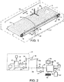
- FIG. 1 One version of a conveyor system embodying features of the invention is shown in FIG. 1 .
- a conveyor shown in this example as a conveyor belt 10 supported on a carryway 60, carries articles 12 through a process 11 in a conveying direction 13 on an outer conveying surface 22 along a carryway segment 15 of the belt's endless conveying path. At the end of the carryway, the articles are conveyed off the conveyor belt. After rounding drive sprockets 18, the conveyor belt 10 follows a return segment 17 on its way back around idle sprockets 20 to the carryway segment 15. Both the drive and idle sprockets are mounted on shafts 68 (only idle shaft shown in FIG. 1 ).
- One or more accelerometers 24 embedded in the belt 10 make measurements of accelerations in the belt.
- embedded is used in a broad sense to encompass any installation of an accelerometer in a conveyor.
- embedded accelerometers include accelerometers mounted on or in, molded into, inserted into, laminated in, welded to, bonded to, or otherwise rigidly connected to the advancing conveyor.
- the accelerometers 24 may be single-axis accelerometers sensing the component of local belt acceleration along an x-axis, for example, parallel to the conveying direction 13; a two-axis accelerometer sensing the components of acceleration along the x-axis and a y-axis perpendicular to the x-axis, for example, across the width of the conveyor belt; or a three-axis accelerometer sensing three orthogonal components of local acceleration, for example, along the x- and y-axes and along a z-axis extending through the thickness of the conveyor belt.
- belt accelerations along the x-axis would be of most interest and more susceptible to control, but accelerations along the other axes may be of interest as well.
- an accelerometer sensing accelerations along the z-axis, or even along the x-axis, could be used to detect the impact of an article dropped onto the conveyor belt.
- accelerometer technologies include piezoelectric, piezoresistive, and capacitive.
- MEMS micro-electro-mechanical-system
- FIG. 1 which shows a modular plastic conveyor belt loop constructed of rows of hinged modules, the accelerometers 24 are spaced apart regularly at locations along the length of the belt and across its width.
- each accelerometer 24 is connected to a logic circuit 28 in the conveyor belt 10.
- Each logic circuit may be realized by a programmed microcontroller or by hardwired logic elements. Conventional signal-conditioning circuit components, such as buffers, amplifiers, analog-to-digital converters, and multiplexers, may be interposed between the accelerometer and the logic circuit.
- the logic circuit may also include a unique address or other identifying indicia to correlate the response of each accelerometer with a specific position on the conveyor belt. The identifying indicia and the accelerometer's measurements may be stored in one or more memory elements 29.
- the transmitter may be a wireless RF transmitter transmitting wirelessly via an antenna 34 over a wireless communication link 36 or over an ohmic connection 38 between a conductive contact 40 on the outside of the belt 10 and a brush 42 in conveyor structure along the side of the belt, as in FIG. 1 .
- a receiver 33 may also be connected to the logic circuit to receive command and control signals from a remote controller 44, i.e., a controller not located on or in the conveyor belt.
- a remote controller 44 i.e., a controller not located on or in the conveyor belt.
- Other transmitter-receiver technologies such as optical or infrared, for example, may be used. All the components embedded in the belt may be powered by a power source 45, such as one or more battery cells, housed together in a cavity in the belt.
- the power source 45 may be an energy harvester harvesting energy from vibratory motion or articulation of the conveyor, thermal gradients, or other energy-producing effects inherent in the process or conveyance.
- the embedded power source 45 may alternatively be powered by induction or by RF charging as it recirculates past an external charging device 49, as in FIG. 1 .
- a remote receiver 46 receives the measurement signal 30 via an antenna 48 over the wireless communication link 36 or over the ohmic connection 38 from the receiver 33 embedded in the conveyor belt.
- the receiver 46 sends the measurement signal to the remote controller 44.
- a transmitter 47 connected between the controller 44 and the antenna 48 or the ohmic connection 38 may be used to send command and control signals to the belt-borne accelerometer circuits.
- An operator input device 50 connected to the controller 44 may be used to select accelerometer or alarm settings or data to be displayed.
- the controller 44 may also be used to stop or control the speed of a motor 52 driving the main drive sprockets 18, to control intermediate drives 62, or to activate a damper 64 acting on the conveyor belt itself.
- a video display 54 may be used to monitor system operating conditions and settings or to display alarm conditions.
- a more clearly visible or audible alarm 56 may also be used by the controller to warn of irregularities in the process.
- the controller may be a programmable logic controller, a laptop, a desktop, or any appropriate computer device
- the accelerometer 24 embedded in the belt 10 is used to damp accelerations in the belt. Its measurements of acceleration 30 are routed over the communication link 36 to the controller 44.
- the controller using wireless or copper control lines 61, applies damping to the drive shaft 68' of the conveyor in response to unwanted accelerations measured by the accelerometer. Damping is applied to the drive shaft by a rotational damper 70 controlled by the controller in a closed-loop control system to compensate for speed changes caused by vibrations, resonances, stick-slip, chordal action, imbalance, run-out, or other conditions causing regular or intermittent speed variations.
- FIG. 4 shows a similar closed-loop control system, except that the rotational damper 70 operates on the idle shaft 68 to apply damping, such as conventional speed-change damping, back tension, or controlled braking, at that point along the conveying path.
- FIGS. 5 and 5A depict linear damping applied to the conveyor belt 10 at positions along the carryway path 15. Acceleration measurements made by the accelerometers 24 are transmitted over the communications link 36 to the controller 44. Responding to the acceleration measurements, the controller activates linear dampers 72, which act directly on the conveyor belt 10. An actuator 74 associated with the linear damper 72 receives the control signal 61 from the controller to increase and decrease or otherwise modulate the pressure applied by the damper against the outer surface 22 of the conveyor belt 10.
- the linear damper 72 in the form of a movable pad, forms a clamp with the carryway 60 to apply a clamping force against the belt 10 and damp undesired accelerations. Like a modular plastic conveyor belt and a carryway, the clamping pad may be made of a viscoelastic material.
- the linear dampers can be applied intermittently along the carryway path segment 15.
- FIGS. 6 and 6A depict a similar linear damping system using magnetic or electromagnetic forces.
- the belt 10', the carryway 60', or both are made of a viscoelastic material.
- the clamping force is accomplished using magnets 73, permanent or electromagnetic.
- Permanent magnets or electromagnets 73 outside the belt act on ferrous or other magnetically attractive materials or magnets inside the belt 10' to generate a clamping force between the belt and the carryway.
- ferrous or other magnetically attractive materials outside the belt act on permanent magnets or electromagnets inside the belt to generate a clamping force.
- the controller 44 modulates the electromagnetic force or the position of the fixed attractive material to obtain the desired damping characteristic.
- FIGS. 7 and 7A Another form of damping acting on the conveyor belt itself is shown in FIGS. 7 and 7A .
- the entire conveyor belt 10', or portions of it, are made of an electrically conductive material.
- Magnetic field generators 76 disposed along the length of the conveyor belt 10' produce a magnetic field through which the belt passes. Eddy currents are induced in the conductive portions of the belt.
- the eddy currents produce an induced magnetic field that, according to Lenz's law, opposes the direction of the motion causing the induced field, i.e., the motion of the belt in the conveying direction 13. Consequently, the interaction of the inducing and induced magnetic fields results in a damping force applied to the conveyor belt 10' opposite to the conveying direction 13.
- the magnetic field generators are eddy-current dampers. They may be permanent magnets whose distance from the belt may be controlled by the controller 44 to adjust the magnitude of the fields and the damping force or electromagnets whose field strength can be electronically controlled by the controller.
- a similar form of damping is realized by making the conveyor belt 10', or portions of it, out of a ferrous or magnetically attractive material.
- the magnetic field generators 76 disposed along the length of the conveyor belt 10' act on the ferrous or magnetically attractive materials in the belt to create a force generally opposing the motion of the belt and so providing damping.
- the controller controls the operation of intermediate drives 62 engaged with the conveyor belt 10 at spaced apart positions along the carryway.
- the intermediate drives serve as dampers to damp unwanted belt accelerations. They can also serve as auxiliary drives to help the conveyor's main drive 78 advance the belt forward. This dual function is especially useful in long conveyors.
- the controller sends control signals 61 to each of the intermediate drives in response to acceleration measurements from the accelerometers 24 to damp unwanted accelerations in belt motion.
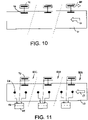
- Intermediate rotational dampers converting the linear motion of the belt surface to rotational motion may be similarly used as in FIG. 10 .
- the linear motion 13 of the belt 10 is converted to rotational motion via engagement with a circular engaging element 79, which may be a friction disk or a tire frictionally engaging the belt surface or a sprocket mechanically engaging mating drive structure in the belt.
- the circular engaging element 79 co-acts with an associated damper 70, which may provide viscous-fluid damping, eddy-current damping, magnetic damping, frictional damping, electric-motor damping, or regenerative damping with an electric generator providing power 80 back to the conveyor system.
- the main conveyor drive 78 is controlled directly in response to the belt-acceleration feedback provided by the accelerometers 24.
- the system's forcing function i.e., the belt drive 78
- Acceleration measurements 30 from the accelerometers 24 are transmitted to the controller 44 over the communications link 36.
- the controller produces a control signal 61 that compensates for the unwanted accelerations and applies the signal to the main drive 78, in this example, a variable-frequency motor drive.
- One moving accelerometer can be used to replace multiple stationary accelerometers and can provide finer-resolution data, which the controller 44 can use to perform failure-trend analysis of the process equipment in which the conveyor is installed and of other proximate devices, such as conveyor components, particularly at the infeed and discharge boundaries, and schedule the necessary maintenance.
- the controller can use the accelerometer-based data for protective control, such as shutting down the process, stopping the conveyor motor 52, or sounding alarms 56, as already described with reference to FIG. 2 , if excessive vibration or other out-of-range speed fluctuations are sensed. In this way, the system provides both remedial and prophylactic protection of the conveyor system and the entire process.
- FIG. 11 shows a plurality of controllers 44 with receivers 46 distributed along the length of the conveyor at fixed locations in individual control zones 82A-C.
- sensing in the receiver's zone is switched to the in-range accelerometer or accelerometers now local to that receiver.
- the controller coupled to that receiver uses the measurements of the local accelerometer or accelerometers in the receiver's zone to control an associated damper 70 in that zone in a closed-loop damping control system.
- an accelerometer advances past the zone of one local receiver and into the next zone, it is passed off to the receiver and the controller in the next zone.
- the accelerometer then becomes local to the controller controlling the damping in the next zone downstream.
- This distributed control system is especially useful in long conveyors.
- the damper control may be operated in an on/off or otherwise modulated fashion.
- the damping can vary linearly or nonlinearly with belt speed.
- the distributed control system of FIG. 11 is described as using an individual controller in each zone, a single controller receiving data from the receivers in all the zones and controlling all the dampers could be used instead.
Landscapes
- Engineering & Computer Science (AREA)
- Mechanical Engineering (AREA)
- Control Of Conveyors (AREA)
- Escalators And Moving Walkways (AREA)
Claims (14)
- Fördersystem, umfassend:Einen Förderer mit einem Förderband (10, 10'), um Artikel (12) in einer Förderrichtung (13) entlang eines Förderwegs zu fördern;einen in das Förderband (10) eingebetteten Beschleunigungsmesser (24), um Messungen von Beschleunigungen des Förderers vorzunehmen;ein Steuergerät (44), das die Messungen verarbeitet; gekennzeichnet durch einen vom Steuergerät (44) gesteuerten Dämpfer (64), um Beschleunigungen des Förderers als Reaktion auf die Messungen der Beschleunigung zu dämpfen.
- Fördersystem wie in Anspruch 1 beansprucht, das ferner einen Sender (33), der in das Förderband (10, 10') eingebettet ist, und einen Empfänger (46) extern des Förderers umfasst, wobei der Sender die vom Beschleunigungsmesser vorgenommenen Messungen von Beschleunigungen an den Empfänger sendet.
- Fördersystem wie in Anspruch 1 beansprucht, wobei der Dämpfer (64) ein linearer Dämpfer (72) ist, der eine Kraft gegen den Förderer anwendet, um Beschleunigungen des Förderers zu dämpfen.
- Fördersystem nach Anspruch 3, das ferner einen Fahrweg (60) umfasst, der den Förderer trägt; und
wobei der lineare Dämpfer eine bewegliche Platte einschließt, die dem Förderer gegenüber dem Fahrweg (60) zugewandt ist, wobei sich die Platte bewegt, um den Förderer gegen den Fahrweg zu klemmen, um Beschleunigungen zu dämpfen. - Fördersystem wie in Anspruch 3, wobei:a) der Förderer magnetisch anziehendes Material einschließt, wobei das Fördersystem ferner einen Fahrweg (60') umfasst, der den Förderer stützt, und wobei der lineare Dämpfer (72) einen vom Steuergerät (44) betätigten Magnet (73) einschließt, um den Förderer gegen den Fahrweg (60') anzuziehen, um Beschleunigungen zu dämpfen; oderb) wobei der Förderer ferner einen Fahrweg (60') umfasst, der den Förderer stützt, wobei der Fahrweg magnetisch anziehendes Material einschließt, und wobei der lineare Dämpfer (72) einen oder mehrere Magnete (73) im Förderer einschließt, die vom Steuergerät betätigt werden, um den Fahrweg gegen den Förderer anzuziehen, um Beschleunigungen zu dämpfen.
- Fördersystem wie in Anspruch 1, wobei:a) zumindest ein Teil des Förderers elektrisch leitend ist und wobei der Dämpfer (64) einen Magnetfeldgenerator (76) einschließt, der Wirbelströme im elektrisch leitenden Teil des Förderers induziert, um Beschleunigungen des Förderers zu dämpfen; oderb) wobei zumindest ein Teil des Förderers aus einen magnetisch anziehenden Materials hergestellt ist und wobei der Dämpfer (64) einen Magnetfeldgenerator (76) einschließt, der ein Magnetfeld erzeugt, das sich der Bewegung des Förderers in der Förderrichtung (13) entgegensetzt, um Beschleunigungen zu dämpfen.
- Fördersystem wie in Anspruch 1, das ferner einen Antrieb (62) zur Steuerung der Geschwindigkeit des Förderers in der Förderrichtung (13) umfasst, wobei das Steuergerät (44) die Geschwindigkeit des Förderers als Reaktion auf die Beschleunigungsmessungen einstellt, um Beschleunigungen des Förderers zu dämpfen.
- Fördersystem wie in Anspruch 1, wobei der Dämpfer (64) ein Rotationsdämpfer (70) ist, der ein Kupplungselement einschließt, das den Förderer kuppelt, um die lineare Bewegung des Förderers in der Förderrichtung in Rotationsbewegung umzuwandeln.
- Fördersystem wie in Anspruch 1, das eine Vielzahl von Beschleunigungsmessern (24) umfasst, die in das Förderband (10, 10') in beabstandeten Positionen eingebettet sind, wobei jeder Messungen der lokalen Beschleunigung des Förderers vornimmt.
- Verfahren zur Messung der Beschleunigung eines Förderers, umfassend:Antreiben eines Förderers, der ein Förderband (10, 10') mit zumindest einem eingebetteten Beschleunigungsmesser (24) aufweist, in eine Förderrichtung (13);Vornehmen von Messungen der Beschleunigung des Förderers mit dem zumindest einen eingebetteten Beschleunigungsmesser (24); gekennzeichnet durchSteuern der Bewegung des Förderers in der Förderrichtung als Reaktion auf die Messungen der Beschleunigung.
- Verfahren nach Anspruch 10, wobei das Vornehmen von Messungen der Beschleunigung das Vornehmen von Messungen an einer Vielzahl von Positionen eingebetteter Beschleunigungsmesser (24) entlang der Länge des Förderbandes (10, 10') umfasst.
- Verfahren nach Anspruch 10, wobei das Steuern der Bewegung des Förderers umfasst:a) Dämpfen der Beschleunigung des Förderers als Reaktion auf die Beschleunigungsmessungen;b) Dämpfen der Beschleunigung des Förderers als Reaktion auf die Messungen der Beschleunigung und ferner das Dämpfen der Beschleunigung des Förderers an einer Vielzahl von Dämpfungspositionen entlang der Länge des Förderers umfassend;c) Justieren der Geschwindigkeit des Förderers als Reaktion auf die Beschleunigungsmessungen; oderd) Stoppen des Förderers wann immer die Beschleunigungsmessungen einen vorbestimmten Level überschreiten.
- Verfahren nach Anspruch 10, das ferner das Erkennen des Aufpralls eines auf den Förderer gefallenen Artikels anhand der Beschleunigungsmessungen umfasst.
- Verfahren nach Anspruch 10, wobei der Förderer durch eine Verarbeitungseinrichtung angetrieben wird und ferner da Analysieren eines Fehlertrends der Verarbeitungseinrichtung anhand der Beschleunigungsmessungen des Förderers umfasst.
Applications Claiming Priority (2)
| Application Number | Priority Date | Filing Date | Title |
|---|---|---|---|
| US40915510P | 2010-11-02 | 2010-11-02 | |
| PCT/US2011/056511 WO2012060999A1 (en) | 2010-11-02 | 2011-10-17 | Conveyor system, belt, and method using accelerometers |
Publications (3)
| Publication Number | Publication Date |
|---|---|
| EP2635512A1 EP2635512A1 (de) | 2013-09-11 |
| EP2635512A4 EP2635512A4 (de) | 2017-09-13 |
| EP2635512B1 true EP2635512B1 (de) | 2022-06-29 |
Family
ID=46024764
Family Applications (1)
| Application Number | Title | Priority Date | Filing Date |
|---|---|---|---|
| EP11838439.5A Active EP2635512B1 (de) | 2010-11-02 | 2011-10-17 | Fördersystem, förderband und verfahren dafür unter verwendung von beschleunigungsmessern |
Country Status (7)
| Country | Link |
|---|---|
| US (1) | US9227791B2 (de) |
| EP (1) | EP2635512B1 (de) |
| JP (1) | JP2014500837A (de) |
| KR (1) | KR20130100181A (de) |
| CN (1) | CN103180231B (de) |
| DK (1) | DK2635512T3 (de) |
| WO (1) | WO2012060999A1 (de) |
Cited By (2)
| Publication number | Priority date | Publication date | Assignee | Title |
|---|---|---|---|---|
| EP4501820A1 (de) * | 2023-08-03 | 2025-02-05 | Ashworth Bros., Inc. | System zur überwachung des betriebs eines förderbandes |
| US12545525B2 (en) | 2023-08-03 | 2026-02-10 | Ashworth Bros., Inc. | Conveyor belt operation monitoring system |
Families Citing this family (28)
| Publication number | Priority date | Publication date | Assignee | Title |
|---|---|---|---|---|
| US9434545B2 (en) | 2010-11-02 | 2016-09-06 | Laitram, L.L.C. | Belt conveyors and viscoelastic dampers and methods for damping conveyor belts |
| CH707879A1 (de) | 2013-04-11 | 2014-10-15 | Ferag Ag | Regelung von Antrieben von Förderabschnitten eines Fördersystems. |
| KR20160145683A (ko) * | 2014-04-17 | 2016-12-20 | 라이트람, 엘엘씨 | 벨트 컨베이어, 점탄성 댐퍼, 및 컨베이어 벨트 감쇠 방법 |
| JP6164182B2 (ja) * | 2014-09-16 | 2017-07-19 | Jfeスチール株式会社 | ベルトコンベアの異常検知方法 |
| US10118802B2 (en) | 2014-10-31 | 2018-11-06 | Otis Elevator Company | Structural health monitoring of an escalator drive system |
| JP6660937B2 (ja) * | 2015-03-18 | 2020-03-11 | 株式会社日立ハイテクノロジーズ | 点検デバイス |
| CN104843423B (zh) * | 2015-04-27 | 2017-05-10 | 浙江大学 | 洗衣机离合器之离合轴的自动上料装置 |
| CN106228580B (zh) * | 2016-07-29 | 2019-03-05 | 李铮 | 一种基于视频分析的物料检测、节能方法及系统 |
| CN107421833B (zh) * | 2017-05-27 | 2023-03-28 | 中国矿业大学 | 一种提升容器衬板的自检测装置及检测方法 |
| KR102394574B1 (ko) * | 2017-07-11 | 2022-05-04 | 현대자동차 주식회사 | 스마트 태그 모니터링 시스템 및 그 방법 |
| EP3658477B1 (de) | 2017-07-26 | 2023-09-20 | Dematic Corp. | Verfahren und system zur überwachung der sortierungsleistung |
| WO2019045043A1 (ja) * | 2017-09-01 | 2019-03-07 | 株式会社椿本チエイン | 異常検知システム、異常検知装置、異常検知方法、コンピュータプログラム、及びチェーン |
| US10488282B2 (en) * | 2017-11-08 | 2019-11-26 | Rockwell Automation Technologies, Inc. | System and method for monitoring installation and health of belt driven motor/drive applications |
| DE102018110170A1 (de) | 2018-04-27 | 2019-10-31 | Voith Patent Gmbh | Transponder für einen Fördergurt eines Gurtförderers |
| DE102018110167A1 (de) | 2018-04-27 | 2019-10-31 | Voith Patent Gmbh | Fördergurt mit Sensoren und/oder Transpondern und Verfahren zur Montage von Sensoren und/oder Transpondern im Fördergurt |
| CN109748036B (zh) * | 2018-12-21 | 2020-09-29 | 明基材料有限公司 | 偏光片自动收料装置及方法 |
| DE102019101698A1 (de) * | 2019-01-24 | 2020-07-30 | Voith Patent Gmbh | Gurtförderer und Trommel für einen Gurtförderer |
| DE102019105203A1 (de) * | 2019-03-01 | 2020-09-03 | Schaeffler Technologies AG & Co. KG | Vorrichtung und Verfahren zum Bestimmen einer Geschwindigkeit oder Beschleunigung eines elektrisch leitfähigen Objekts, sowie System |
| CN109941698B (zh) * | 2019-04-03 | 2020-08-18 | 武汉科技大学 | 一种考虑疲劳破坏的带式输送机速度调节方法 |
| CN110596119A (zh) * | 2019-09-03 | 2019-12-20 | 佛山科学技术学院 | 一种电路板元器件检测装置 |
| US11034551B2 (en) * | 2019-11-15 | 2021-06-15 | Otis Elevator Company | Escalator controls data to internet of things |
| CN111994561B (zh) * | 2020-09-09 | 2021-08-13 | 安徽星辉工业科技有限公司 | 一种具有筛选功能的皮带输送机 |
| WO2022087592A1 (en) * | 2020-10-20 | 2022-04-28 | Bastian Solutions, Llc | Conveyor controller with analytics system |
| DE102020133719A1 (de) * | 2020-12-16 | 2022-06-23 | Homag Gmbh | Fördereinrichtung |
| US20220212879A1 (en) * | 2021-01-06 | 2022-07-07 | Atomation Net Ltd. | Method and system for monitoring a conveyor belt |
| EP4421471A1 (de) * | 2023-02-22 | 2024-08-28 | Siemens Aktiengesellschaft | Prüfvorrichtung, prüfverfahren computerprogrammprodukt, diagnosesystem und simulationsprogrammprodukt |
| DE102023129598B3 (de) * | 2023-10-26 | 2025-02-27 | Heye International Gmbh | Verfahren für eine Produktionsanlage, System und Produktionsanlage |
| CN118907782B (zh) * | 2024-07-18 | 2025-01-03 | 宁阳辰信建材有限公司 | 一种基于互联网的皮带机急停报警方法及系统 |
Family Cites Families (21)
| Publication number | Priority date | Publication date | Assignee | Title |
|---|---|---|---|---|
| FR2198127B1 (de) | 1972-09-07 | 1976-01-23 | Le Cren Roger Fr | |
| US3897868A (en) | 1974-07-01 | 1975-08-05 | Smitherm Industries | Constant rate feeder |
| CA1191185A (en) * | 1981-04-21 | 1985-07-30 | Cyril S. Wooldridge | Driving endless flexible belts |
| GB8411019D0 (en) * | 1984-04-30 | 1984-06-06 | Fluidrive Eng Co Ltd | High-inertia load drives |
| JPS63130414U (de) * | 1987-02-16 | 1988-08-25 | ||
| ZA907711B (en) * | 1989-11-01 | 1992-01-29 | Lewin Heinz Ulrich | Conveyor belt |
| US5699897A (en) * | 1994-03-23 | 1997-12-23 | Svejkovsky; Paul | Drive mechanism for a linear motion conveyor |
| US6112166A (en) * | 1997-10-31 | 2000-08-29 | Digimetrix, Inc. | Portable measurement tool and method for escalators and moving walks |
| US6681160B2 (en) * | 1999-06-15 | 2004-01-20 | Andian Technologies Ltd. | Geometric track and track/vehicle analyzers and methods for controlling railroad systems |
| US6308822B1 (en) * | 1999-07-22 | 2001-10-30 | Key Technology, Inc. | Conveying apparatuses, indication assemblies, methods of indicating operation of a conveying apparatus, and methods of operating a conveying apparatus |
| US6237752B1 (en) * | 1999-09-29 | 2001-05-29 | Reliance Electric Technologies, Llc | Method and apparatus for detecting a misaligned conveyor |
| CA2475654A1 (en) * | 2003-07-21 | 2005-01-21 | Fmc Technologies, Inc. | Friction drive conveyor |
| JP4538845B2 (ja) | 2004-04-21 | 2010-09-08 | 富士ゼロックス株式会社 | 故障診断方法および故障診断装置、画像形成装置、並びにプログラムおよび記憶媒体 |
| US7597190B2 (en) * | 2004-10-15 | 2009-10-06 | Rick Lee | Belt including a flexible rare earth magnetic strip and conveyor utilizing a belt including a flexible rare earth magnetic strip |
| US7494004B2 (en) | 2006-06-23 | 2009-02-24 | Siemens Energy & Automation, Inc. | Method and apparatus for monitoring conveyor belts |
| CN201021414Y (zh) * | 2007-02-01 | 2008-02-13 | 扬州九园矿山机械有限公司 | 胶带输送机的断带保护装置 |
| US8100769B2 (en) * | 2007-05-09 | 2012-01-24 | Nintendo Co., Ltd. | System and method for using accelerometer outputs to control an object rotating on a display |
| US8260574B1 (en) * | 2007-12-21 | 2012-09-04 | Dematic Corp. | Diagnostic device for material handling system and method of diagnosing |
| US7635060B2 (en) | 2008-02-06 | 2009-12-22 | Laitram, L.L.C. | Apparatus and method for sensing conditions local to a modular conveyor belt |
| JP2010159137A (ja) * | 2009-01-08 | 2010-07-22 | Bridgestone Corp | コンベヤベルト |
| WO2010108509A1 (de) * | 2009-03-25 | 2010-09-30 | Trumpf Werkzeugmaschinen Gmbh + Co. Kg | Elektrischer linearantrieb |
-
2011
- 2011-10-17 JP JP2013536659A patent/JP2014500837A/ja active Pending
- 2011-10-17 US US13/882,686 patent/US9227791B2/en active Active
- 2011-10-17 WO PCT/US2011/056511 patent/WO2012060999A1/en not_active Ceased
- 2011-10-17 DK DK11838439.5T patent/DK2635512T3/da active
- 2011-10-17 EP EP11838439.5A patent/EP2635512B1/de active Active
- 2011-10-17 KR KR1020137013954A patent/KR20130100181A/ko not_active Withdrawn
- 2011-10-17 CN CN201180051109.2A patent/CN103180231B/zh active Active
Cited By (3)
| Publication number | Priority date | Publication date | Assignee | Title |
|---|---|---|---|---|
| EP4501820A1 (de) * | 2023-08-03 | 2025-02-05 | Ashworth Bros., Inc. | System zur überwachung des betriebs eines förderbandes |
| US12404113B2 (en) | 2023-08-03 | 2025-09-02 | Ashworth Bros., Inc. | Conveyor belt operation monitoring system |
| US12545525B2 (en) | 2023-08-03 | 2026-02-10 | Ashworth Bros., Inc. | Conveyor belt operation monitoring system |
Also Published As
| Publication number | Publication date |
|---|---|
| EP2635512A4 (de) | 2017-09-13 |
| DK2635512T3 (da) | 2022-09-05 |
| JP2014500837A (ja) | 2014-01-16 |
| EP2635512A1 (de) | 2013-09-11 |
| CN103180231B (zh) | 2016-05-04 |
| CN103180231A (zh) | 2013-06-26 |
| US20130220776A1 (en) | 2013-08-29 |
| WO2012060999A1 (en) | 2012-05-10 |
| US9227791B2 (en) | 2016-01-05 |
| KR20130100181A (ko) | 2013-09-09 |
Similar Documents
| Publication | Publication Date | Title |
|---|---|---|
| US9227791B2 (en) | Conveyor system, belt, and method using accelerometers | |
| US9434545B2 (en) | Belt conveyors and viscoelastic dampers and methods for damping conveyor belts | |
| JP6612773B2 (ja) | ベルトコンベヤおよび粘弾性減衰装置ならびにコンベヤベルトを減衰する方法 | |
| US7673739B2 (en) | Apparatus and method for in-belt conveyor idler condition monitoring | |
| US8839948B2 (en) | Closed-loop magnetic positioning of conveyor belts | |
| US8997973B2 (en) | Conveyor system, belt, and method for measuring and controlling static electricity | |
| US7864067B2 (en) | Self-powered wireless sensor system | |
| WO2012122597A1 (en) | Vibration detection system, apparatus and method | |
| CN107074456A (zh) | 输送带的磨损监测系统 | |
| US20190061558A1 (en) | Systems and methods for sensing parameters on movers in linear motor systems | |
| JP2010127465A (ja) | ガイドレール上で長手方向に可動のガイドキャリッジを備えたリニアガイド、ならびに該リニアガイドの作動方法 | |
| CN104953720B (zh) | 用于线性运动型机器人的无线电力供应设备 | |
| CN104471282B (zh) | 用于运输平衡重组件的装置及方法 | |
| KR20120124390A (ko) | 운반 장치 | |
| JPH0361211A (ja) | ハンガーコンベアシステムにおけるハンガー検出装置 | |
| CN222714596U (zh) | 磁悬浮输送线定位结构及磁悬浮输送线 | |
| CN118929072A (zh) | 输送装置及显示屏检测设备 | |
| KR20110016785A (ko) | 컨베이어 장치 및 그에 따른 컨베이어 시스템 | |
| WO2004057311A1 (en) | A method and an apparatus for friction measurement | |
| JP2022000398A (ja) | コンベヤローラの監視装置 | |
| JPH03257696A (ja) | 硬貨搬送装置 | |
| SE9301612L (sv) | Transportanordning med lastbärare för transport av gods | |
| JP2018083677A (ja) | 搬送装置、計量装置 |
Legal Events
| Date | Code | Title | Description |
|---|---|---|---|
| PUAI | Public reference made under article 153(3) epc to a published international application that has entered the european phase |
Free format text: ORIGINAL CODE: 0009012 |
|
| 17P | Request for examination filed |
Effective date: 20130326 |
|
| AK | Designated contracting states |
Kind code of ref document: A1 Designated state(s): AL AT BE BG CH CY CZ DE DK EE ES FI FR GB GR HR HU IE IS IT LI LT LU LV MC MK MT NL NO PL PT RO RS SE SI SK SM TR |
|
| DAX | Request for extension of the european patent (deleted) | ||
| RA4 | Supplementary search report drawn up and despatched (corrected) |
Effective date: 20170817 |
|
| RIC1 | Information provided on ipc code assigned before grant |
Ipc: B65G 43/00 20060101AFI20170810BHEP Ipc: B65G 43/06 20060101ALI20170810BHEP |
|
| STAA | Information on the status of an ep patent application or granted ep patent |
Free format text: STATUS: EXAMINATION IS IN PROGRESS |
|
| 17Q | First examination report despatched |
Effective date: 20191009 |
|
| GRAP | Despatch of communication of intention to grant a patent |
Free format text: ORIGINAL CODE: EPIDOSNIGR1 |
|
| STAA | Information on the status of an ep patent application or granted ep patent |
Free format text: STATUS: GRANT OF PATENT IS INTENDED |
|
| INTG | Intention to grant announced |
Effective date: 20220222 |
|
| GRAS | Grant fee paid |
Free format text: ORIGINAL CODE: EPIDOSNIGR3 |
|
| GRAA | (expected) grant |
Free format text: ORIGINAL CODE: 0009210 |
|
| STAA | Information on the status of an ep patent application or granted ep patent |
Free format text: STATUS: THE PATENT HAS BEEN GRANTED |
|
| REG | Reference to a national code |
Ref country code: DE Ref legal event code: R082 Ref document number: 602011073064 Country of ref document: DE Representative=s name: HAVERKAMP PATENTANWAELTE PARTG MBB, DE |
|
| AK | Designated contracting states |
Kind code of ref document: B1 Designated state(s): AL AT BE BG CH CY CZ DE DK EE ES FI FR GB GR HR HU IE IS IT LI LT LU LV MC MK MT NL NO PL PT RO RS SE SI SK SM TR |
|
| REG | Reference to a national code |
Ref country code: GB Ref legal event code: FG4D |
|
| REG | Reference to a national code |
Ref country code: CH Ref legal event code: EP |
|
| REG | Reference to a national code |
Ref country code: DE Ref legal event code: R096 Ref document number: 602011073064 Country of ref document: DE |
|
| REG | Reference to a national code |
Ref country code: AT Ref legal event code: REF Ref document number: 1501230 Country of ref document: AT Kind code of ref document: T Effective date: 20220715 |
|
| REG | Reference to a national code |
Ref country code: IE Ref legal event code: FG4D |
|
| REG | Reference to a national code |
Ref country code: DK Ref legal event code: T3 Effective date: 20220830 |
|
| REG | Reference to a national code |
Ref country code: NL Ref legal event code: FP |
|
| REG | Reference to a national code |
Ref country code: LT Ref legal event code: MG9D |
|
| PG25 | Lapsed in a contracting state [announced via postgrant information from national office to epo] |
Ref country code: SE Free format text: LAPSE BECAUSE OF FAILURE TO SUBMIT A TRANSLATION OF THE DESCRIPTION OR TO PAY THE FEE WITHIN THE PRESCRIBED TIME-LIMIT Effective date: 20220629 Ref country code: NO Free format text: LAPSE BECAUSE OF FAILURE TO SUBMIT A TRANSLATION OF THE DESCRIPTION OR TO PAY THE FEE WITHIN THE PRESCRIBED TIME-LIMIT Effective date: 20220929 Ref country code: LT Free format text: LAPSE BECAUSE OF FAILURE TO SUBMIT A TRANSLATION OF THE DESCRIPTION OR TO PAY THE FEE WITHIN THE PRESCRIBED TIME-LIMIT Effective date: 20220629 Ref country code: HR Free format text: LAPSE BECAUSE OF FAILURE TO SUBMIT A TRANSLATION OF THE DESCRIPTION OR TO PAY THE FEE WITHIN THE PRESCRIBED TIME-LIMIT Effective date: 20220629 Ref country code: GR Free format text: LAPSE BECAUSE OF FAILURE TO SUBMIT A TRANSLATION OF THE DESCRIPTION OR TO PAY THE FEE WITHIN THE PRESCRIBED TIME-LIMIT Effective date: 20220930 Ref country code: FI Free format text: LAPSE BECAUSE OF FAILURE TO SUBMIT A TRANSLATION OF THE DESCRIPTION OR TO PAY THE FEE WITHIN THE PRESCRIBED TIME-LIMIT Effective date: 20220629 Ref country code: BG Free format text: LAPSE BECAUSE OF FAILURE TO SUBMIT A TRANSLATION OF THE DESCRIPTION OR TO PAY THE FEE WITHIN THE PRESCRIBED TIME-LIMIT Effective date: 20220929 |
|
| REG | Reference to a national code |
Ref country code: AT Ref legal event code: MK05 Ref document number: 1501230 Country of ref document: AT Kind code of ref document: T Effective date: 20220629 |
|
| PG25 | Lapsed in a contracting state [announced via postgrant information from national office to epo] |
Ref country code: RS Free format text: LAPSE BECAUSE OF FAILURE TO SUBMIT A TRANSLATION OF THE DESCRIPTION OR TO PAY THE FEE WITHIN THE PRESCRIBED TIME-LIMIT Effective date: 20220629 Ref country code: LV Free format text: LAPSE BECAUSE OF FAILURE TO SUBMIT A TRANSLATION OF THE DESCRIPTION OR TO PAY THE FEE WITHIN THE PRESCRIBED TIME-LIMIT Effective date: 20220629 |
|
| PG25 | Lapsed in a contracting state [announced via postgrant information from national office to epo] |
Ref country code: SK Free format text: LAPSE BECAUSE OF FAILURE TO SUBMIT A TRANSLATION OF THE DESCRIPTION OR TO PAY THE FEE WITHIN THE PRESCRIBED TIME-LIMIT Effective date: 20220629 Ref country code: RO Free format text: LAPSE BECAUSE OF FAILURE TO SUBMIT A TRANSLATION OF THE DESCRIPTION OR TO PAY THE FEE WITHIN THE PRESCRIBED TIME-LIMIT Effective date: 20220629 Ref country code: PT Free format text: LAPSE BECAUSE OF FAILURE TO SUBMIT A TRANSLATION OF THE DESCRIPTION OR TO PAY THE FEE WITHIN THE PRESCRIBED TIME-LIMIT Effective date: 20221031 Ref country code: ES Free format text: LAPSE BECAUSE OF FAILURE TO SUBMIT A TRANSLATION OF THE DESCRIPTION OR TO PAY THE FEE WITHIN THE PRESCRIBED TIME-LIMIT Effective date: 20220629 Ref country code: EE Free format text: LAPSE BECAUSE OF FAILURE TO SUBMIT A TRANSLATION OF THE DESCRIPTION OR TO PAY THE FEE WITHIN THE PRESCRIBED TIME-LIMIT Effective date: 20220629 Ref country code: AT Free format text: LAPSE BECAUSE OF FAILURE TO SUBMIT A TRANSLATION OF THE DESCRIPTION OR TO PAY THE FEE WITHIN THE PRESCRIBED TIME-LIMIT Effective date: 20220629 Ref country code: SM Free format text: LAPSE BECAUSE OF FAILURE TO SUBMIT A TRANSLATION OF THE DESCRIPTION OR TO PAY THE FEE WITHIN THE PRESCRIBED TIME-LIMIT Effective date: 20220629 |
|
| PG25 | Lapsed in a contracting state [announced via postgrant information from national office to epo] |
Ref country code: PL Free format text: LAPSE BECAUSE OF FAILURE TO SUBMIT A TRANSLATION OF THE DESCRIPTION OR TO PAY THE FEE WITHIN THE PRESCRIBED TIME-LIMIT Effective date: 20220629 Ref country code: IS Free format text: LAPSE BECAUSE OF FAILURE TO SUBMIT A TRANSLATION OF THE DESCRIPTION OR TO PAY THE FEE WITHIN THE PRESCRIBED TIME-LIMIT Effective date: 20221029 |
|
| REG | Reference to a national code |
Ref country code: DE Ref legal event code: R097 Ref document number: 602011073064 Country of ref document: DE |
|
| PG25 | Lapsed in a contracting state [announced via postgrant information from national office to epo] |
Ref country code: AL Free format text: LAPSE BECAUSE OF FAILURE TO SUBMIT A TRANSLATION OF THE DESCRIPTION OR TO PAY THE FEE WITHIN THE PRESCRIBED TIME-LIMIT Effective date: 20220629 |
|
| PG25 | Lapsed in a contracting state [announced via postgrant information from national office to epo] |
Ref country code: CZ Free format text: LAPSE BECAUSE OF FAILURE TO SUBMIT A TRANSLATION OF THE DESCRIPTION OR TO PAY THE FEE WITHIN THE PRESCRIBED TIME-LIMIT Effective date: 20220629 |
|
| PLBE | No opposition filed within time limit |
Free format text: ORIGINAL CODE: 0009261 |
|
| STAA | Information on the status of an ep patent application or granted ep patent |
Free format text: STATUS: NO OPPOSITION FILED WITHIN TIME LIMIT |
|
| PG25 | Lapsed in a contracting state [announced via postgrant information from national office to epo] |
Ref country code: MC Free format text: LAPSE BECAUSE OF FAILURE TO SUBMIT A TRANSLATION OF THE DESCRIPTION OR TO PAY THE FEE WITHIN THE PRESCRIBED TIME-LIMIT Effective date: 20220629 |
|
| 26N | No opposition filed |
Effective date: 20230330 |
|
| REG | Reference to a national code |
Ref country code: BE Ref legal event code: MM Effective date: 20221031 |
|
| PG25 | Lapsed in a contracting state [announced via postgrant information from national office to epo] |
Ref country code: LU Free format text: LAPSE BECAUSE OF NON-PAYMENT OF DUE FEES Effective date: 20221017 |
|
| P01 | Opt-out of the competence of the unified patent court (upc) registered |
Effective date: 20230613 |
|
| PG25 | Lapsed in a contracting state [announced via postgrant information from national office to epo] |
Ref country code: SI Free format text: LAPSE BECAUSE OF FAILURE TO SUBMIT A TRANSLATION OF THE DESCRIPTION OR TO PAY THE FEE WITHIN THE PRESCRIBED TIME-LIMIT Effective date: 20220629 |
|
| PG25 | Lapsed in a contracting state [announced via postgrant information from national office to epo] |
Ref country code: BE Free format text: LAPSE BECAUSE OF NON-PAYMENT OF DUE FEES Effective date: 20221031 |
|
| PG25 | Lapsed in a contracting state [announced via postgrant information from national office to epo] |
Ref country code: IE Free format text: LAPSE BECAUSE OF NON-PAYMENT OF DUE FEES Effective date: 20221017 |
|
| PG25 | Lapsed in a contracting state [announced via postgrant information from national office to epo] |
Ref country code: IT Free format text: LAPSE BECAUSE OF FAILURE TO SUBMIT A TRANSLATION OF THE DESCRIPTION OR TO PAY THE FEE WITHIN THE PRESCRIBED TIME-LIMIT Effective date: 20220629 |
|
| PG25 | Lapsed in a contracting state [announced via postgrant information from national office to epo] |
Ref country code: HU Free format text: LAPSE BECAUSE OF FAILURE TO SUBMIT A TRANSLATION OF THE DESCRIPTION OR TO PAY THE FEE WITHIN THE PRESCRIBED TIME-LIMIT; INVALID AB INITIO Effective date: 20111017 |
|
| PG25 | Lapsed in a contracting state [announced via postgrant information from national office to epo] |
Ref country code: CY Free format text: LAPSE BECAUSE OF FAILURE TO SUBMIT A TRANSLATION OF THE DESCRIPTION OR TO PAY THE FEE WITHIN THE PRESCRIBED TIME-LIMIT Effective date: 20220629 |
|
| PG25 | Lapsed in a contracting state [announced via postgrant information from national office to epo] |
Ref country code: MK Free format text: LAPSE BECAUSE OF FAILURE TO SUBMIT A TRANSLATION OF THE DESCRIPTION OR TO PAY THE FEE WITHIN THE PRESCRIBED TIME-LIMIT Effective date: 20220629 |
|
| PG25 | Lapsed in a contracting state [announced via postgrant information from national office to epo] |
Ref country code: MT Free format text: LAPSE BECAUSE OF FAILURE TO SUBMIT A TRANSLATION OF THE DESCRIPTION OR TO PAY THE FEE WITHIN THE PRESCRIBED TIME-LIMIT Effective date: 20220629 |
|
| PGFP | Annual fee paid to national office [announced via postgrant information from national office to epo] |
Ref country code: DK Payment date: 20240930 Year of fee payment: 14 |
|
| PGFP | Annual fee paid to national office [announced via postgrant information from national office to epo] |
Ref country code: GB Payment date: 20240912 Year of fee payment: 14 |
|
| PGFP | Annual fee paid to national office [announced via postgrant information from national office to epo] |
Ref country code: FR Payment date: 20240913 Year of fee payment: 14 |
|
| PGFP | Annual fee paid to national office [announced via postgrant information from national office to epo] |
Ref country code: NL Payment date: 20240918 Year of fee payment: 14 |
|
| PG25 | Lapsed in a contracting state [announced via postgrant information from national office to epo] |
Ref country code: BG Free format text: LAPSE BECAUSE OF FAILURE TO SUBMIT A TRANSLATION OF THE DESCRIPTION OR TO PAY THE FEE WITHIN THE PRESCRIBED TIME-LIMIT Effective date: 20220629 |
|
| PG25 | Lapsed in a contracting state [announced via postgrant information from national office to epo] |
Ref country code: BG Free format text: LAPSE BECAUSE OF FAILURE TO SUBMIT A TRANSLATION OF THE DESCRIPTION OR TO PAY THE FEE WITHIN THE PRESCRIBED TIME-LIMIT Effective date: 20220629 |
|
| PGFP | Annual fee paid to national office [announced via postgrant information from national office to epo] |
Ref country code: DE Payment date: 20240913 Year of fee payment: 14 |
|
| PGFP | Annual fee paid to national office [announced via postgrant information from national office to epo] |
Ref country code: CH Payment date: 20241101 Year of fee payment: 14 |
|
| PG25 | Lapsed in a contracting state [announced via postgrant information from national office to epo] |
Ref country code: TR Free format text: LAPSE BECAUSE OF FAILURE TO SUBMIT A TRANSLATION OF THE DESCRIPTION OR TO PAY THE FEE WITHIN THE PRESCRIBED TIME-LIMIT Effective date: 20220629 |