EP2636836A2 - Agencement de porte coulissante - Google Patents
Agencement de porte coulissante Download PDFInfo
- Publication number
- EP2636836A2 EP2636836A2 EP13158279.3A EP13158279A EP2636836A2 EP 2636836 A2 EP2636836 A2 EP 2636836A2 EP 13158279 A EP13158279 A EP 13158279A EP 2636836 A2 EP2636836 A2 EP 2636836A2
- Authority
- EP
- European Patent Office
- Prior art keywords
- holder
- sliding door
- running rail
- damping device
- retraction
- Prior art date
- Legal status (The legal status is an assumption and is not a legal conclusion. Google has not performed a legal analysis and makes no representation as to the accuracy of the status listed.)
- Withdrawn
Links
- 238000013016 damping Methods 0.000 claims abstract description 34
- 239000000872 buffer Substances 0.000 claims abstract description 20
- 125000006850 spacer group Chemical group 0.000 claims 1
- 230000008878 coupling Effects 0.000 description 5
- 238000010168 coupling process Methods 0.000 description 5
- 238000005859 coupling reaction Methods 0.000 description 5
- 229920001971 elastomer Polymers 0.000 description 2
- 239000000806 elastomer Substances 0.000 description 2
- 238000009434 installation Methods 0.000 description 2
- 230000002146 bilateral effect Effects 0.000 description 1
- 238000006073 displacement reaction Methods 0.000 description 1
- 230000000694 effects Effects 0.000 description 1
Images



Classifications
-
- E—FIXED CONSTRUCTIONS
- E05—LOCKS; KEYS; WINDOW OR DOOR FITTINGS; SAFES
- E05F—DEVICES FOR MOVING WINGS INTO OPEN OR CLOSED POSITION; CHECKS FOR WINGS; WING FITTINGS NOT OTHERWISE PROVIDED FOR, CONCERNED WITH THE FUNCTIONING OF THE WING
- E05F1/00—Closers or openers for wings, not otherwise provided for in this subclass
- E05F1/08—Closers or openers for wings, not otherwise provided for in this subclass spring-actuated, e.g. for horizontally sliding wings
- E05F1/16—Closers or openers for wings, not otherwise provided for in this subclass spring-actuated, e.g. for horizontally sliding wings for sliding wings
-
- E—FIXED CONSTRUCTIONS
- E05—LOCKS; KEYS; WINDOW OR DOOR FITTINGS; SAFES
- E05D—HINGES OR SUSPENSION DEVICES FOR DOORS, WINDOWS OR WINGS
- E05D15/00—Suspension arrangements for wings
- E05D15/06—Suspension arrangements for wings for wings sliding horizontally more or less in their own plane
- E05D15/0621—Details, e.g. suspension or supporting guides
- E05D15/0626—Details, e.g. suspension or supporting guides for wings suspended at the top
- E05D15/0652—Tracks
-
- E—FIXED CONSTRUCTIONS
- E05—LOCKS; KEYS; WINDOW OR DOOR FITTINGS; SAFES
- E05Y—INDEXING SCHEME ASSOCIATED WITH SUBCLASSES E05D AND E05F, RELATING TO CONSTRUCTION ELEMENTS, ELECTRIC CONTROL, POWER SUPPLY, POWER SIGNAL OR TRANSMISSION, USER INTERFACES, MOUNTING OR COUPLING, DETAILS, ACCESSORIES, AUXILIARY OPERATIONS NOT OTHERWISE PROVIDED FOR, APPLICATION THEREOF
- E05Y2201/00—Constructional elements; Accessories therefor
- E05Y2201/60—Suspension or transmission members; Accessories therefor
- E05Y2201/606—Accessories therefor
- E05Y2201/61—Cooperation between suspension or transmission members
- E05Y2201/612—Cooperation between suspension or transmission members between carriers and rails
- E05Y2201/614—Anti-derailing means
-
- E—FIXED CONSTRUCTIONS
- E05—LOCKS; KEYS; WINDOW OR DOOR FITTINGS; SAFES
- E05Y—INDEXING SCHEME ASSOCIATED WITH SUBCLASSES E05D AND E05F, RELATING TO CONSTRUCTION ELEMENTS, ELECTRIC CONTROL, POWER SUPPLY, POWER SIGNAL OR TRANSMISSION, USER INTERFACES, MOUNTING OR COUPLING, DETAILS, ACCESSORIES, AUXILIARY OPERATIONS NOT OTHERWISE PROVIDED FOR, APPLICATION THEREOF
- E05Y2201/00—Constructional elements; Accessories therefor
- E05Y2201/60—Suspension or transmission members; Accessories therefor
- E05Y2201/622—Suspension or transmission members elements
- E05Y2201/684—Rails; Tracks
-
- E—FIXED CONSTRUCTIONS
- E05—LOCKS; KEYS; WINDOW OR DOOR FITTINGS; SAFES
- E05Y—INDEXING SCHEME ASSOCIATED WITH SUBCLASSES E05D AND E05F, RELATING TO CONSTRUCTION ELEMENTS, ELECTRIC CONTROL, POWER SUPPLY, POWER SIGNAL OR TRANSMISSION, USER INTERFACES, MOUNTING OR COUPLING, DETAILS, ACCESSORIES, AUXILIARY OPERATIONS NOT OTHERWISE PROVIDED FOR, APPLICATION THEREOF
- E05Y2800/00—Details, accessories and auxiliary operations not otherwise provided for
- E05Y2800/20—Combinations of elements
- E05Y2800/21—Combinations of elements of identical elements, e.g. of identical compression springs
-
- E—FIXED CONSTRUCTIONS
- E05—LOCKS; KEYS; WINDOW OR DOOR FITTINGS; SAFES
- E05Y—INDEXING SCHEME ASSOCIATED WITH SUBCLASSES E05D AND E05F, RELATING TO CONSTRUCTION ELEMENTS, ELECTRIC CONTROL, POWER SUPPLY, POWER SIGNAL OR TRANSMISSION, USER INTERFACES, MOUNTING OR COUPLING, DETAILS, ACCESSORIES, AUXILIARY OPERATIONS NOT OTHERWISE PROVIDED FOR, APPLICATION THEREOF
- E05Y2900/00—Application of doors, windows, wings or fittings thereof
- E05Y2900/10—Application of doors, windows, wings or fittings thereof for buildings or parts thereof
- E05Y2900/13—Type of wing
- E05Y2900/132—Doors
Definitions
- the invention relates to a sliding door arrangement according to the preamble of claim 1.
- a sliding door assembly comprising a running rail, a guided thereon with at least one roller carriage wings, the running path of the wing limiting end stop damper, a retraction and damping device and a coupling element which engages with an engaging portion of the retraction and damping device detent - And damper device first decelerates the wing when closing and then moved to the closed position.
- the coupling element has a parallel to the running rail extending arm with a driver for engagement with the engaging portion of the retraction and damping device.
- presettable cover serves to support the coupling element.
- the arrangement of the separate coupling element with an additional, the coupling element supporting cover may be expensive.
- the invention has for its object to simplify the provided with a retraction and damping device sliding door assembly.
- the sliding door assembly with a guided in a running rail on at least one roller carriage by means of rollers is provided with a retraction and damping device which is fixed on the wing.
- a stationary driver required with the retraction and damping device cooperates to guide the wing, depending on the arrangement, steamed in its final position.
- the end position can be the closed position or the open position of the sliding door.
- a functional unit is arranged, which combines several functions in itself.
- a groove is provided in an upper web of the L-shaped running rail, which serves to receive the functional unit.
- the functional unit essentially comprises a spacer bridge and two holders, which can be inserted into the groove of the running rail.
- the identical holder which allow the arrangement of a cover as a panel on the track, can alternatively be supplemented with a buffer as end stop damper for the wing or with a pin, which serves as a stationary driver for the retraction and damping device.
- Fig. 1 is an oblique image of a section of a sliding door assembly 1 in the region of a wing located in the closed position 2 shown.
- the wing 2 is guided in a running rail 3 with at least one roller carriage 4 slidably.
- the sliding door assembly 1 is shown in a view of the end face of the running rail 3 with the roller carriage 4, on which at least one roller 5 is arranged, which rolls in the running rail 3.
- the wing 2 is fixed by means of a holding plate 6 and a clamping plate 7 of the roller carriage 4 at this and adjustable in height with an adjusting screw 8 and an eccentric adjusting device not shown here.
- a retraction and damping device 9 is provided, which is fixed on the wing 2.
- a functional unit 10 is arranged in the running rail 3, which unites several functions in itself.
- the L-shaped running rail 3 has in its upper web 11 a groove 12 which is provided for receiving the functional unit 10.
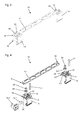
- the in the FIGS. 3 and 4 shown functional unit 10 essentially comprises a spacer bridge 13 and two holders 14, which can be inserted into the groove 12 of the running rail 3.
- the holder 14 and the spacer bridge may also be integrally formed.
- the identical holders 14 can be supplemented and are provided in a first function, to allow the arrangement of a cover 15, which covers the L-shaped running rail 3 from the web 11 to the wing 2, so that the roller carriage 4 and the retraction and damping device 9 are concealed, reducing the sliding door assembly 1 is advantageously visually appealing.
- the first holder 14 may be provided with a buffer 16, which forms a stop for the roller carriage 4 and thus for the wing 2.
- the buffer 16 is in this case assigned to the end 14 arranged on the guide rail 3 holder.
- the second holder 14 is provided with a pin 17 which cooperates as a stationary driver with the intake and damping device 9.
- the pin 17 may be rectangular in cross-section, for example, but also round or oval.
- a number of holders 14 are arranged, which serve to hold the cover 15.
- a further retraction and damping device 9 may be provided, which is provided together with another functional unit 10 for a collection and damping in the open position of the wing 2.
- the holder 14 is shown without the buffer 16 in order to show the arrangement of the wing 2 on the roller carriage 4 and in the running rail 3 unobstructed.
- the distance between the first and the second holder 14 is tuned by the length of the spacer bridge 13 to the retraction and damping device 9, so that the retraction and damping device 9 after engagement with the pin 17 by utilizing the available Effective length of the wing 2 leads to the desired end position, in which the wing 2 is in contact with the buffer 16. Due to the free positioning of the functional unit 10 along the guide rail 3, the desired end position of the wing 2 can be selected without this having an influence on the retraction and damping device 9, since the first holder 14 with the buffer 16 and the second holder 14th are tuned with the pin 17 as a driver through the spacer bridge 13 to the retraction and damping device 9. By choosing different distance bridges 13, the functional unit 10 is on different intake and damping devices 9, which for example for different sash weights and dimensions have a correspondingly different damping travel, adaptable.
- the functional unit 10 is shown in an exploded view, so that all parts are shown.
- associated latching webs 18 are provided, which engage in receptacles 19 of the holder 14 and engage with the receptacles 19 arranged latching lugs 20 so that the holder 14 with the spacer bridge 13 form a unit.
- recesses 21 are provided on the holder, in which the pin 17 can be used, wherein in the recesses 21 in the direction of the pin 17 directed lugs 26 may be provided, which clamped on the pin 17th act.
- the buffer 16 is formed from a carrier 16.1 and a damping insert, for example an elastomer 16.2.
- a damping insert for example an elastomer 16.2.
- the holder 14 has between the receptacles 19 a recess 22 for the arrangement of a nut 23, in which a threaded pin 24 can be screwed.
- the holder 14 can be set in the groove 12 of the running rail 3 by the threaded pin 24 is screwed against the web 11 and so the holder 14 is clamped in the groove 12.
- Fig. 7 shows the holder 14 as a single part in the oblique view, wherein the recess 22 is shown for the nut 23.
- Fig. 5 the side view of the first holder 14 provided with the buffer 16 is shown.
- the buffer 16 is received with its carrier 16.1 in webs 25, supported on the inside of the holder 14 and secured with the pin 17 received in the recesses 21.
- Fig. 6 shows the second holder 14 in the side view, which is provided with the pin 17 as a driver for the retraction and damping device 9.
- On the holder 14 are still several different formed shaped extensions 27, which are provided for the arrangement of depending on the installation situation, such as wall mounting, ceiling mounting or concealed mounting, different covers 15.
- spring webs 28 and sliding webs 29 are arranged, which advantageously a slight displacement and good guidance in the groove 12, in particular the functional unit 10 with two arranged holders 14 effect.
Landscapes
- Engineering & Computer Science (AREA)
- Mechanical Engineering (AREA)
- Support Devices For Sliding Doors (AREA)
Applications Claiming Priority (1)
| Application Number | Priority Date | Filing Date | Title |
|---|---|---|---|
| DE102012203726A DE102012203726B3 (de) | 2012-03-09 | 2012-03-09 | Schiebetüranordnung |
Publications (2)
| Publication Number | Publication Date |
|---|---|
| EP2636836A2 true EP2636836A2 (fr) | 2013-09-11 |
| EP2636836A3 EP2636836A3 (fr) | 2017-05-10 |
Family
ID=47844158
Family Applications (1)
| Application Number | Title | Priority Date | Filing Date |
|---|---|---|---|
| EP13158279.3A Withdrawn EP2636836A3 (fr) | 2012-03-09 | 2013-03-08 | Agencement de porte coulissante |
Country Status (2)
| Country | Link |
|---|---|
| EP (1) | EP2636836A3 (fr) |
| DE (1) | DE102012203726B3 (fr) |
Cited By (2)
| Publication number | Priority date | Publication date | Assignee | Title |
|---|---|---|---|---|
| US9388622B1 (en) | 2015-02-05 | 2016-07-12 | K.N. Crowder Mfg. Inc. | Apparatus for controlling the motion of a sliding door |
| EP3059372B1 (fr) | 2014-01-30 | 2017-10-04 | Gebr. Willach GmbH | Installation de porte coulissante téléscopique |
Families Citing this family (1)
| Publication number | Priority date | Publication date | Assignee | Title |
|---|---|---|---|---|
| EP3020903B1 (fr) * | 2014-11-14 | 2021-11-10 | dormakaba Deutschland GmbH | Support de capot |
Citations (1)
| Publication number | Priority date | Publication date | Assignee | Title |
|---|---|---|---|---|
| DE102009005441A1 (de) | 2008-06-14 | 2009-12-17 | Gebr. Willach Gmbh | Schiebetür |
Family Cites Families (2)
| Publication number | Priority date | Publication date | Assignee | Title |
|---|---|---|---|---|
| DE29807556U1 (de) * | 1998-04-30 | 1999-06-02 | Automatik-Tür-Systeme GmbH, 33378 Rheda-Wiedenbrück | Schiebetüranlage |
| DE202007014567U1 (de) * | 2007-10-16 | 2007-12-13 | Häfele GmbH & Co. KG | Dämpfungs- und Einziehvorrichtung |
-
2012
- 2012-03-09 DE DE102012203726A patent/DE102012203726B3/de active Active
-
2013
- 2013-03-08 EP EP13158279.3A patent/EP2636836A3/fr not_active Withdrawn
Patent Citations (1)
| Publication number | Priority date | Publication date | Assignee | Title |
|---|---|---|---|---|
| DE102009005441A1 (de) | 2008-06-14 | 2009-12-17 | Gebr. Willach Gmbh | Schiebetür |
Cited By (3)
| Publication number | Priority date | Publication date | Assignee | Title |
|---|---|---|---|---|
| EP3059372B1 (fr) | 2014-01-30 | 2017-10-04 | Gebr. Willach GmbH | Installation de porte coulissante téléscopique |
| EP3059372B2 (fr) † | 2014-01-30 | 2025-07-02 | Gebr. Willach GmbH | Installation de porte coulissante telescopique |
| US9388622B1 (en) | 2015-02-05 | 2016-07-12 | K.N. Crowder Mfg. Inc. | Apparatus for controlling the motion of a sliding door |
Also Published As
| Publication number | Publication date |
|---|---|
| DE102012203726B3 (de) | 2013-06-06 |
| EP2636836A3 (fr) | 2017-05-10 |
Similar Documents
| Publication | Publication Date | Title |
|---|---|---|
| DE102009005441B4 (de) | Schiebetür | |
| EP2376734B1 (fr) | Porte coulissante | |
| EP2376732B1 (fr) | Ferrure pour porte coulissante à deux battants | |
| DE102013104420A1 (de) | Führungsanordnung einer Schiebetür, Schiebetür und Möbel | |
| DE102012203726B3 (de) | Schiebetüranordnung | |
| EP2405095B1 (fr) | Joint de porte doté d'un élément de fixation | |
| EP3859105B1 (fr) | Dispositif de fermeture | |
| DE9011081U1 (de) | Schiebetürbeschlag mit einer Feststellpuffereinrichtung | |
| EP3094803B1 (fr) | Système de porte coulissante à vantaux coulissants disposés dans un plan commun | |
| DE102005002759A1 (de) | Schlittenbaugruppe für einen Fensterheber, insbesondere für Fahrzeuge | |
| DE102004062167B4 (de) | Fensterheberanordnung | |
| EP2189558A1 (fr) | Bras de support et de chargement de cylindre supérieur pour un banc d'étirage | |
| EP1951977B1 (fr) | Bloc-porte mécanique pour portes, notamment pour portières de véhicule | |
| DE102008036151A1 (de) | Scharnierband mit einer Unterkonstruktion zur Befestigung an einem Türblatt | |
| DE102014208292B4 (de) | Justierbarer Fensterheber | |
| EP3471982B1 (fr) | Montage en trois points d'une porte coulissante | |
| DE102012210590A1 (de) | Antrieb zum Öffnen und/oder Schließen eines beweglichen Flügels einer Tür oder eines Fensters | |
| DE202015106724U1 (de) | Beschlaganordnung für einen Schiebeflügel | |
| DE102018202813C5 (de) | Mechanischer Auslöser | |
| EP3330465B1 (fr) | Dispositif à charnière limitant l'ouverture | |
| EP1544403B1 (fr) | Vantail, en particulier d'une fenêtre, porte ou paroi | |
| DE102012222200B4 (de) | Bewegungsbegrenzer für einen Flügel einer Schiebetür | |
| EP3854974B1 (fr) | Système de porte coulissante de cabine de douche | |
| AT525275B1 (de) | Führungssystem zur Führung wenigstens eines bewegbaren Möbelteiles | |
| DE102009050417A1 (de) | Schiebetürboxsystem |
Legal Events
| Date | Code | Title | Description |
|---|---|---|---|
| PUAI | Public reference made under article 153(3) epc to a published international application that has entered the european phase |
Free format text: ORIGINAL CODE: 0009012 |
|
| AK | Designated contracting states |
Kind code of ref document: A2 Designated state(s): AL AT BE BG CH CY CZ DE DK EE ES FI FR GB GR HR HU IE IS IT LI LT LU LV MC MK MT NL NO PL PT RO RS SE SI SK SM TR |
|
| AX | Request for extension of the european patent |
Extension state: BA ME |
|
| PUAL | Search report despatched |
Free format text: ORIGINAL CODE: 0009013 |
|
| AK | Designated contracting states |
Kind code of ref document: A3 Designated state(s): AL AT BE BG CH CY CZ DE DK EE ES FI FR GB GR HR HU IE IS IT LI LT LU LV MC MK MT NL NO PL PT RO RS SE SI SK SM TR |
|
| AX | Request for extension of the european patent |
Extension state: BA ME |
|
| RIC1 | Information provided on ipc code assigned before grant |
Ipc: E05D 15/06 20060101ALI20170403BHEP Ipc: E05F 1/16 20060101AFI20170403BHEP |
|
| 17P | Request for examination filed |
Effective date: 20171109 |
|
| RBV | Designated contracting states (corrected) |
Designated state(s): AL AT BE BG CH CY CZ DE DK EE ES FI FR GB GR HR HU IE IS IT LI LT LU LV MC MK MT NL NO PL PT RO RS SE SI SK SM TR |
|
| GRAP | Despatch of communication of intention to grant a patent |
Free format text: ORIGINAL CODE: EPIDOSNIGR1 |
|
| STAA | Information on the status of an ep patent application or granted ep patent |
Free format text: STATUS: THE APPLICATION HAS BEEN WITHDRAWN |
|
| INTG | Intention to grant announced |
Effective date: 20180404 |
|
| 18W | Application withdrawn |
Effective date: 20180419 |