EP3854974B1 - Système de porte coulissante de cabine de douche - Google Patents
Système de porte coulissante de cabine de douche Download PDFInfo
- Publication number
- EP3854974B1 EP3854974B1 EP20152871.8A EP20152871A EP3854974B1 EP 3854974 B1 EP3854974 B1 EP 3854974B1 EP 20152871 A EP20152871 A EP 20152871A EP 3854974 B1 EP3854974 B1 EP 3854974B1
- Authority
- EP
- European Patent Office
- Prior art keywords
- sliding door
- shower cubicle
- driver
- cubicle sliding
- release position
- Prior art date
- Legal status (The legal status is an assumption and is not a legal conclusion. Google has not performed a legal analysis and makes no representation as to the accuracy of the status listed.)
- Active
Links
Images


Classifications
-
- E—FIXED CONSTRUCTIONS
- E05—LOCKS; KEYS; WINDOW OR DOOR FITTINGS; SAFES
- E05F—DEVICES FOR MOVING WINGS INTO OPEN OR CLOSED POSITION; CHECKS FOR WINGS; WING FITTINGS NOT OTHERWISE PROVIDED FOR, CONCERNED WITH THE FUNCTIONING OF THE WING
- E05F5/00—Braking devices, e.g. checks; Stops; Buffers
- E05F5/003—Braking devices, e.g. checks; Stops; Buffers for sliding wings
-
- A—HUMAN NECESSITIES
- A47—FURNITURE; DOMESTIC ARTICLES OR APPLIANCES; COFFEE MILLS; SPICE MILLS; SUCTION CLEANERS IN GENERAL
- A47K—SANITARY EQUIPMENT; ACCESSORIES THEREFOR, e.g. TOILET ACCESSORIES
- A47K3/00—Baths; Showers; Appurtenances therefor
- A47K3/28—Showers or bathing douches
- A47K3/30—Screens or collapsible cabinets for showers or baths
- A47K3/34—Slidable screens
-
- E—FIXED CONSTRUCTIONS
- E05—LOCKS; KEYS; WINDOW OR DOOR FITTINGS; SAFES
- E05D—HINGES OR SUSPENSION DEVICES FOR DOORS, WINDOWS OR WINGS
- E05D15/00—Suspension arrangements for wings
- E05D15/06—Suspension arrangements for wings for wings sliding horizontally more or less in their own plane
- E05D15/0621—Details, e.g. suspension or supporting guides
- E05D15/0626—Details, e.g. suspension or supporting guides for wings suspended at the top
- E05D15/063—Details, e.g. suspension or supporting guides for wings suspended at the top on wheels with fixed axis
-
- E—FIXED CONSTRUCTIONS
- E05—LOCKS; KEYS; WINDOW OR DOOR FITTINGS; SAFES
- E05D—HINGES OR SUSPENSION DEVICES FOR DOORS, WINDOWS OR WINGS
- E05D5/00—Construction of single parts, e.g. the parts for attachment
- E05D5/02—Parts for attachment, e.g. flaps
- E05D5/0246—Parts for attachment, e.g. flaps for attachment to glass panels
-
- E—FIXED CONSTRUCTIONS
- E05—LOCKS; KEYS; WINDOW OR DOOR FITTINGS; SAFES
- E05F—DEVICES FOR MOVING WINGS INTO OPEN OR CLOSED POSITION; CHECKS FOR WINGS; WING FITTINGS NOT OTHERWISE PROVIDED FOR, CONCERNED WITH THE FUNCTIONING OF THE WING
- E05F1/00—Closers or openers for wings, not otherwise provided for in this subclass
- E05F1/08—Closers or openers for wings, not otherwise provided for in this subclass spring-actuated, e.g. for horizontally sliding wings
- E05F1/16—Closers or openers for wings, not otherwise provided for in this subclass spring-actuated, e.g. for horizontally sliding wings for sliding wings
-
- E—FIXED CONSTRUCTIONS
- E05—LOCKS; KEYS; WINDOW OR DOOR FITTINGS; SAFES
- E05Y—INDEXING SCHEME ASSOCIATED WITH SUBCLASSES E05D AND E05F, RELATING TO CONSTRUCTION ELEMENTS, ELECTRIC CONTROL, POWER SUPPLY, POWER SIGNAL OR TRANSMISSION, USER INTERFACES, MOUNTING OR COUPLING, DETAILS, ACCESSORIES, AUXILIARY OPERATIONS NOT OTHERWISE PROVIDED FOR, APPLICATION THEREOF
- E05Y2201/00—Constructional elements; Accessories therefor
- E05Y2201/40—Motors; Magnets; Springs; Weights; Accessories therefor
- E05Y2201/404—Function thereof
- E05Y2201/41—Function thereof for closing
- E05Y2201/412—Function thereof for closing for the final closing movement
-
- E—FIXED CONSTRUCTIONS
- E05—LOCKS; KEYS; WINDOW OR DOOR FITTINGS; SAFES
- E05Y—INDEXING SCHEME ASSOCIATED WITH SUBCLASSES E05D AND E05F, RELATING TO CONSTRUCTION ELEMENTS, ELECTRIC CONTROL, POWER SUPPLY, POWER SIGNAL OR TRANSMISSION, USER INTERFACES, MOUNTING OR COUPLING, DETAILS, ACCESSORIES, AUXILIARY OPERATIONS NOT OTHERWISE PROVIDED FOR, APPLICATION THEREOF
- E05Y2201/00—Constructional elements; Accessories therefor
- E05Y2201/40—Motors; Magnets; Springs; Weights; Accessories therefor
- E05Y2201/404—Function thereof
- E05Y2201/422—Function thereof for opening
- E05Y2201/424—Function thereof for opening for the final opening movement
-
- E—FIXED CONSTRUCTIONS
- E05—LOCKS; KEYS; WINDOW OR DOOR FITTINGS; SAFES
- E05Y—INDEXING SCHEME ASSOCIATED WITH SUBCLASSES E05D AND E05F, RELATING TO CONSTRUCTION ELEMENTS, ELECTRIC CONTROL, POWER SUPPLY, POWER SIGNAL OR TRANSMISSION, USER INTERFACES, MOUNTING OR COUPLING, DETAILS, ACCESSORIES, AUXILIARY OPERATIONS NOT OTHERWISE PROVIDED FOR, APPLICATION THEREOF
- E05Y2201/00—Constructional elements; Accessories therefor
- E05Y2201/60—Suspension or transmission members; Accessories therefor
- E05Y2201/622—Suspension or transmission members elements
- E05Y2201/64—Carriers
-
- E—FIXED CONSTRUCTIONS
- E05—LOCKS; KEYS; WINDOW OR DOOR FITTINGS; SAFES
- E05Y—INDEXING SCHEME ASSOCIATED WITH SUBCLASSES E05D AND E05F, RELATING TO CONSTRUCTION ELEMENTS, ELECTRIC CONTROL, POWER SUPPLY, POWER SIGNAL OR TRANSMISSION, USER INTERFACES, MOUNTING OR COUPLING, DETAILS, ACCESSORIES, AUXILIARY OPERATIONS NOT OTHERWISE PROVIDED FOR, APPLICATION THEREOF
- E05Y2800/00—Details, accessories and auxiliary operations not otherwise provided for
- E05Y2800/20—Combinations of elements
- E05Y2800/23—Combinations of elements of elements of different categories
- E05Y2800/24—Combinations of elements of elements of different categories of springs and brakes
-
- E—FIXED CONSTRUCTIONS
- E05—LOCKS; KEYS; WINDOW OR DOOR FITTINGS; SAFES
- E05Y—INDEXING SCHEME ASSOCIATED WITH SUBCLASSES E05D AND E05F, RELATING TO CONSTRUCTION ELEMENTS, ELECTRIC CONTROL, POWER SUPPLY, POWER SIGNAL OR TRANSMISSION, USER INTERFACES, MOUNTING OR COUPLING, DETAILS, ACCESSORIES, AUXILIARY OPERATIONS NOT OTHERWISE PROVIDED FOR, APPLICATION THEREOF
- E05Y2900/00—Application of doors, windows, wings or fittings thereof
- E05Y2900/10—Application of doors, windows, wings or fittings thereof for buildings or parts thereof
- E05Y2900/114—Application of doors, windows, wings or fittings thereof for buildings or parts thereof for showers
Definitions
- the invention relates to a shower cubicle comprising a shower cubicle sliding door system according to the invention.
- the sliding doors are usually slidably mounted on rollers on a frame structure.
- the end positions of the sliding doors are limited by stops, it being possible for the reaching of the end positions to be dampened, for example, by the contact of sealing lips.
- the respective sliding door of the system When approaching the end position, the respective sliding door of the system is guided to the end position automatically and in a controlled manner.
- the second engagement portion is formed as a projection and the first engagement portion is formed as a depression corresponding thereto.
- the carrying body consists of chrome-plated brass.
- each clamp in turn consists of a metal outer shell and a plastic carrier body accommodated within the metal outer shell.
- the shower cubicle sliding door system has a damped closing device which is firmly connected to the frame construction and is arranged on the frame construction in such a way that the shower cubicle sliding door can be closed in a damped manner.
- the shower cubicle sliding door system has a damped closing device which is firmly connected to the frame construction and is arranged on the frame construction in such a way that the shower cubicle sliding door can reach a maximum opening position in a damped manner.
- the shower cubicle sliding door is flat.
- the invention further relates to a shower cubicle comprising a shower cubicle sliding door system according to the invention.
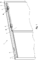
- FIG 1 shows a schematic representation of a shower cubicle sliding door system 1 according to the invention.
- the shower cubicle sliding door system 1 comprises a frame construction 2 for the suspension and guidance of at least one shower cubicle sliding door 3, at least one shower cubicle sliding door 3, and at least two guide devices 4, which are fixed at a distance from one another at an upper end of the shower cubicle sliding door 3, wherein each guide device 4 has at least one rotatably mounted roller 4b.
- the frame construction 2 has at least one guide channel 2a for guiding the rollers 4b, and the rollers 4b are set up to engage in this guide channel 2a and thereby allow the shower cubicle sliding door 3 to be displaced in relation to the frame construction 2.
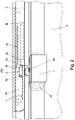
- the shower cubicle sliding door system 1 also comprises at least one damped closing device 5 firmly connected to the frame structure 2, the damped closing device 5 having a driver 5a with a first engagement section 5a' and a clamping means 5a" and a damping device 5b with a rod 5b' which is mounted in a damped manner so that it can be displaced along a displacement axis x.
- the driver 5a is connected to the rod 5b' and can be displaced together with the rod 5b'.
- the damped closing device has a clamping device 5c, the displaceability of the driver 5a along the displacement axis x between a release position P1 (see 3 ) and an end position P2 (see also figure 1 and 2 ) is limited, wherein between the release position P1 and the end position P2 a damping working area is formed by the damping device 5b, which extends to the end position P2.
- the clamping means 5c is set up to exert a force on the driver 5a, this force in the direction of the end position P2 opposite to the direction of the arrow in FIG 3 works.
- the end position P2 can be limited, for example, by a mechanical stop, which can be formed, for example, in the damper 5b.
- the driver 5a is mounted so that it can pivot in relation to the rod 5b' in order to switch between a driving position L2 (see 2 ) and a release position L1 (see 3 ) to be pivoted, wherein the locking device 5 also has a guide slot 5d, with the driver 5a is guided to change between driving position L2 and release position L1.
- the guide link 5d is designed in such a way that the driver 5a is rotated in relation to the rod 5b' when transferring to the release position P1, starting from the driver position L2 and into the release position L1, with the clamping means 5a" of the driver 5a being in the release position L1 with the locking device 5 is engaged in such a way that the driver 5a is held clamped against the force of the clamping device 5c on the locking device 5.
- the clamping device 5a" is guided in the guide slot 5d - for example in the form of a pin which is guided in a groove is, through which the guide slot 5d is formed.
- a second engagement section 4a' is provided on at least one of the at least two guide devices 4 for mechanical engagement in the first engagement section 5a', with the mechanical coupling of the two engagement sections 4a', 5a' being set up such that, starting from a position in which the driver 5a is in the release position L1, when approaching (against the direction of the arrow according to 3 ) of the second engagement portion 4a 'towards the driver 5a of the driver 5a by engaging in the second engagement section 4a' is pivoted into the driving position L2, in which the clamping means 5a" is released from a clamping position and the shower cubicle sliding door 3 can be moved to the end position P2 by means of the driver 5a due to the force of the clamping means 5c against the damping force of the damping device.
- the mechanical coupling of the two engagement sections 4a', 5a' is also set up so that, starting from a position in which the driver is in the driving position L2 and the two engagement sections 4a', 5a' engage in one another, the shower cubicle sliding door 3 together with the Driver 5a can be displaced counter to the force of the clamping means 5c towards the release position P1, with the driver 5a being guided back into the release position L1 when it reaches the release position P1 by being guided in the guide slot 5d, with a further displacement movement pointing away from the end position P2 in the release position L1 release the shower cubicle sliding door 3 and thus the position of the driver 5a is decoupled from the position of the second engagement section 4a'.
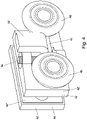
- each guide device 4 can also be made for each guide device 4 to have two rollers 4b and a metal support body 4c, with the rollers 4b being rotatably mounted on the support body 4c and the second engagement section 5a′ in the form of the projection protruding from the support body 4c.
- each guide device 4 has two clamps 4d that can be connected to one another, with a section of the shower cubicle sliding door 3 being framed by these clamps 4d, with a shaft 4e, which is oriented vertically in the assembled state, being formed on one of the two clamps 4d in each case.
- the supporting body 4c being fastened to the shaft 4e and being pivotable together with the rollers 4b in relation to the brackets 4d.
- the shaft 4e is formed by a threaded portion of a screw held in the supporting body 4c.
- Each clamp 4d in turn consists of a metal outer shell 4d' and a plastic carrier body 4d'' accommodated within the metal outer shell 4d'.
- the shower cubicle sliding door system 1 has a damped closing device 5 which is firmly connected to the frame construction 2 and which is arranged on the frame construction 2 in such a way that the shower cubicle sliding door 3 can be closed in a damped manner.
- the shower cubicle sliding door system 1 has a damped closing device 5 which is firmly connected to the frame construction 2 and which is arranged on the frame construction 2 in such a way that the shower cubicle sliding door 3 can reach a maximum opening position in a damped manner.
Landscapes
- Engineering & Computer Science (AREA)
- Mechanical Engineering (AREA)
- Health & Medical Sciences (AREA)
- Public Health (AREA)
- Epidemiology (AREA)
- General Health & Medical Sciences (AREA)
- Residential Or Office Buildings (AREA)
- Support Devices For Sliding Doors (AREA)
Claims (8)
- Système de porte coulissante de cabine de douche (1) comprenant- une structure de cadre (2) pour suspendre et guider au moins une porte coulissante de cabine de douche (3),- au moins une porte coulissante de cabine de douche (3), et- au moins deux dispositifs de guidage (4) qui sont fixés à une extrémité supérieure de la porte coulissante de cabine de douche (3) à une certaine distance l'un de l'autre, chaque dispositif de guidage (4) présentant au moins un galet (4b) logé de manière rotative,la construction de cadre (2) présentant au moins un canal de guidage (2a) pour guider les galets (4b), et les galets (4b) étant adaptés pour s'engager dans ce canal de guidage (2a) et permettre ainsi un déplacement de la porte coulissante de cabine de douche (3) par rapport à la construction de cadre (2),dans lequel
le système de porte coulissante de cabine de douche (1) comprend en outre- comprend au moins un dispositif de fermeture amorti (5) solidaire de la structure de cadre (2), ledit dispositif de fermeture amorti (5)- un entraîneur (5a) avec∘ une première section d'engagement (5a') et∘ un moyen de serrage (5a"),- un dispositif d'amortissement (5b) avec un axe de déplacement (x)une tige (5b') montée de manière à pouvoir coulisser de façon amortie, l'entraîneur (5a) étant relié à la tige (5b') et pouvant coulisser avec la tige (5b'), et- un moyen de serrage (5c),la capacité de déplacement de l'entraîneur (Sa) le long de l'axe de déplacement (x) étant limitée entre une position de libération (P1) et une position de fin de course (P2), une zone de travail d'amortissement étant formée entre la position de libération (P1) et la position de fin de course (P2) par le dispositif d'amortissement (5b), laquelle s'étend jusqu'à la position de fin de course, le moyen de serrage (5c) étant conçu pour exercer une force sur l'entraîneur (Sa), dans lequel cette force agit en direction de la position finale (P2),
oùl'entraîneur (5a) est monté pivotant par rapport à la tige (5b') pour être pivoté entre une position d'entraînement (L2) et une position de libération (L1), le dispositif de fermeture (5) présentant en outre une coulisse de guidage (5d) avec laquelle l'entraîneur (5a) est guidé pour le changement entre la position d'entraînement (L2) et la position de libération (L1), la coulisse de guidage (5d) étant réalisée de telle sorte, que l'entraîneur (5a), lors du transfert dans la position de libération (P1), est tourné par rapport à la tige (5b') en partant de la position d'entraînement (L2) vers la position de libération (L1), le moyen de serrage (Sa") de l'entraîneur (5a) étant en prise avec le dispositif de fermeture (5) dans la position de libération (L1) de telle sorte que l'entraîneur (5a) est maintenu par serrage contre la force du moyen de serrage (5c) sur le dispositif de fermeture (5),une deuxième section d'engrènement (4a') conçue pour l'engrènement mécanique dans la première section d'engrènement (5a') étant prévue sur au moins l'un des au moins deux dispositifs de guidage (4), le couplage mécanique des deux sections d'engrènement (4a', Sa') étant conçu de telle sorte qu'en partant d'une position dans laquelle l'entraîneur (Sa) se trouve dans la position de libération (L1), lorsque la deuxième section d'engagement (4a') est approchée de l'entraîneur (5a), l'entraîneur (5a) est pivoté dans la position d'entraînement (L2) par engagement avec la deuxième section d'engagement (4a'), dans laquelle le moyen de serrage (5a") peut être libéré d'une position de serrage et la porte coulissante de cabine de douche (3) peut être transférée dans la position finale (P2) au moyen de l'entraîneur (5a) en raison de l'effet de force du moyen de serrage (5c) à l'encontre de la force d'amortissement du dispositif d'amortissement, et l'accouplement mécanique des deux sections d'engagement (4a', Sa') étant en outre conçu pour qu'en partant d'une position dans laquelle l'entraîneur se trouve dans la position d'entraînement (L2) et les deux sections d'engagement (4a', 5a') s'engagent l'une dans l'autre, la porte coulissante de cabine de douche (3) peut être déplacée avec l'entraîneur (Sa) à l'encontre de l'effet de force du moyen de serrage (5c) vers la position de libération (P1), l'entraîneur (5a) étant ramené dans la position de libération (L1) par guidage dans la coulisse de guidage (5d) lorsque la position de libération (P1) est atteinte, un autre mouvement de coulissement de la porte coulissante de cabine de douche (3) s'éloignant de la position finale (P2) étant libéré dans la position de libération (L1) et la position de l'entraîneur (5a) étant ainsi découplée de la position de la deuxième section d'engagement (4a'), chaque dispositif de guidage (4) comprenant deux galets (4b) et un corps de support métallique (4c), les galets (4b) étant montés rotatifs sur le corps de support (4c) et la deuxième section d'engagement (5a') étant en forme de saillie du corps de support (4c), chaque dispositif de guidage (4) présentant deux colliers (4d) pouvant être reliés l'un à l'autre, un tronçon de la porte coulissante de cabine de douche (3) est entourée par ces colliers (4d),caractérisé en ce que un arbre (4e) orienté verticalement à l'état monté est monté sur l'un des deux colliers (4d). le corps de support (4c) étant fixé à l'arbre (4e) et pouvant pivoter avec les galets (4b) par rapport aux colliers (4d), l'arbre (4e) étant formé par une partie filetée d'une vis qui est maintenue dans le corps de support (4c). - Système de porte coulissante de cabine de douche (1) selon la revendication 1, dans lequel la deuxième section d'engagement (4a') est réalisée sous forme de saillie et la première section d'engagement (5a') est réalisée sous forme de creux correspondant à celle-ci.
- Système de porte coulissante de cabine de douche (1) selon la revendication 1 ou 2, dans lequel le corps de support (4c) est en laiton chromé.
- Système de porte coulissante de cabine de douche (1) selon l'une quelconque des revendications précédentes, dans lequel chaque attache est réalisée en acier inoxydable. collier (4d) est à son tour constitué d'une coque métallique extérieure (4d') et de (4d') et d'un corps de support en plastique (4d").
- Système de porte coulissante de cabine de douche (1) selon l'une quelconque des revendications précédentes, dans lequel le système de porte coulissante de cabine de douche Système de porte coulissante de cabine de douche (1) comprenant un dispositif de fermeture amorti (5) solidaire de la structure de cadre (2) et disposé sur la structure de cadre (2) de telle sorte qu'il permette de provoquer une fermeture amortie de la porte coulissante de cabine de douche (3).
- Système de porte coulissante de cabine de douche (1) selon l'une quelconque des revendications précédentes, dans lequel le système de porte coulissante de cabine de douche (1) est conçu de manière à ce que la porte coulissante de cabine de douche (1) ne soit pas ouverte. Système de porte coulissante de cabine de douche (1) présente un dispositif de fermeture amorti (5) solidaire de la structure de cadre (2), qui est disposé sur la structure de cadre (2) de telle sorte que l'atteinte d'une position d'ouverture maximale de la porte coulissante de cabine de douche (3) peut ainsi être provoquée de manière amortie.
- Système de porte coulissante de cabine de douche (1) selon l'une quelconque des revendications précédentes, dans lequel la porte coulissante de cabine de douche (3) est plane.
- Cabine de douche comprenant un système de porte coulissante de cabine de douche (1) selon l'une des revendications précédentes revendications précédentes.
Priority Applications (1)
| Application Number | Priority Date | Filing Date | Title |
|---|---|---|---|
| EP20152871.8A EP3854974B1 (fr) | 2020-01-21 | 2020-01-21 | Système de porte coulissante de cabine de douche |
Applications Claiming Priority (1)
| Application Number | Priority Date | Filing Date | Title |
|---|---|---|---|
| EP20152871.8A EP3854974B1 (fr) | 2020-01-21 | 2020-01-21 | Système de porte coulissante de cabine de douche |
Publications (2)
| Publication Number | Publication Date |
|---|---|
| EP3854974A1 EP3854974A1 (fr) | 2021-07-28 |
| EP3854974B1 true EP3854974B1 (fr) | 2022-09-07 |
Family
ID=69185505
Family Applications (1)
| Application Number | Title | Priority Date | Filing Date |
|---|---|---|---|
| EP20152871.8A Active EP3854974B1 (fr) | 2020-01-21 | 2020-01-21 | Système de porte coulissante de cabine de douche |
Country Status (1)
| Country | Link |
|---|---|
| EP (1) | EP3854974B1 (fr) |
Citations (7)
| Publication number | Priority date | Publication date | Assignee | Title |
|---|---|---|---|---|
| EP0956799A2 (fr) | 1998-05-13 | 1999-11-17 | DORMA GmbH + Co. KG | Cloison pour douches |
| DE19914319A1 (de) | 1999-03-29 | 2000-10-12 | Dorma Gmbh & Co Kg | Duschabtrennung |
| DE202013100200U1 (de) | 2013-01-15 | 2013-01-25 | Ideal Sanitary Ware Co., Ltd. | Eine Duschtür mit verborgenen Puffervorrichtungen |
| EP2617336A2 (fr) | 2012-01-20 | 2013-07-24 | Schulte Duschkabinenbau GmbH & Co. KG | Séparation de douche |
| DE202013007992U1 (de) | 2013-07-30 | 2013-10-15 | Foshan Ideal Co., Ltd | Duschtür-Baugruppe mit selbstschließender Funktion |
| US20150033502A1 (en) | 2013-07-30 | 2015-02-05 | Ideal Sanitary Ware Co., Ltd. | Pulley mechanism |
| GB2535441A (en) | 2015-01-08 | 2016-08-24 | Lorenzo Darren | Adjustable runner apparatus |
-
2020
- 2020-01-21 EP EP20152871.8A patent/EP3854974B1/fr active Active
Patent Citations (7)
| Publication number | Priority date | Publication date | Assignee | Title |
|---|---|---|---|---|
| EP0956799A2 (fr) | 1998-05-13 | 1999-11-17 | DORMA GmbH + Co. KG | Cloison pour douches |
| DE19914319A1 (de) | 1999-03-29 | 2000-10-12 | Dorma Gmbh & Co Kg | Duschabtrennung |
| EP2617336A2 (fr) | 2012-01-20 | 2013-07-24 | Schulte Duschkabinenbau GmbH & Co. KG | Séparation de douche |
| DE202013100200U1 (de) | 2013-01-15 | 2013-01-25 | Ideal Sanitary Ware Co., Ltd. | Eine Duschtür mit verborgenen Puffervorrichtungen |
| DE202013007992U1 (de) | 2013-07-30 | 2013-10-15 | Foshan Ideal Co., Ltd | Duschtür-Baugruppe mit selbstschließender Funktion |
| US20150033502A1 (en) | 2013-07-30 | 2015-02-05 | Ideal Sanitary Ware Co., Ltd. | Pulley mechanism |
| GB2535441A (en) | 2015-01-08 | 2016-08-24 | Lorenzo Darren | Adjustable runner apparatus |
Also Published As
| Publication number | Publication date |
|---|---|
| EP3854974A1 (fr) | 2021-07-28 |
Similar Documents
| Publication | Publication Date | Title |
|---|---|---|
| DE69001041T2 (de) | Moebelscharnier, insbesondere mit scharniertopf. | |
| DE102017113862B3 (de) | Endlagedämpfungsvorrichtung und Anordnung mit einer Endlagedämpfungsvorrichtung | |
| DE102008022096A1 (de) | Stangeneinstellklemme für Fahrzeugtür | |
| EP3625415B1 (fr) | Palier de volet équipé d'un accessoire de réglage | |
| WO2020236100A1 (fr) | Ferrure pour meuble | |
| EP3580418A1 (fr) | Charnière pour meuble facile à monter | |
| EP3050413B1 (fr) | Dispositif de ventilation | |
| EP2180121B1 (fr) | Dispositif de fixation d'un capot en position | |
| EP3511499B1 (fr) | Dispositif de fixation pivotante d'un vantail de porte sur un dormant | |
| DE102013104420A1 (de) | Führungsanordnung einer Schiebetür, Schiebetür und Möbel | |
| EP2672045B1 (fr) | Agencement de guidage d'une porte coulissante d'un meuble à porte coulissante | |
| EP3854974B1 (fr) | Système de porte coulissante de cabine de douche | |
| EP3251571A1 (fr) | Charnière de pivotement pour une porte | |
| DE2530199A1 (de) | Halterung zum befestigen eines geraetes der nachrichtentechnik | |
| DE69402940T2 (de) | Türhalter mit wählbarer Reibungsunterstützung | |
| DE69400735T2 (de) | Vorrichtung zum Anbringen von Dichtungen | |
| DE102005002759A1 (de) | Schlittenbaugruppe für einen Fensterheber, insbesondere für Fahrzeuge | |
| DE4400249C1 (de) | Wandinstallationskanal für Elektroinstallationseinrichtungen | |
| DE102020119523B4 (de) | Verfahren zur Installation eines Garagentors | |
| EP2636836A2 (fr) | Agencement de porte coulissante | |
| DE19700619B4 (de) | Gelenkband mit Schließkraftverstellung | |
| EP0619635B1 (fr) | Pièce de soutien pour plusieurs câbles ou tubes | |
| DE102012104863B3 (de) | Türbandanordnung mit einem Türband und einem Aufnahmeelement | |
| EP3656958B1 (fr) | Entraînement auxiliaire pourvu de dispositif d'amortissement pour un battant de portail motorisée ainsi que portail, dont battant de portail est équipé d'un entraînement auxiliaire contenant un dispositif d'amortissement | |
| DE10161808B4 (de) | Behälter, insbesondere Müllbehälter |
Legal Events
| Date | Code | Title | Description |
|---|---|---|---|
| PUAI | Public reference made under article 153(3) epc to a published international application that has entered the european phase |
Free format text: ORIGINAL CODE: 0009012 |
|
| STAA | Information on the status of an ep patent application or granted ep patent |
Free format text: STATUS: THE APPLICATION HAS BEEN PUBLISHED |
|
| AK | Designated contracting states |
Kind code of ref document: A1 Designated state(s): AL AT BE BG CH CY CZ DE DK EE ES FI FR GB GR HR HU IE IS IT LI LT LU LV MC MK MT NL NO PL PT RO RS SE SI SK SM TR |
|
| STAA | Information on the status of an ep patent application or granted ep patent |
Free format text: STATUS: REQUEST FOR EXAMINATION WAS MADE |
|
| 17P | Request for examination filed |
Effective date: 20220125 |
|
| RBV | Designated contracting states (corrected) |
Designated state(s): AL AT BE BG CH CY CZ DE DK EE ES FI FR GB GR HR HU IE IS IT LI LT LU LV MC MK MT NL NO PL PT RO RS SE SI SK SM TR |
|
| GRAP | Despatch of communication of intention to grant a patent |
Free format text: ORIGINAL CODE: EPIDOSNIGR1 |
|
| STAA | Information on the status of an ep patent application or granted ep patent |
Free format text: STATUS: GRANT OF PATENT IS INTENDED |
|
| INTG | Intention to grant announced |
Effective date: 20220412 |
|
| GRAS | Grant fee paid |
Free format text: ORIGINAL CODE: EPIDOSNIGR3 |
|
| GRAA | (expected) grant |
Free format text: ORIGINAL CODE: 0009210 |
|
| STAA | Information on the status of an ep patent application or granted ep patent |
Free format text: STATUS: THE PATENT HAS BEEN GRANTED |
|
| AK | Designated contracting states |
Kind code of ref document: B1 Designated state(s): AL AT BE BG CH CY CZ DE DK EE ES FI FR GB GR HR HU IE IS IT LI LT LU LV MC MK MT NL NO PL PT RO RS SE SI SK SM TR |
|
| REG | Reference to a national code |
Ref country code: GB Ref legal event code: FG4D Free format text: NOT ENGLISH |
|
| REG | Reference to a national code |
Ref country code: CH Ref legal event code: EP Ref country code: AT Ref legal event code: REF Ref document number: 1517174 Country of ref document: AT Kind code of ref document: T Effective date: 20220915 |
|
| REG | Reference to a national code |
Ref country code: DE Ref legal event code: R096 Ref document number: 502020001627 Country of ref document: DE |
|
| REG | Reference to a national code |
Ref country code: IE Ref legal event code: FG4D Free format text: LANGUAGE OF EP DOCUMENT: GERMAN |
|
| REG | Reference to a national code |
Ref country code: LT Ref legal event code: MG9D |
|
| REG | Reference to a national code |
Ref country code: NL Ref legal event code: MP Effective date: 20220907 |
|
| PG25 | Lapsed in a contracting state [announced via postgrant information from national office to epo] |
Ref country code: SE Free format text: LAPSE BECAUSE OF FAILURE TO SUBMIT A TRANSLATION OF THE DESCRIPTION OR TO PAY THE FEE WITHIN THE PRESCRIBED TIME-LIMIT Effective date: 20220907 Ref country code: RS Free format text: LAPSE BECAUSE OF FAILURE TO SUBMIT A TRANSLATION OF THE DESCRIPTION OR TO PAY THE FEE WITHIN THE PRESCRIBED TIME-LIMIT Effective date: 20220907 Ref country code: NO Free format text: LAPSE BECAUSE OF FAILURE TO SUBMIT A TRANSLATION OF THE DESCRIPTION OR TO PAY THE FEE WITHIN THE PRESCRIBED TIME-LIMIT Effective date: 20221207 Ref country code: LV Free format text: LAPSE BECAUSE OF FAILURE TO SUBMIT A TRANSLATION OF THE DESCRIPTION OR TO PAY THE FEE WITHIN THE PRESCRIBED TIME-LIMIT Effective date: 20220907 Ref country code: LT Free format text: LAPSE BECAUSE OF FAILURE TO SUBMIT A TRANSLATION OF THE DESCRIPTION OR TO PAY THE FEE WITHIN THE PRESCRIBED TIME-LIMIT Effective date: 20220907 Ref country code: FI Free format text: LAPSE BECAUSE OF FAILURE TO SUBMIT A TRANSLATION OF THE DESCRIPTION OR TO PAY THE FEE WITHIN THE PRESCRIBED TIME-LIMIT Effective date: 20220907 |
|
| PG25 | Lapsed in a contracting state [announced via postgrant information from national office to epo] |
Ref country code: HR Free format text: LAPSE BECAUSE OF FAILURE TO SUBMIT A TRANSLATION OF THE DESCRIPTION OR TO PAY THE FEE WITHIN THE PRESCRIBED TIME-LIMIT Effective date: 20220907 Ref country code: GR Free format text: LAPSE BECAUSE OF FAILURE TO SUBMIT A TRANSLATION OF THE DESCRIPTION OR TO PAY THE FEE WITHIN THE PRESCRIBED TIME-LIMIT Effective date: 20221208 |
|
| PG25 | Lapsed in a contracting state [announced via postgrant information from national office to epo] |
Ref country code: SM Free format text: LAPSE BECAUSE OF FAILURE TO SUBMIT A TRANSLATION OF THE DESCRIPTION OR TO PAY THE FEE WITHIN THE PRESCRIBED TIME-LIMIT Effective date: 20220907 Ref country code: RO Free format text: LAPSE BECAUSE OF FAILURE TO SUBMIT A TRANSLATION OF THE DESCRIPTION OR TO PAY THE FEE WITHIN THE PRESCRIBED TIME-LIMIT Effective date: 20220907 Ref country code: PT Free format text: LAPSE BECAUSE OF FAILURE TO SUBMIT A TRANSLATION OF THE DESCRIPTION OR TO PAY THE FEE WITHIN THE PRESCRIBED TIME-LIMIT Effective date: 20230109 Ref country code: ES Free format text: LAPSE BECAUSE OF FAILURE TO SUBMIT A TRANSLATION OF THE DESCRIPTION OR TO PAY THE FEE WITHIN THE PRESCRIBED TIME-LIMIT Effective date: 20220907 Ref country code: CZ Free format text: LAPSE BECAUSE OF FAILURE TO SUBMIT A TRANSLATION OF THE DESCRIPTION OR TO PAY THE FEE WITHIN THE PRESCRIBED TIME-LIMIT Effective date: 20220907 |
|
| PG25 | Lapsed in a contracting state [announced via postgrant information from national office to epo] |
Ref country code: SK Free format text: LAPSE BECAUSE OF FAILURE TO SUBMIT A TRANSLATION OF THE DESCRIPTION OR TO PAY THE FEE WITHIN THE PRESCRIBED TIME-LIMIT Effective date: 20220907 Ref country code: PL Free format text: LAPSE BECAUSE OF FAILURE TO SUBMIT A TRANSLATION OF THE DESCRIPTION OR TO PAY THE FEE WITHIN THE PRESCRIBED TIME-LIMIT Effective date: 20220907 Ref country code: IS Free format text: LAPSE BECAUSE OF FAILURE TO SUBMIT A TRANSLATION OF THE DESCRIPTION OR TO PAY THE FEE WITHIN THE PRESCRIBED TIME-LIMIT Effective date: 20230107 Ref country code: EE Free format text: LAPSE BECAUSE OF FAILURE TO SUBMIT A TRANSLATION OF THE DESCRIPTION OR TO PAY THE FEE WITHIN THE PRESCRIBED TIME-LIMIT Effective date: 20220907 |
|
| REG | Reference to a national code |
Ref country code: DE Ref legal event code: R026 Ref document number: 502020001627 Country of ref document: DE |
|
| PLBI | Opposition filed |
Free format text: ORIGINAL CODE: 0009260 |
|
| P01 | Opt-out of the competence of the unified patent court (upc) registered |
Effective date: 20230524 |
|
| PLAX | Notice of opposition and request to file observation + time limit sent |
Free format text: ORIGINAL CODE: EPIDOSNOBS2 |
|
| PG25 | Lapsed in a contracting state [announced via postgrant information from national office to epo] |
Ref country code: NL Free format text: LAPSE BECAUSE OF FAILURE TO SUBMIT A TRANSLATION OF THE DESCRIPTION OR TO PAY THE FEE WITHIN THE PRESCRIBED TIME-LIMIT Effective date: 20220907 Ref country code: AL Free format text: LAPSE BECAUSE OF FAILURE TO SUBMIT A TRANSLATION OF THE DESCRIPTION OR TO PAY THE FEE WITHIN THE PRESCRIBED TIME-LIMIT Effective date: 20220907 |
|
| 26 | Opposition filed |
Opponent name: SCHULTE DUSCHKABINENBAU GMBH & CO. KG Effective date: 20230607 |
|
| PG25 | Lapsed in a contracting state [announced via postgrant information from national office to epo] |
Ref country code: DK Free format text: LAPSE BECAUSE OF FAILURE TO SUBMIT A TRANSLATION OF THE DESCRIPTION OR TO PAY THE FEE WITHIN THE PRESCRIBED TIME-LIMIT Effective date: 20220907 |
|
| PG25 | Lapsed in a contracting state [announced via postgrant information from national office to epo] |
Ref country code: SI Free format text: LAPSE BECAUSE OF FAILURE TO SUBMIT A TRANSLATION OF THE DESCRIPTION OR TO PAY THE FEE WITHIN THE PRESCRIBED TIME-LIMIT Effective date: 20220907 |
|
| REG | Reference to a national code |
Ref country code: CH Ref legal event code: PL |
|
| PG25 | Lapsed in a contracting state [announced via postgrant information from national office to epo] |
Ref country code: LU Free format text: LAPSE BECAUSE OF NON-PAYMENT OF DUE FEES Effective date: 20230121 |
|
| REG | Reference to a national code |
Ref country code: BE Ref legal event code: MM Effective date: 20230131 |
|
| PG25 | Lapsed in a contracting state [announced via postgrant information from national office to epo] |
Ref country code: LI Free format text: LAPSE BECAUSE OF NON-PAYMENT OF DUE FEES Effective date: 20230131 Ref country code: CH Free format text: LAPSE BECAUSE OF NON-PAYMENT OF DUE FEES Effective date: 20230131 |
|
| PLBB | Reply of patent proprietor to notice(s) of opposition received |
Free format text: ORIGINAL CODE: EPIDOSNOBS3 |
|
| PG25 | Lapsed in a contracting state [announced via postgrant information from national office to epo] |
Ref country code: FR Free format text: LAPSE BECAUSE OF NON-PAYMENT OF DUE FEES Effective date: 20230131 Ref country code: BE Free format text: LAPSE BECAUSE OF NON-PAYMENT OF DUE FEES Effective date: 20230131 |
|
| PG25 | Lapsed in a contracting state [announced via postgrant information from national office to epo] |
Ref country code: IE Free format text: LAPSE BECAUSE OF NON-PAYMENT OF DUE FEES Effective date: 20230121 |
|
| PG25 | Lapsed in a contracting state [announced via postgrant information from national office to epo] |
Ref country code: IT Free format text: LAPSE BECAUSE OF FAILURE TO SUBMIT A TRANSLATION OF THE DESCRIPTION OR TO PAY THE FEE WITHIN THE PRESCRIBED TIME-LIMIT Effective date: 20220907 |
|
| PG25 | Lapsed in a contracting state [announced via postgrant information from national office to epo] |
Ref country code: MC Free format text: LAPSE BECAUSE OF FAILURE TO SUBMIT A TRANSLATION OF THE DESCRIPTION OR TO PAY THE FEE WITHIN THE PRESCRIBED TIME-LIMIT Effective date: 20220907 |
|
| PG25 | Lapsed in a contracting state [announced via postgrant information from national office to epo] |
Ref country code: MC Free format text: LAPSE BECAUSE OF FAILURE TO SUBMIT A TRANSLATION OF THE DESCRIPTION OR TO PAY THE FEE WITHIN THE PRESCRIBED TIME-LIMIT Effective date: 20220907 |
|
| GBPC | Gb: european patent ceased through non-payment of renewal fee |
Effective date: 20240121 |
|
| PG25 | Lapsed in a contracting state [announced via postgrant information from national office to epo] |
Ref country code: GB Free format text: LAPSE BECAUSE OF NON-PAYMENT OF DUE FEES Effective date: 20240121 |
|
| PG25 | Lapsed in a contracting state [announced via postgrant information from national office to epo] |
Ref country code: GB Free format text: LAPSE BECAUSE OF NON-PAYMENT OF DUE FEES Effective date: 20240121 |
|
| PG25 | Lapsed in a contracting state [announced via postgrant information from national office to epo] |
Ref country code: BG Free format text: LAPSE BECAUSE OF FAILURE TO SUBMIT A TRANSLATION OF THE DESCRIPTION OR TO PAY THE FEE WITHIN THE PRESCRIBED TIME-LIMIT Effective date: 20220907 |
|
| PG25 | Lapsed in a contracting state [announced via postgrant information from national office to epo] |
Ref country code: BG Free format text: LAPSE BECAUSE OF FAILURE TO SUBMIT A TRANSLATION OF THE DESCRIPTION OR TO PAY THE FEE WITHIN THE PRESCRIBED TIME-LIMIT Effective date: 20220907 |
|
| PG25 | Lapsed in a contracting state [announced via postgrant information from national office to epo] |
Ref country code: CY Free format text: LAPSE BECAUSE OF FAILURE TO SUBMIT A TRANSLATION OF THE DESCRIPTION OR TO PAY THE FEE WITHIN THE PRESCRIBED TIME-LIMIT; INVALID AB INITIO Effective date: 20200121 |
|
| PG25 | Lapsed in a contracting state [announced via postgrant information from national office to epo] |
Ref country code: HU Free format text: LAPSE BECAUSE OF FAILURE TO SUBMIT A TRANSLATION OF THE DESCRIPTION OR TO PAY THE FEE WITHIN THE PRESCRIBED TIME-LIMIT; INVALID AB INITIO Effective date: 20200121 |
|
| PLBP | Opposition withdrawn |
Free format text: ORIGINAL CODE: 0009264 |
|
| PG25 | Lapsed in a contracting state [announced via postgrant information from national office to epo] |
Ref country code: TR Free format text: LAPSE BECAUSE OF FAILURE TO SUBMIT A TRANSLATION OF THE DESCRIPTION OR TO PAY THE FEE WITHIN THE PRESCRIBED TIME-LIMIT Effective date: 20220907 |
|
| PGFP | Annual fee paid to national office [announced via postgrant information from national office to epo] |
Ref country code: DE Payment date: 20260121 Year of fee payment: 7 |
|
| PGFP | Annual fee paid to national office [announced via postgrant information from national office to epo] |
Ref country code: AT Payment date: 20260202 Year of fee payment: 7 |
|
| PUAH | Patent maintained in amended form |
Free format text: ORIGINAL CODE: 0009272 |
|
| STAA | Information on the status of an ep patent application or granted ep patent |
Free format text: STATUS: PATENT MAINTAINED AS AMENDED |
|
| REG | Reference to a national code |
Ref country code: CH Ref legal event code: M12 Free format text: ST27 STATUS EVENT CODE: U-0-0-M10-M12 (AS PROVIDED BY THE NATIONAL OFFICE) Effective date: 20260423 |