EP2636866A1 - Kühlsystem für einen verbrennungsmotor - Google Patents
Kühlsystem für einen verbrennungsmotor Download PDFInfo
- Publication number
- EP2636866A1 EP2636866A1 EP10859226.2A EP10859226A EP2636866A1 EP 2636866 A1 EP2636866 A1 EP 2636866A1 EP 10859226 A EP10859226 A EP 10859226A EP 2636866 A1 EP2636866 A1 EP 2636866A1
- Authority
- EP
- European Patent Office
- Prior art keywords
- cooling water
- temperature
- internal combustion
- combustion engine
- thermostat
- Prior art date
- Legal status (The legal status is an assumption and is not a legal conclusion. Google has not performed a legal analysis and makes no representation as to the accuracy of the status listed.)
- Withdrawn
Links
- 238000002485 combustion reaction Methods 0.000 title claims abstract description 66
- 238000001816 cooling Methods 0.000 title claims abstract description 29
- 239000000498 cooling water Substances 0.000 claims abstract description 163
- XLYOFNOQVPJJNP-UHFFFAOYSA-N water Substances O XLYOFNOQVPJJNP-UHFFFAOYSA-N 0.000 description 18
- 239000007788 liquid Substances 0.000 description 6
- 230000007704 transition Effects 0.000 description 6
- 239000007787 solid Substances 0.000 description 5
- 239000000126 substance Substances 0.000 description 5
- 238000010792 warming Methods 0.000 description 5
- 238000000034 method Methods 0.000 description 4
- 239000000446 fuel Substances 0.000 description 3
- 238000010276 construction Methods 0.000 description 2
- 238000009429 electrical wiring Methods 0.000 description 2
- 238000002474 experimental method Methods 0.000 description 2
- 239000002775 capsule Substances 0.000 description 1
- 238000004891 communication Methods 0.000 description 1
- 238000007599 discharging Methods 0.000 description 1
- 230000000694 effects Effects 0.000 description 1
- 238000013021 overheating Methods 0.000 description 1
Images
Classifications
-
- F—MECHANICAL ENGINEERING; LIGHTING; HEATING; WEAPONS; BLASTING
- F01—MACHINES OR ENGINES IN GENERAL; ENGINE PLANTS IN GENERAL; STEAM ENGINES
- F01P—COOLING OF MACHINES OR ENGINES IN GENERAL; COOLING OF INTERNAL-COMBUSTION ENGINES
- F01P3/00—Liquid cooling
-
- F—MECHANICAL ENGINEERING; LIGHTING; HEATING; WEAPONS; BLASTING
- F01—MACHINES OR ENGINES IN GENERAL; ENGINE PLANTS IN GENERAL; STEAM ENGINES
- F01P—COOLING OF MACHINES OR ENGINES IN GENERAL; COOLING OF INTERNAL-COMBUSTION ENGINES
- F01P7/00—Controlling of coolant flow
- F01P7/14—Controlling of coolant flow the coolant being liquid
- F01P7/16—Controlling of coolant flow the coolant being liquid by thermostatic control
- F01P7/167—Controlling of coolant flow the coolant being liquid by thermostatic control by adjusting the pre-set temperature according to engine parameters, e.g. engine load, engine speed
Definitions
- the present invention relates to a cooling system for an internal combustion engine.
- the present invention has been made in view of the problems as mentioned above, and has for its object to provide a technique to optimize the opening and closing (on and off) condition of a thermostat.
- a cooling system for an internal combustion engine in which a cooling water, in which its specific heat becomes larger at a predetermined temperature than at other temperatures, is caused to circulate through a cooling water passage, is provided with:
- the predetermined temperature can be a temperature at which a structural phase transition occurs in a substance included in the cooling water, for example. That is, heat is released or heat is absorbed due to the structural phase transition, so the specific heat of the cooling water becomes higher at the temperature at which the structural phase transition occurs. For this reason, at the predetermined temperature, the temperature of the cooling water becomes substantially constant, even if there is some incoming and outgoing of heat.
- the thermostat when the thermostat opens, the cooling water will flow to the radiator, so the temperature rise of the cooling water is suppressed. If the thermostat opens at the time when the temperature of the cooling water is lower than the predetermined temperature, the temperature of the cooling water will be suppressed from going up to the predetermined temperature, and hence, the characteristic of the specific heat becoming larger is not utilized. On the other hand, if the thermostat is set to open when the temperature of the cooling water is higher than the predetermined temperature, the specific heat of the cooling water can become larger when the thermostat is in a closed state, so that the characteristic of the specific heat becoming larger can be utilized. That is, the temperature of the cooling water can be maintained constant when the thermostat is in the closed state, and hence, it becomes unnecessary to perform control corresponding to the variation in the temperature of the cooling water. For this reason, the operating state of the internal combustion engine can be stabilized. In this manner, the opening and closing condition of the thermostat can be optimized.
- an operation region in which said thermostat opens when the temperature of said cooling water is higher than said predetermined temperature there can be provided an operation region in which said thermostat opens when the temperature of said cooling water is higher than said predetermined temperature, and an operation region in which said thermostat opens when the temperature of said cooling water is lower than said predetermined temperature.
- the cooling capacity required for the cooling system varies in accordance with the operating state of the internal combustion engine, so it is possible to set the temperature at which the thermostat opens according to the required cooling capacity. As a result of this, it becomes possible to carry out the temperature control of the cooling water according to the operating regions.
- said thermostat may open when the temperature of the cooling water flowing out of said internal combustion engine into said cooling water passage is higher than said predetermined temperature.
- the cooling water flowing out of the internal combustion engine into the cooling water passage is the cooling water immediately after receiving heat from the internal combustion engine, the temperature thereof is difficult to go up until the cooling water flows into the internal combustion engine again. That is, the temperature of the cooling water flowing out of the internal combustion engine into the cooling water passage is higher than that of cooling water in other parts. For this reason, if the thermostat opens according to the temperature of the cooling water flowing out of the internal combustion engine into the cooling water passage, it will be possible to suppress overheating of the internal combustion engine, and at the same time to utilize the characteristic that the specific heat of the cooling water becomes larger.
- the cooling water flowing out of the cooling water passage into the internal combustion engine is the cooling water immediately before receiving heat from the internal combustion engine, the temperature thereof is low.
- the cooling water flowing out of the internal combustion engine into the cooling water passage is the cooling water immediately after receiving heat from the internal combustion engine, the temperature thereof is high. In this manner, even among the cooling water, there exist a part in which the temperature thereof is high, and a part in which the temperature thereof is low.
- the temperature of the cooling water flowing out of the cooling water passage into the internal combustion engine is higher than the predetermined temperature
- the temperature of the cooling water as a whole is higher than the predetermined temperature.
- the operation region where the cooling capacity to be required is low, it becomes possible to make the temperature of the cooling water as a whole higher than the predetermined temperature, as a result of which fuel economy can be improved.
- the operation region where the cooling capacity to be required is low may also be a region where the internal combustion engine is operated at low rotation speed and under low load.
- said thermostat opens when the temperature of the cooling water flowing out of said internal combustion engine into said cooling water passage is higher than said predetermined temperature, and when the temperature of the cooling water flowing out of said cooling water passage into said internal combustion engine is lower than said predetermined temperature, the temperature of the cooling water within the internal combustion engine will become the predetermined temperature. For this reason, the specific heat of the cooling water within the internal combustion engine becomes high, so the temperature rise of the cooling water can be suppressed.
- the specific heat of the cooling water within the internal combustion engine becomes high, whereby the temperature of the cooling water within the internal combustion engine can be made constant. As a result of this, the operating state of the internal combustion engine can be stabilized.
- the operation region where the cooling capacity to be required is high may also be a region where the internal combustion engine is operated at high rotation speed and under high load.
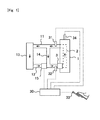
- Fig. 1 is a view showing the schematic construction of a cooling system for an internal combustion engine according to this embodiment of the present invention.
- An internal combustion engine 1 shown in Fig. 1 is a water cooled type internal combustion engine.
- a water jacket 2 for circulating cooling water is formed in the interior of the internal combustion engine 1.
- a first cooling water passage 11 and a second cooling water passage 12 are connected to the internal combustion engine 1.
- a radiator 13 and a bypass passage 14 are connected to these first cooling water passage 11 and second cooling water passage 12.
- the first cooling water passage 11 provides a connection between an outlet side of the water jacket 2 and an inlet side of the radiator 13. That is, the first cooling water passage 11 is a passage for discharging the cooling water from the water jacket 2.
- the second cooling water passage 12 provides a connection between an outlet side of the radiator 13 and an inlet side of the water jacket 2. That is, the second cooling water passage 12 is a passage for supplying the cooling water to the water jacket 2.
- a water pump 3 which serves to deliver the cooling water from the side of the second cooling water passage 12 to the side of the water jacket 2, is formed at a connection part between the second cooling water passage 12 and the water jacket 2.
- the bypass passage 14 serves to place the first cooling water passage 11 and the second cooling water passage 12 in communication with each other, thereby bypassing the radiator 13.
- a thermostat 15 of an electronic controlled type is arranged in the second cooling water passage 12 at a location near the radiator 13 from the connection part between the second cooling water passage 12 and the bypass passage 14.
- the degree of opening of this thermostat 15 is adjusted according to a signal from an ECU 30 which will be described later. Then, the amount of the cooling water supplied to the radiator 13 is adjusted by controlling the degree of opening of the thermostat 15.
- the cooling water having flowed out of the water jacket 2 into the first cooling water passage 11 is again sent to the water jacket 2 by way of the bypass passage 14.
- the cooling water is warmed in a gradual manner, so that the warming up of the internal combustion engine 1 is facilitated.
- the cooling water circulates by way of the radiator 13 and the bypass passage 14.
- the cooling water also circulates to those parts other than the radiator 13 and the bypass passage 14, which are omitted in Fig. 1 .
- an outlet side temperature sensor 31 which serves to measure the temperature of the cooling water flowing out of the water jacket 2 (hereinafter, referred to as an outlet side temperature), is mounted on the first cooling water passage 11 at a location between its connection part with the water jacket 2 and its connection part with the bypass passage 14.
- an inlet side temperature sensor 32 which serves to measure the temperature of the cooling water flowing into the water jacket 2 (hereinafter, referred to as an inlet side temperature) is mounted on the second cooling water passage 12 at a location between its connection part with the water jacket 2 and its connection part with the bypass passage 14.
- the ECU 30 which is an electronic control unit for controlling the internal combustion engine 1.
- This ECU 30 controls the internal combustion engine 1 in accordance with the operating conditions of the internal combustion engine 1 and/or driver's requirements.
- an accelerator opening sensor 33 which serves to detect an engine load by outputting an electrical signal corresponding to a degree of opening (i.e., an amount of depression) of an accelerator pedal
- a crank position sensor 34 which serves to detect the number of revolutions per minute of the engine
- the thermostat 15 is connected to the ECU 30 through electrical wiring, so that this thermostat 15 is controlled by the ECU 30.
- the cooling water in this embodiment has a specific heat which changes at a predetermined temperature.
- the cooling water is composed of including a substance which performs a phase transition from a solid to a liquid or from a liquid to a solid, at the predetermined temperature. That is, when the temperature of the cooling water becomes the predetermined temperature in the process of becoming higher, the substance included in the cooling water will change from a solid to a liquid, and at this time, will absorb heat from the surroundings. On the other hand, when the temperature of the cooling water becomes the predetermined temperature in the process of becoming lower, the substance included in the cooling water will change from a liquid to a solid, and at this time, will release heat to the surroundings. In this manner, at the time when a phase transition is carried out between a liquid and a solid, the specific heat of the cooling water changes.
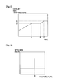
- Fig. 2 is a time chart showing the change over time of the outlet side temperature at the time of warming up of the internal combustion engine 1.
- the outlet side temperature of the cooling water becomes constant at a predetermined temperature D.
- the outlet side temperature of the cooling water becomes an opening temperature E of the thermostat 15, and so the thermostat 15 is open.
- the cooling water flows through the radiator 13, so that the outlet side temperature of the cooling water becomes substantially constant.
- Fig. 3 is a view showing the relation between the cooling water temperature and the specific heat of the cooling water.
- the specific heat of the cooling water becomes higher than that at other temperatures.
- the outlet side temperature of the cooling water becomes constant at the predetermined temperature D.
- Fig. 2 shows the case where the temperature E at which the thermostat 15 opens is higher than the predetermined temperature D.
- the thermostat 15 is set to open at the time when the outlet side temperature of the cooling water is higher than the predetermined temperature D, it will be possible to utilize the characteristic that the specific heat of the cooling water becomes higher, i.e., the characteristic of the cooling water temperature becoming constant. That is, when the cooling water temperature goes up, the rise of the temperature can be suppressed by taking heat, whereas when the cooling water temperature goes down, the fall of the temperature can be suppressed by giving heat. For this reason, the variation of the cooling water temperature can be suppressed, thus making it possible to stabilize the operating state of the internal combustion engine 1.
- the temperature E at which the thermostat 15 is opened may also be set, for example, as a temperature at which the warming up of the internal combustion engine 1 is completed, but is not limited to this.
- the components included in the cooling water may be decided in such a manner that the predetermined temperature D becomes lower than the temperature at which the warming up of the internal combustion engine 1 is completed. An optimum value of the temperature E at which the thermostat 15 is opened and an optimum value of the predetermined temperature D can be obtained through experiments, etc.
- the thermostat 15 is controlled by the ECU 30, but a thermostat which is automatically opened and closed at a prescribed temperature can also be used.
- the time at which the thermostat 15 is opened can also be set, in further consideration of the inlet side temperature, i.e., the temperature of the cooling water which flows through the second cooling water passage 12. That is, in an operating state in which a high cooling capacity is required, the thermostat 15 is set to open at the time when the inlet side temperature of the cooling water is lower than the predetermined temperature D. On the other hand, in an operating state in which the cooling capacity may be low, the thermostat 15 is set to open at the time when the inlet side temperature of the cooling water is higher than the predetermined temperature D.
- the operating state in which a high cooling capacity is required is, for example, in a state where at least one of the number of engine revolutions per minute and the engine load is relatively high. This may also be a time in which the internal combustion engine is at high rotation speed and under high load or in an accelerating operation.
- the operating state in which the cooling capacity may be low is, for example, in a state where the number of engine revolutions per minute and the engine load are relatively low. This may also be a time in which the internal combustion engine is at low rotation speed and under low load or in a steady state operation.
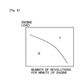
- Fig. 4 is a view showing the relation among the number of engine revolutions per minute, the engine load, and the temperature at which the thermostat 15 opens.
- F indicates an operation region in which a high cooling capacity is required (a region in which at least one of the number of engine revolutions per minute and the engine load is relatively high)
- G indicates an operation region in which the cooling capacity may be low (a region in which the number of engine revolutions per unit time and the engine load are relatively low).
- the thermostat 15 is opened so that the following relation is satisfied.
- the cooling water becomes the predetermined temperature D when it flows through the water jacket 2. Accordingly, the specific heat of the cooling water becomes high in the interior of the internal combustion engine 1, so the temperature rise of the cooling water in the interior of the internal combustion engine 1 can be suppressed. As a result of this, the operating state of the internal combustion engine 1 can be stabilized.
- the thermostat 15 is opened so that the following relation is satisfied.
- the predetermined temperature D ⁇ the inlet side temperature ⁇ the outlet side temperature That is, the inlet side temperature becomes higher than the predetermined temperature D.
- the cooling water temperature is maintained in a high state, thus making it possible to improve fuel economy.
- a boundary between the region indicated by F in Fig. 4 and the region indicated by G changes, for example, according to whether priority is given to the stability of the operating state of the internal combustion engine 1, or the improvement in fuel economy, and hence, an optimum value is obtained through experiments, etc.
Landscapes
- Engineering & Computer Science (AREA)
- Chemical & Material Sciences (AREA)
- Combustion & Propulsion (AREA)
- Mechanical Engineering (AREA)
- General Engineering & Computer Science (AREA)
- Combined Controls Of Internal Combustion Engines (AREA)
- Temperature-Responsive Valves (AREA)
Applications Claiming Priority (1)
| Application Number | Priority Date | Filing Date | Title |
|---|---|---|---|
| PCT/JP2010/069434 WO2012059969A1 (ja) | 2010-11-01 | 2010-11-01 | 内燃機関の冷却システム |
Publications (1)
| Publication Number | Publication Date |
|---|---|
| EP2636866A1 true EP2636866A1 (de) | 2013-09-11 |
Family
ID=46024102
Family Applications (1)
| Application Number | Title | Priority Date | Filing Date |
|---|---|---|---|
| EP10859226.2A Withdrawn EP2636866A1 (de) | 2010-11-01 | 2010-11-01 | Kühlsystem für einen verbrennungsmotor |
Country Status (5)
| Country | Link |
|---|---|
| US (1) | US20130220242A1 (de) |
| EP (1) | EP2636866A1 (de) |
| JP (1) | JP5500264B2 (de) |
| CN (1) | CN103180565A (de) |
| WO (1) | WO2012059969A1 (de) |
Families Citing this family (3)
| Publication number | Priority date | Publication date | Assignee | Title |
|---|---|---|---|---|
| JP5979030B2 (ja) * | 2013-02-05 | 2016-08-24 | マツダ株式会社 | 可変気筒エンジン |
| JP6572879B2 (ja) * | 2016-12-26 | 2019-09-11 | トヨタ自動車株式会社 | 内燃機関の冷却装置 |
| CN109281748A (zh) * | 2017-07-23 | 2019-01-29 | 黄义 | 内燃机y型进水管 |
Family Cites Families (29)
| Publication number | Priority date | Publication date | Assignee | Title |
|---|---|---|---|---|
| JPS56148610A (en) * | 1980-04-18 | 1981-11-18 | Toyota Motor Corp | Cooling device for engine |
| JPS59226225A (ja) * | 1983-06-08 | 1984-12-19 | Nissan Motor Co Ltd | 自動車用内燃機関の冷却水温制御装置 |
| US4546742A (en) * | 1984-01-23 | 1985-10-15 | Borg-Warner Corporation | Temperature control system for internal combustion engine |
| JPS6466413A (en) * | 1987-09-07 | 1989-03-13 | Mazda Motor | Cooling device for engine |
| DE4004936A1 (de) * | 1989-02-17 | 1990-08-23 | Aisin Seiki | Brennkraftmaschine mit einem wassergekuehlten zwischenkuehler |
| JP2767995B2 (ja) * | 1989-12-28 | 1998-06-25 | 株式会社デンソー | 内燃機関の冷却装置 |
| JP2712711B2 (ja) * | 1990-02-16 | 1998-02-16 | 株式会社デンソー | 内燃機関の冷却方法及びその装置 |
| DE69325044T2 (de) * | 1992-02-19 | 1999-09-30 | Honda Giken Kogyo K.K., Tokio/Tokyo | Maschinenkühlanlage |
| JP3039319B2 (ja) * | 1995-05-31 | 2000-05-08 | トヨタ自動車株式会社 | エンジンの冷却装置における冷却用電動ファンの制御装置 |
| JP4304782B2 (ja) * | 1999-08-31 | 2009-07-29 | マツダ株式会社 | エンジン冷却系におけるサーモスタットの故障診断装置 |
| FR2803334B1 (fr) * | 1999-12-30 | 2002-03-22 | Valeo Thermique Moteur Sa | Dispositif de regulation du refroidissement d'un moteur thermique de vehicule automobile dans un etat de demarrage a chaud |
| JP4522018B2 (ja) * | 2000-07-18 | 2010-08-11 | 本田技研工業株式会社 | 内燃機関の冷却構造 |
| DE10128423A1 (de) * | 2001-06-12 | 2003-01-02 | Bosch Gmbh Robert | Verfahren zum Überwachen eines Kühlflüssigkeitskreislaufs einer Brennkraftmaschine |
| JP3957531B2 (ja) * | 2002-03-08 | 2007-08-15 | トヨタ自動車株式会社 | エンジンの冷却装置 |
| DE10224063A1 (de) * | 2002-05-31 | 2003-12-11 | Daimler Chrysler Ag | Verfahren zur Wärmeregulierung einer Brennkraftmaschine für Fahrzeuge |
| JP3932277B2 (ja) * | 2002-10-18 | 2007-06-20 | 日本サーモスタット株式会社 | 電子制御サーモスタットの制御方法 |
| JP2004353602A (ja) | 2003-05-30 | 2004-12-16 | Nippon Thermostat Co Ltd | 電子制御サーモスタットの制御方法 |
| DE10337412A1 (de) * | 2003-08-14 | 2005-03-10 | Daimler Chrysler Ag | Verfahren zur Ansteuerung eines Thermostaten |
| DE10337413A1 (de) * | 2003-08-14 | 2005-03-10 | Daimler Chrysler Ag | Verfahren zur Regulierung des Kühlmittelflusses mit einem Heizungsabsperrventil |
| US7267086B2 (en) * | 2005-02-23 | 2007-09-11 | Emp Advanced Development, Llc | Thermal management system and method for a heat producing system |
| JP2006240501A (ja) * | 2005-03-03 | 2006-09-14 | Nissan Motor Co Ltd | ハイブリッド車用の冷却システム |
| US7347168B2 (en) * | 2006-05-15 | 2008-03-25 | Freightliner Llc | Predictive auxiliary load management (PALM) control apparatus and method |
| JP2007321633A (ja) * | 2006-05-31 | 2007-12-13 | Nissan Motor Co Ltd | 車両用冷却装置および車両用熱源の冷却方法 |
| JP4277046B2 (ja) * | 2007-02-28 | 2009-06-10 | トヨタ自動車株式会社 | 内燃機関の冷却装置 |
| JP2009044896A (ja) * | 2007-08-10 | 2009-02-26 | Nissan Motor Co Ltd | 車両用冷却装置 |
| JP4384230B2 (ja) * | 2008-03-19 | 2009-12-16 | ダイハツ工業株式会社 | エンジンの冷却装置 |
| JP4456162B2 (ja) * | 2008-04-11 | 2010-04-28 | 株式会社山田製作所 | エンジンの冷却装置 |
| JP5604834B2 (ja) | 2008-12-25 | 2014-10-15 | トヨタ自動車株式会社 | 吸・放熱カプセル及び吸・放熱カプセル分散液 |
| JP5481867B2 (ja) * | 2009-01-27 | 2014-04-23 | 日産自動車株式会社 | エンジン用冷却システム |
-
2010
- 2010-11-01 EP EP10859226.2A patent/EP2636866A1/de not_active Withdrawn
- 2010-11-01 WO PCT/JP2010/069434 patent/WO2012059969A1/ja not_active Ceased
- 2010-11-01 JP JP2012541643A patent/JP5500264B2/ja not_active Expired - Fee Related
- 2010-11-01 US US13/882,357 patent/US20130220242A1/en not_active Abandoned
- 2010-11-01 CN CN2010800698193A patent/CN103180565A/zh active Pending
Non-Patent Citations (1)
| Title |
|---|
| See references of WO2012059969A1 * |
Also Published As
| Publication number | Publication date |
|---|---|
| CN103180565A (zh) | 2013-06-26 |
| JPWO2012059969A1 (ja) | 2014-05-12 |
| JP5500264B2 (ja) | 2014-05-21 |
| US20130220242A1 (en) | 2013-08-29 |
| WO2012059969A1 (ja) | 2012-05-10 |
Similar Documents
| Publication | Publication Date | Title |
|---|---|---|
| US9188051B1 (en) | System and method of thermal management for an engine | |
| CN104018927B (zh) | 用于具有液体冷却型汽缸盖和液体冷却型汽缸体的内燃发动机的方法和系统 | |
| US7721683B2 (en) | Integrated engine thermal management | |
| US8863704B2 (en) | Liquid-cooled internal combustion engine and method for operating an internal combustion engine of said type | |
| EP2873826B1 (de) | Wärmespeicher in Motorkühlsystem | |
| CN106150715B (zh) | 内燃机的控制装置 | |
| EP3103981A1 (de) | Wärmeaustauschvorrichtung eines fahrzeugs | |
| EP1918545A2 (de) | Kühlmittelregler für einen Verbrennungsmotor | |
| US9850802B2 (en) | Coolant control device | |
| EP2703617A1 (de) | Steuerungsvorrichtung für die kühltemperatur eines verbrennungsmotors | |
| US10794336B2 (en) | Methods and systems for an exhaust gas recirculation cooler | |
| JP6319018B2 (ja) | エンジンの冷却システム | |
| EP2636866A1 (de) | Kühlsystem für einen verbrennungsmotor | |
| US10655529B2 (en) | Engine system | |
| JP7193327B2 (ja) | 車両用システムの制御装置 | |
| JP2011149385A (ja) | 冷却水循環装置 | |
| JP5682634B2 (ja) | 内燃機関の冷却システム | |
| JP2006348793A (ja) | 内燃機関の排気還流装置 | |
| JP4976908B2 (ja) | 流量可変ウォータポンプの制御装置 | |
| EP3059411A1 (de) | Kühlvorrichtung für einen verbrennungsmotor | |
| JP6738237B2 (ja) | 冷却装置 | |
| JP5880325B2 (ja) | 内燃機関の制御装置 | |
| JP2012102628A (ja) | 内燃機関の冷却システム | |
| JP2013068169A (ja) | 内燃機関の冷却装置 | |
| JP2008267246A (ja) | 内燃機関の冷却装置 |
Legal Events
| Date | Code | Title | Description |
|---|---|---|---|
| PUAI | Public reference made under article 153(3) epc to a published international application that has entered the european phase |
Free format text: ORIGINAL CODE: 0009012 |
|
| 17P | Request for examination filed |
Effective date: 20130531 |
|
| AK | Designated contracting states |
Kind code of ref document: A1 Designated state(s): AL AT BE BG CH CY CZ DE DK EE ES FI FR GB GR HR HU IE IS IT LI LT LU LV MC MK MT NL NO PL PT RO RS SE SI SK SM TR |
|
| DAX | Request for extension of the european patent (deleted) | ||
| STAA | Information on the status of an ep patent application or granted ep patent |
Free format text: STATUS: THE APPLICATION HAS BEEN WITHDRAWN |
|
| 18W | Application withdrawn |
Effective date: 20150326 |