EP2637361B1 - Procédé de détermination de la topologie d'un bus de données asynchrone en série - Google Patents
Procédé de détermination de la topologie d'un bus de données asynchrone en série Download PDFInfo
- Publication number
- EP2637361B1 EP2637361B1 EP13155875.1A EP13155875A EP2637361B1 EP 2637361 B1 EP2637361 B1 EP 2637361B1 EP 13155875 A EP13155875 A EP 13155875A EP 2637361 B1 EP2637361 B1 EP 2637361B1
- Authority
- EP
- European Patent Office
- Prior art keywords
- bus
- time
- telegram
- response
- slave
- Prior art date
- Legal status (The legal status is an assumption and is not a legal conclusion. Google has not performed a legal analysis and makes no representation as to the accuracy of the status listed.)
- Active
Links
Images



Classifications
-
- G—PHYSICS
- G06—COMPUTING OR CALCULATING; COUNTING
- G06F—ELECTRIC DIGITAL DATA PROCESSING
- G06F13/00—Interconnection of, or transfer of information or other signals between, memories, input/output devices or central processing units
- G06F13/38—Information transfer, e.g. on bus
- G06F13/42—Bus transfer protocol, e.g. handshake; Synchronisation
- G06F13/4282—Bus transfer protocol, e.g. handshake; Synchronisation on a serial bus, e.g. I2C bus, SPI bus
- G06F13/4295—Bus transfer protocol, e.g. handshake; Synchronisation on a serial bus, e.g. I2C bus, SPI bus using an embedded synchronisation
-
- H—ELECTRICITY
- H04—ELECTRIC COMMUNICATION TECHNIQUE
- H04L—TRANSMISSION OF DIGITAL INFORMATION, e.g. TELEGRAPHIC COMMUNICATION
- H04L12/00—Data switching networks
- H04L12/28—Data switching networks characterised by path configuration, e.g. LAN [Local Area Networks] or WAN [Wide Area Networks]
- H04L12/40—Bus networks
- H04L12/40052—High-speed IEEE 1394 serial bus
- H04L12/40078—Bus configuration
-
- H—ELECTRICITY
- H04—ELECTRIC COMMUNICATION TECHNIQUE
- H04L—TRANSMISSION OF DIGITAL INFORMATION, e.g. TELEGRAPHIC COMMUNICATION
- H04L12/00—Data switching networks
- H04L12/28—Data switching networks characterised by path configuration, e.g. LAN [Local Area Networks] or WAN [Wide Area Networks]
- H04L12/40—Bus networks
- H04L12/40052—High-speed IEEE 1394 serial bus
- H04L12/40084—Bus arbitration
-
- H—ELECTRICITY
- H04—ELECTRIC COMMUNICATION TECHNIQUE
- H04L—TRANSMISSION OF DIGITAL INFORMATION, e.g. TELEGRAPHIC COMMUNICATION
- H04L12/00—Data switching networks
- H04L12/28—Data switching networks characterised by path configuration, e.g. LAN [Local Area Networks] or WAN [Wide Area Networks]
- H04L12/40—Bus networks
- H04L12/4013—Management of data rate on the bus
- H04L12/40136—Nodes adapting their rate to the physical link properties
Definitions
- the invention relates to a method for determining the topology of a serial asynchronous data bus, to which at least a first bus subscriber and a second bus subscriber are connected, which communicate via a predetermined bus access protocol.
- the invention is fundamentally applicable to all serial data buses, in particular fieldbus systems such as PROFIBUS, Fieldbus Foundation, but also Ethernet and other known fieldbus systems.
- a fieldbus connects in a system field devices such as sensors and actuators, also referred to as slaves, for communication and control with a control device, also referred to as master. Since several users send messages over the same line, a standardized bus access protocol is defined for each fieldbus system.
- a fieldbus system comprises at least one master field device (master) for controlling the system and a plurality of slave field devices (slaves). Each bus participant is addressed by an assigned unique address. Communication in a fieldbus system takes place via bus-specific telegrams or data packets or data frames, whereby the master usually controls the communication and sends request telegrams to which the slaves react with response telegrams.
- a PROFIBUS DP network can have up to 127 subscribers, whereby up to 32 subscribers can be connected to individual bus segments of a bus line. Within the network, the individual bus segments are connected by means of line drivers, so-called repeaters.
- line drivers so-called repeaters.
- the network topology of the bus system i. the arrangement of the bus segments and the participants in the individual bus segments, is known.
- the connected devices should be considered in the order of their distance from the meter when considering the signal quality so that the correct location of the fault can be determined.
- the topology of the fieldbus should be known, because measurements are best carried out by the ends and the middle of the individual bus segments. If the order and length of the bus segments and the connection points of the devices to the segments are not known, a measurement can not be reasonably planned.
- the bus topology can be detected on the basis of DC measurements by gradually targeted the individual bus participants and the length of the line from the measuring point to the bus subscriber on the DC resistance of the line is determined. This method provides only inaccurate results, because unknown factors such as the contact resistance between plugs and cables, distort the measurement result.
- a more precise known measuring method is reflection-based transit time measurement, which determines the cable length depending on the known propagation speed of the measuring signals.
- These reflection measurement methods are active measurement methods, i. they actively send signals to the bus and detect the reflected signals. This means that the measuring methods are only executed on the stationary bus, if possible, because the transmitted test signals would disturb the ongoing operation of the fieldbus.
- methods which actively perform measurements during regular bus operation by taking advantage of the transmission pauses provided by the bus access protocol for the measurement; However, these methods always involve the risk that the transmitted signals still disturb the communication.
- a method for determining the network topology of a bus system in which each bus subscriber an initiating measurement telegram is sent to which a diagnostic repeater that connects multiple bus segments responds with a segment identifier and the other bus users respond with a response telegram, the diagnostic Repeater also sends a measurement signal to the responding bus participants, which is reflected by this, and from the period between the transmission of the measurement signal and the arrival of the reflection signals, the distance of the responding bus participants is determined by the diagnostic repeater.
- this method basically uses the transit time of the measurement signal which is impressed on the response telegram of the slave.
- a transmitting slave acts as an impedance at which the measurement signal is reflected.
- the diagnostic repeater thus waits until it receives the response telegram of the slave. At this point, the slave is still transmitting, since the signal propagation times are shorter than the transmission time of the telegram. A time window within the telegram in which the level does not change is then used for the reflection process.
- the method is a pure reflection method and is well suited for lower baud rates. At higher baud rates, the time window for measurement becomes very small and therefore the measurement becomes unreliable.
- the DE 100 48 741 C1 and the DE 10 2005 055 429 A1 also describe methods and devices for line diagnosis of a bus system according to the principle of reflection measurement.
- the DE 10 2010 000 249 A1 The applicant describes a method for checking the electrical properties of a cable of a fieldbus system, which method is based on changing the wiring of the fieldbus for the individual measurements.
- a configurable switching device is provided, which can be connected to the bus.
- the diagnostic methods for determining the bus topology of the prior art are thus based almost exclusively on reflection measurements. The only exception is the method for measuring the electrical resistance of the line. Most reflectance measurements and the electrical process require a quiescent bus. These measurements can therefore not be carried out during operation. The accuracy of the reflection measurement decreases with increasing baud rate of the data transmission.
- Another type of diagnostic method for a fieldbus system is known from DE 10 2006 051 144 A1 known. This method is less for the determination of the bus topology than the determination of states of the bus subscribers by detecting and analyzing the data packets exchanged on the bus and by step by step deriving the states of the bus participants in the manner of a state machine
- US patent discloses US 7,308,517 B1 a method for improving the performance of a high-speed serial bus.
- the invention has for its object to provide a method for determining the topology of a serial asynchronous data bus, which avoids the disadvantages of the prior art described above and allows a reliable determination of the topology, without having to interrupt the ongoing operation of the data bus or disturb ,
- the invention provides a method for determining the topology of a serial asynchronous data bus, wherein at least a first bus subscriber and a second bus subscriber are connected to the data bus, which communicate via a predetermined bus access protocol.
- the protocol includes defined request and response telegrams.
- the invention relates to a field bus system to which at least one master device as the first bus subscriber and several slave devices are connected as a second bus subscriber.
- the first bus user eg the master, sends request telegrams that are received by the second bus user, eg a slave. This sends in response to each request telegram each a response telegram, and the response telegrams are in turn received by the first bus subscriber.
- the time differences between receiving a respective request telegram of the first bus subscriber and receiving the associated response telegram of the second bus subscriber at a first measuring point on the data bus are determined, resulting from the time delays between response and request telegram at the measuring point (first multiplicity of temporal differences).
- the first measuring point can lie directly behind the first bus subscriber or, as seen by the second bus subscriber, behind the first bus subscriber.
- a first average response time is calculated from the first plurality of determined differences.
- the time differences between receiving the respective request telegram of the first bus subscriber and receiving the associated response telegram of the second bus subscriber at a second measuring point on the data bus determined (second plurality of time differences).
- the second measuring point can be located directly at the second bus subscriber or, viewed from the first bus subscriber, behind the second bus subscriber.
- a second average response time is calculated from the second plurality of determined differences. From the difference of the first average response time and the second average response time, the propagation delay and thus the distance between the first bus subscriber and the second bus subscriber can be derived according to the invention.
- the second average response time can be determined according to the same measurement principle in the same process cycle as the first average response time. Or it can be determined in advance for each second bus subscriber and stored in the form of an additional database. The advance determination of the average response time for the second bus subscriber can be carried out according to the method described above or according to another measuring principle.
- the first and second measuring points are preferably at the bus ends. The distances between the master and all slaves located between the two measuring points can then be determined.
- the invention is thus based on the determination of the average response times, which are measured from certain positions, and allows to determine therefrom the signal propagation times and thus the distance between bus subscribers.
- two series of measurements suffice to implement the invention.
- a measurement series is performed directly on the master, or as seen from the slaves behind the master, and a series of measurements is performed on or, viewed from the master, behind the last slave in the series.
- a series of measurements is carried out for each slave, in which the time differences of request and response telegram pairs assigned to this slave are detected and from this a mean response time is calculated for each slave, in each case from the point of view of the first one Measuring point and from the point of view of the second measuring point.
- the difference between the average response times at the two measurement positions allows the determination of the signal propagation time between the first bus user, eg the master, and every second bus user, eg the slaves.
- the measurements at the different measuring points need not be carried out synchronously, but they can be carried out successively using a measuring device which is connected in succession to the first and the second measuring point.
- the measurements do not have to be made directly at the first and second bus subscribers, e.g. be made on the master or on the slave. However, as stated above, the measurements should be outside the master-slave connection and on different sides of that connection.
- the cable lengths that are passed through equally from the request telegram and the response telegram to the meter are then cut out.
- it is sufficient to perform one measurement on the master and one measurement on or behind the last slave in the series. A measurement on each slave, however, is not necessary. If the average response times of the slaves have been determined in advance, it is sufficient to carry out a series of measurements at or near the master.
- the method according to the invention can be carried out during the current data traffic and evaluates the transmission and reception times of defined request and response telegrams which are regularly exchanged over the data bus.
- telegrams that are often sent to as many participants as possible.
- PROFIBUS these are, for example, the data exchange and the FDL (Fieldbus Data Layer) status telegrams.
- the data exchange telegrams are sent to every configured bus participant in each PROFIBUS cycle. Since the cycle times are often in the millisecond range, many measurements can be carried out in a short time.
- the FDL status telegram on the other hand, has the advantage that it is sent to every address is, has a fixed size and is often already answered by the hardware of the bus station. This makes it possible to record all devices and the response times are generally less widely dispersed than in the more complex telegram types. However, according to the invention it is also possible to base the method on other types of telegrams.
- T L T ⁇ r e s ⁇ 1 - T ⁇ r e s ⁇ 2 2 .
- T res 1 the aforementioned first average response time
- T res 2 the aforementioned second average response time.
- the sequence of the slave devices along the data bus can be determined directly from the propagation delays between the master device and the multiple slave devices. If the same or almost the same runtime is determined for several slave devices, this is an indication of a data bus branch.
- the following further method steps are then carried out: determining a plurality of time differences for a slave device between receiving request telegrams and transmitting associated response telegrams at a third measuring point on the data bus associated with the slave device, wherein the third point of measurement is behind the data bus branch on the slave device or, as seen from the master device, behind the slave device, and calculating an average response time associated with the slave device that is in the data bus branch from the slave device Variety of differences for the slave device.
- the second, third and each further measuring point is preferably always arranged at the end of the respective branching bus segment.
- all measurements are preferably carried out under the same operating conditions with regard to the state and physical parameters of the data bus.
- the inventive method can increase the accuracy of the distance determination by increasingly more measurements.
- the first and second mean values are each derived from at least 20 response times, but preferably from at least 50 or even at least 100 response times. It is also possible first to form the first and second average from only relatively few response times and to refine the averaging as the measurement duration and the acquisition of additional response times progresses.
- this bit time is just 83 ns at a baud rate of 12 MB, while the bit time is already 667 ns at a baud rate of 1.5 MB and is correspondingly higher at lower baud rates.
- a data propagation speed that is about 60% of the speed of light, ie 4.3 ns / m
- a response time variation of one bit width at 12 Mbaud (83 ns) corresponds to about 19 m and 1.5 Mbaud (667 ns) ) about 155 m. Even from this simple comparison, it can be seen that the invention should achieve more accurate measurements with higher transmission rates.
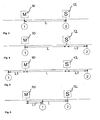
- a network consists of a master 10 (as an example of a first bus subscriber) and a slave 12 (as an example of a second bus subscriber) which are connected to each other via a cable of length L, this is in Fig. 1 shown.
- the request telegram is sent out by the master 10 and received by the slave after the runtime T L. After a certain delay time (T res (slave)), this sends the response which arrives at the master after the same time T L. This is in Fig. 2 illustrated.
- T res (slave) the response time the slave takes after receiving the telegram until it sends the response.
- the invention provides a method which records different signals at different times with successive measurements on the master and on or behind one or more slaves and determines the transit time and thus the distance between master and slave by evaluating the difference between the average response times. If the temporal fluctuations of the response times are statistically distributed, the deviation of the mean value decreases with the number of measurements.
- delays of the measuring devices as well as systematic and statistically distributed fluctuations of the response times of the second bus subscribers, e.g. Slaves, to be filtered out.
- a measurement setup on a data bus with line topology which has a master 10 and a slave 12, may be constructed.
- the two measuring points (1) and (2) need not be arranged directly on the master 10 or on the slave 12. It is sufficient if the measuring points (1) and (2) are arranged on the two sides of the connection between master 10 and slave 12.
- the Measuring structures of Fig. 3, 4 and 5 provide the same result in the method according to the invention.
- Both measuring points (1) and (2) are arranged directly on the master 10 or on the slave 12.
- the average response time is determined, which is assigned to the first bus user (master)
- the average response time is determined, which is assigned to the second bus subscriber (slave).
- the average response time of the slave MW T res (slave)
- the result is twice the runtime.
- the measuring point (2) seen from the master 10 from behind the slave 12, and in measuring construction of the Fig. 5
- the measuring point (1) from the perspective of the slave 12 is arranged behind the master.
- the signals emitted by the master 10 and by the slave 12 arrive delayed at the measuring point (2) so that the same average response time of the slave 12 is measured at the measuring point (2) as in the structure of FIG Fig. 3 ,
- the measured response time does not change if the measurement location is moved to a position outside the connection between master 10 and slave 12 and is located on different sides of the master and slave. How about the Fig. 7 to 10 is explained, this can be exploited to determine the average response times of multiple slaves with one and the same measurement setup.
- Fig. 7 For example, an exemplary topology is illustrated to illustrate that not only line topologies but also branched topologies can be determined with the invention.
- the bus network includes a master 10, 8 slaves 12, denoted S1 through S8, and two repeater stations 14, labeled R1 and R2.
- the total topology is determined sequentially at all bus ends to determine the overall topology.
- the measuring locations (1) to (4) are represented by circles at the respective bus ends.
- the example network consists of three physical segments 20, 22, 24 with one master 12, two repeater stations 14, for example diagnostic repeaters with their own address, and the total of eight slaves 12.
- four bus terminations 30, 32, 34, 36 are provided. which simultaneously serve as measuring positions (1) to (4).
- the main segment 20 consists of the master M and the four slaves S 1 to S4.
- the two comb-shaped branching secondary segments 22, 24 are connected to the main segment 20 via the repeaters R1 and R2.
- the repeater R1 is arranged directly on the slave S1.
- the repeater R2 is connected at a distance d from the slave S3 to the main segment 20.
- the entire topology can be determined with four measurement series, as explained below.
- two series of measurements at the two ends 30, 32 of the main segment 20, at the measuring positions (1) and (2) are performed.
- the distances between the master M and the slaves S1, S2, S3 and S4 can be determined.
- the average response times of the slaves S 1 to S 4 are determined from the perspective of the master, and in the second series of measurements at the measurement position (2), the average response times of the slaves S1, S2, S3 and S4 determined directly, ie without the additional propagation delay between master and Slaves.
- the run times and thus the distances between the master and the individual slaves can then be calculated.
- the slaves S5 to S8 which lie on the secondary segments 22, 24 of the data bus.
- the distance of the associated branch is also determined, ie the distance of the slave S3 plus the distance d. From the agreement of the distances for the slaves S5 and S6, it can first be concluded that they lie on a secondary segment. The same applies to the slaves S7 and S8. The distances determined for these slaves thus result in each case the distance from the master M to the associated branching of the secondary segment 22, 24.
- the series of measurements at the measuring points (1) and (2) results in the Fig. 8 shown topology image. The stations drawn above each have the same calculated distance to the master M.
- repeater station R1 The repeater functionality of repeater station R1 can not be detected directly by the measurement. This repeater station R1 makes itself felt by an additional propagation delay and, if the repeater station is not known, by a greater distance to the slaves S5 and S6.
- Fig. 10 shows the topology image that results after performing measurements on all four measurement positions (1) to (4).
- N + 1 measurement data sets are derived for determining the overall topology of a data bus with N segments.
- N x (N + 1) / 2 pairs of measurements are evaluated.
- the true distance of a slave from the master is the maximum of all detected distances for that slave.
- a smaller than the maximum distance for a slave gives an indication of the distance of a branch of a bus segment on which the slave is located.
- this is also the case an indication that these slaves are in the same subsegment with respect to the two measuring positions or are located directly at the branch.
- the final distance vector then results from the maximum of all distances determined for the slaves: L ⁇ 1 L ⁇ 2 L ⁇ 3 L ⁇ 4 L ⁇ 5 L ⁇ 6 L ⁇ 7 L ⁇ 8th
- the method according to the invention can use a topology image which brings the determined range vectors into a form suitable for displaying the topology.
- M telegram pairs that is to say request and response telegrams
- M 100.
- the observed telegram pairs are data exchange telegrams, these are converted, for example, into a PROFIBUS network once per input / output cycle, the duration of an input-output cycle may be on the order of 10 to 100 ms. If, for example, 30 slaves are connected in line to the fieldbus system, a response time per slave can be determined within 300 to 3000 ms under this condition.
- the required measurement time at each measurement point is approximately 0.5 to 5 minutes.
- the measurement does not intervene in the data exchange on the fieldbus, but monitors the data traffic on, for example, the data exchange telegrams.
- Fig. 11 and 12 show exemplary flow diagrams for performing a first and a second series of measurements for detecting response times at the master or on the slave. To the right of the flowchart, the individual events are shown on a timeline, but this is not to scale.
- the counter is used to determine the number of response times to be included in the averaging.
- a master sends a request telegram (step 42) to a slave device, which is received by a measuring device virtually at the same time.
- the measuring device at the measuring point which is assigned to the master device, generates on its next clock edge a first time stamp Z S (master).
- T L which depends on the distance between master and slave
- the slave device receives in step 46 the request telegram.
- the request telegram has a predetermined length of x bit times, in the case of the FDL status telegram according to the PROFIBUS standard 66 bit times. Furthermore, a minimum wait time is defined for each slave before it can send a response; this is 11 bit times in the selected embodiment of the PROFIBUS standard.
- the slave sends in a next step 48 at a time T S (slave), the earliest 77 bit times after the reception time T E (slave) is in the selected embodiment, an answer telegram. This is received by the master after the propagation time T L at a reception time T E (master) (step 50). Practically at the same time, the measuring device also receives the response telegram and generates on its next clock edge a second time stamp Z E (master) in step 52.
- step 56 it is checked whether a predetermined number of measurements has already been performed; ie m ⁇ M?, where M is 100, for example. If not, the measurement loop goes back to step 42 to observe another input / output cycle. If a sufficient number of measurements have taken place, then the recorded transmission and reception times at the master or the corresponding time stamps Z S (master) and Z E (master) of the measuring device for calculating the average response times are transmitted in step 58. For averaging, a known mean algorithm, such as arithmetic mean, may be used.
- the meter When the measurement for one or more slave devices on the master is completed, the meter can be disconnected from the master and connected to or behind one of the slaves.
- the measuring procedure on the slave is in Fig. 12 shown.
- the measurement process begins when the slave receives the first defined request telegram at a time T E (slave), as shown in step 62.
- the measuring device also receives the telegram and in step 64 generates a first time stamp Z E (slave).
- the slave sends in step 66 after the complete reception of the request telegram and the defined waiting time, as explained above, at a time T S (slave) its response telegram. This is in turn received by the measuring device at the same time, which generates a second time stamp Z S (slave) in step 68.
- a query is made as to whether a predetermined number of measurements have already been taken, m ⁇ M?. If not, the meter goes through another measurement cycle and goes back to step 62. If so, the determined response times, Z S - Z E , are passed to an averaging algorithm, which is executed in step 76. The mean value is calculated in the same way as the average response time at the master. This completes the determination of the average response time of a slave.
- the average response times are then subtracted to master and slave to determine the propagation delay between master and slave.
- the timestamp generated by the meter should be sufficiently accurate and subject to no temporal drift, for example, temperature changes. Furthermore, the sampling rate of the meter should be sufficiently high, so that a high time resolution is guaranteed.
- bus state that is to say the overall state of the connected devices and their activities, does not change between the measurements.
- ambient temperature humidity and the like.
Landscapes
- Engineering & Computer Science (AREA)
- Computer Networks & Wireless Communication (AREA)
- Signal Processing (AREA)
- Theoretical Computer Science (AREA)
- Physics & Mathematics (AREA)
- General Engineering & Computer Science (AREA)
- General Physics & Mathematics (AREA)
- Quality & Reliability (AREA)
- Small-Scale Networks (AREA)
- Arrangements For Transmission Of Measured Signals (AREA)
Claims (14)
- Procédé de détermination de la topologie d'un bus de données série asynchrone auquel sont connectés au moins un premier abonné au bus (10) et un deuxième abonné au bus (12) qui communiquent au moyen d'un protocole d'accès au bus prédéfini qui comprend des télégrammes de demande et de réponse définis, comprenant les étapes de procédé suivantes :envoi de télégrammes de demande par le premier abonné au bus (10) et réception des télégrammes de demande au deuxième abonné au bus (12), etenvoi d'un télégramme de réponse par le deuxième abonné au bus (12) en réponse à chaque télégramme de demande et réception des télégrammes de réponse par le premier abonné au bus (10),caractérisé par les étapes suivantes :détermination d'une première pluralité de différences de temps entre la réception d'un télégramme de demande respectif du premier abonné au bus (10) et la réception du télégramme de réponse correspondant du deuxième abonné au bus (12) à un premier point de mesure (1) sur le bus de données,détermination d'une deuxième pluralité de différences de temps entre la réception du télégramme de demande respectif du premier abonné au bus (10) et la réception du télégramme de réponse correspondant du deuxième abonné au bus (12) à un deuxième point de mesure (2) sur le bus de données,le premier point de mesure (1) étant situé au niveau du premier abonné au bus (10) ou, vu du deuxième abonné au bus (12), derrière le premier abonné au bus (10), et le deuxième point de mesure (2) étant situé au niveau du deuxième abonné au bus (12) ou, vu du premier abonné au bus (10), derrière le deuxième abonné au bus (12),calcul d'un premier temps de réponse moyen
T res1 pour le deuxième abonné au bus (12) à partir de la première pluralité de différences de temps déterminée,calcul d'un deuxième temps de réponse moyenT res2 pour le deuxième abonné au bus (12) à partir de la deuxième pluralité de différences de temps déterminée,calcul d'un retard de propagation TL comme moitié de la différence entre le premier temps de réponse moyenT res1 et le deuxième temps de réponse moyenT res2 , une distance entre le premier abonné au bus (10) et le deuxième abonné au bus (12) pouvant en être déduite. - Procédé selon la revendication 1, selon lequel le deuxième point de mesure (2) est situé à une extrémité de bus (30, 32, 34, 36) derrière le dernier deuxième abonné au bus (12).
- Procédé selon la revendication 1 ou 2, selon lequel, pour déterminer la première pluralité de différences de temps entre la réception du télégramme de demande respectif du premier abonné au bus (10) et la réception du télégramme de réponse correspondant du deuxième abonné au bus (12) au premier point de mesure (1) et pour déterminer la deuxième pluralité de différences de temps entre la réception du télégramme de demande respectif du premier abonné au bus (10) et la réception du télégramme de réponse correspondant du deuxième abonné au bus (12) au deuxième point de mesure (2), on utilise le même appareil de mesure qui est connecté successivement au premier point de mesure (1) et au deuxième point de mesure (2).
- Procédé selon la revendication 2, selon lequel le premier abonné au bus (10), le deuxième abonné au bus (12) et l'appareil de mesure travaillent à des fréquences d'horloge propres, non synchronisées.
- Procédé selon l'une des revendications précédentes, selon lequel le deuxième temps de réponse moyen
T res2 pour le deuxième abonné au bus (12) est déterminé préalablement. - Procédé selon l'une des revendications précédentes, selon lequel le retard de propagation TL est calculé selon la formule suivante :

- Procédé selon l'une des revendications précédentes, selon lequel les télégrammes de demande et de réponse sont sélectionnés parmi un ou plusieurs des télégrammes suivants :télégrammes réguliers du protocole d'accès au bus échangés pendant un trafic de données régulier sur le bus de données, télégrammes d'échange de données échangés une fois dans chaque cycle d'entrée/sortie d'un abonné au bus et télégrammes d'état FDL.
- Procédé selon l'une des revendications précédentes, selon lequel le premier abonné au bus (10) est un appareil maître (M) et le deuxième abonné au bus (12) un appareil esclave (S1-S8) et selon lequel(a) l'appareil maître (M) envoie un télégramme de demande à l'appareil esclave (S1-S8) à un instant d'envoi To,(b) l'appareil de mesure au premier point de mesure (1) reçoit le télégramme de demande et génère sur un prochain flanc d'horloge un premier horodatage Zs,(c) l'appareil esclave (S1-S8) reçoit le télégramme de demande après un temps de propagation TL qui dépend de la distance entre l'appareil maître (M) et l'appareil esclave (S1-S8), lequel télégramme de demande présente une longueur de x temps de bit,(d) après la réception complète du télégramme de demande et un temps d'attente de y temps de bit, l'appareil esclave (S1-S8) envoie le télégramme de réponse,(e) l'appareil maître (M) reçoit, après le temps de propagation TL, le télégramme de réponse à un instant TE,(f) le premier appareil de mesure (1) reçoit le télégramme de réponse et génère sur son prochain flanc d'horloge un deuxième horodatage ZE, et(g) un temps de réponse Tres est déterminé à partir de la différence des deux horodatages (ZE, ZS), etles étapes (a) à (g) étant répétées plusieurs fois, les dispersions des temps de réponse qui résultent de fluctuations dans le temps d'attente de l'appareil esclave (S1-S8) étant compensées par un algorithme de valeur moyenne pour former le premier temps de réponse moyen
T res1 . - Procédé selon la revendication 8, selon lequel au bus de données sont connectés plusieurs appareils esclaves (S1-S8) qui échangent de manière répétée des télégrammes de demande et de réponse avec l'appareil maître (M).
- Procédé selon la revendication 9, selon lequel l'étape de détermination d'une première pluralité de différences de temps entre la réception d'un télégramme de demande respectif et la réception du télégramme de réponse correspondant au premier point de mesure (1) comprend une détermination des différences de temps de paires de télégrammes de demande et de réponse qui sont associées à différents appareils esclaves (S1-S8), et
l'étape de calcul du premier temps de réponse moyenT res1 comprenant le calcul d'un temps de réponse moyen pour chacun des appareils esclaves (S1-S8) à l'appareil maître. - Procédé selon la revendication 10, selon lequel, pour chacun des appareils esclaves (S1-S8), la différence entre le temps de réponse moyen correspondant à l'appareil maître (M) et le temps de réponse moyen associé à l'appareil esclave (S1-S8) respectif est calculé, et le retard de propagation TL respectif et donc la distance respective entre l'appareil maître (M) et chacun des appareils esclaves (S1-S8) sont déduits des différences respectives.
- Procédé selon la revendication 11, selon lequel un ordre des appareils esclaves (S1-S8) le long du bus de données ou d'une section de bus de données (20, 22, 24) à topologie linéaire est déterminé à partir des retards de propagation TL respectifs entre l'appareil maître (M) et les plusieurs appareils esclaves (S1-S8).
- Procédé selon la revendication 12, selon lequel, lorsque le même ou presque le même retard de propagation TL est déterminé pour plusieurs appareils esclaves (S1-S8), une bifurcation de bus de données est détectée et les étapes de procédé supplémentaires suivantes sont exécutées :détermination d'une troisième pluralité de différences de temps pour un appareil esclave (S1-S8) entre la réception de télégrammes de demande et la réception de télégrammes de réponse correspondants à un troisième point de mesure (3, 4) sur le bus de données, le troisième point de mesure (3, 4) étant situé derrière la bifurcation de bus de données (22, 24) au niveau de l'appareil esclave (S1-S8) ou, vu de l'appareil maître (M), derrière l'appareil esclave (S1-S8), etcalcul d'un troisième temps de réponse moyen
T res3 pour l'appareil esclave (S1-S8) situé dans la bifurcation de bus de données (22, 24) à partir de la troisième pluralité de différences de temps déterminée. - Procédé selon l'une des revendications précédentes, selon lequel la détermination de la première pluralité de différences de temps entre la réception du télégramme de demande respectif du premier abonné au bus (10) et la réception du télégramme de réponse correspondant du deuxième abonné au bus (12) au premier point de mesure (1), et la détermination de la deuxième ou troisième pluralité de différences de temps entre la réception du télégramme de demande respectif et la réception du télégramme de réponse correspondant à un deuxième ou troisième point de mesure (2, 3, 4) sont effectuées dans les mêmes conditions de service en termes d'état et de paramètres physiques du bus de données.
Applications Claiming Priority (1)
| Application Number | Priority Date | Filing Date | Title |
|---|---|---|---|
| DE102012101881A DE102012101881B4 (de) | 2012-03-06 | 2012-03-06 | Verfahren zur Bestimmung der Topologie eines seriellen asynchronen Datenbusses |
Publications (2)
| Publication Number | Publication Date |
|---|---|
| EP2637361A1 EP2637361A1 (fr) | 2013-09-11 |
| EP2637361B1 true EP2637361B1 (fr) | 2015-07-29 |
Family
ID=47900527
Family Applications (1)
| Application Number | Title | Priority Date | Filing Date |
|---|---|---|---|
| EP13155875.1A Active EP2637361B1 (fr) | 2012-03-06 | 2013-02-20 | Procédé de détermination de la topologie d'un bus de données asynchrone en série |
Country Status (3)
| Country | Link |
|---|---|
| US (1) | US9442880B2 (fr) |
| EP (1) | EP2637361B1 (fr) |
| DE (1) | DE102012101881B4 (fr) |
Families Citing this family (16)
| Publication number | Priority date | Publication date | Assignee | Title |
|---|---|---|---|---|
| KR101679465B1 (ko) * | 2013-05-13 | 2016-11-24 | 엘에스산전 주식회사 | 프로피버스 dp의 마스터 장치 |
| US20170070566A1 (en) * | 2014-02-24 | 2017-03-09 | Fts Computertechnik Gmbh | Method and computer network for transmitting messages |
| DE102014210505A1 (de) * | 2014-06-03 | 2015-12-03 | Robert Bosch Gmbh | Übertragungseinheit mit Prüffunktion |
| DE102014114883A1 (de) * | 2014-10-14 | 2016-04-14 | Beckhoff Automation Gmbh | Verfahren und System zum Überwachen eines ersten Teilnehmers eines Kommunikationsnetzwerks |
| DE102015212674A1 (de) * | 2015-07-07 | 2017-01-12 | Siemens Aktiengesellschaft | Wechsel zwischen Segmenten eines Netzwerks |
| US9385967B1 (en) | 2015-12-04 | 2016-07-05 | International Business Machines Corporation | Resource allocation for a storage area network |
| CN112136055A (zh) | 2018-03-19 | 2020-12-25 | 莱尼电缆有限公司 | 用于监测电缆的测量设备和方法 |
| EP3876428A4 (fr) * | 2018-12-20 | 2021-11-24 | Mitsubishi Electric Corporation | Système de calcul de longueur de câble, dispositif de commande, et procédé de calcul de longueur de câble |
| US11855817B2 (en) * | 2019-09-27 | 2023-12-26 | Axonne, Inc. | Wired communication system including asymmetrical physical layer devices |
| US11070409B2 (en) * | 2019-09-27 | 2021-07-20 | Axonne, Inc. | Wired communication system including asymmetrical physical layer devices |
| CN113033791B (zh) * | 2019-12-24 | 2024-04-05 | 中科寒武纪科技股份有限公司 | 用于保序的计算装置、集成电路装置、板卡及保序方法 |
| EP4142222B1 (fr) | 2020-04-30 | 2025-10-29 | KONE Corporation | Détermination d'une séquence de noeuds de bus dans un bus de communication multipoints |
| EP3905603A1 (fr) * | 2020-04-30 | 2021-11-03 | KONE Corporation | Détermination d'une séquence de n uds de bus dans un bus de communication multipoints |
| DE102022133731A1 (de) * | 2022-12-16 | 2024-06-27 | Endress+Hauser SE+Co. KG | Verfahren zur Informationsübertragung mittels eines 2-Leiter Messgeräts |
| DE102023131495A1 (de) * | 2023-11-13 | 2025-05-15 | Beckhoff Automation Gmbh | Verfahren zum ermitteln einer aufbaureihenfolge von busteilnehmern eines automatisierungsnetzwerks, verfahren zur steuerung einer mehrzahl an busteilnehmern eines automatisierungsnetzwerks, busteilnehmer und automatisierungsnetzwerk |
| CN117714298B (zh) * | 2023-12-18 | 2024-10-08 | 宁夏隆基宁光仪表股份有限公司 | 基于特征信号的低压台区拓扑网络识别方法和终端设备 |
Family Cites Families (36)
| Publication number | Priority date | Publication date | Assignee | Title |
|---|---|---|---|---|
| US4293857A (en) * | 1979-08-10 | 1981-10-06 | Baldwin Edwin L | Collision avoidance warning system |
| USH388H (en) * | 1984-12-31 | 1987-12-01 | Shell Oil Company | Apparatus and method for locating towed seismic floats |
| JP2896782B2 (ja) * | 1988-12-30 | 1999-05-31 | 株式会社トプコン | パルス方式の光波距離計 |
| US5778172A (en) * | 1996-04-22 | 1998-07-07 | Lockheed Martin Corporation | Enhanced real-time topology analysis system or high speed networks |
| DE19710971A1 (de) * | 1997-03-17 | 1998-09-24 | Siemens Ag | Verfahren zur Bestimmung der Laufzeit eines Telegramms sowie Teilnehmer zur Durchführung des Verfahrens |
| US6246361B1 (en) * | 1999-06-28 | 2001-06-12 | Gary Sutton | Method and apparatus for determining a geographical location of a mobile communication unit |
| US7075895B1 (en) * | 1998-12-04 | 2006-07-11 | Sun Microsystems, Inc. | System and method for facilitating discovery of network addresses and selected charateristics of computer systems and the like which are connected in digital data networks |
| JP4147689B2 (ja) * | 1999-06-14 | 2008-09-10 | ソニー株式会社 | 情報処理装置及び情報処理方法 |
| US7065584B1 (en) * | 2000-04-28 | 2006-06-20 | Lucent Technologies Inc. | Method and apparatus for network mapping using end-to-end delay measurements |
| DE10048741C1 (de) * | 2000-09-29 | 2002-01-10 | Siemens Ag | Verfahren und Vorrichtung zur Leitungsdiagnose eines Bussystems |
| DE10048745C1 (de) | 2000-09-29 | 2002-02-21 | Siemens Ag | Verfahren und Vorrichtung zur Ermittlung der Netztopologie eines Bussystems |
| US7937470B2 (en) * | 2000-12-21 | 2011-05-03 | Oracle International Corp. | Methods of determining communications protocol latency |
| US6959333B2 (en) * | 2001-05-08 | 2005-10-25 | Lucent Technologies Inc. | Technique for content delivery over the internet |
| US6879806B2 (en) * | 2001-06-01 | 2005-04-12 | Zensys A/S | System and a method for building routing tables and for routing signals in an automation system |
| US7633942B2 (en) * | 2001-10-15 | 2009-12-15 | Avaya Inc. | Network traffic generation and monitoring systems and methods for their use in testing frameworks for determining suitability of a network for target applications |
| US7054554B1 (en) * | 2001-11-02 | 2006-05-30 | Ciena Corporation | Method and system for detecting network elements in an optical communications network |
| KR100411134B1 (ko) * | 2001-11-27 | 2003-12-18 | 에스케이 텔레콤주식회사 | 멀티-프로토콜 레이블 스위칭 기반의 멀티 캐스트 라우팅프로토콜 설정 방법 |
| US6674687B2 (en) * | 2002-01-25 | 2004-01-06 | Navcom Technology, Inc. | System and method for navigation using two-way ultrasonic positioning |
| WO2003089950A2 (fr) * | 2002-04-15 | 2003-10-30 | Toolz, Ltd. | Dispositif de mesure de distance |
| US20040054776A1 (en) * | 2002-09-16 | 2004-03-18 | Finisar Corporation | Network expert analysis process |
| US7636321B1 (en) * | 2003-05-12 | 2009-12-22 | Sprint Communications Company L.P. | Method and system for measuring round-trip time of packets in a communications network |
| US7436780B2 (en) * | 2003-12-17 | 2008-10-14 | Time Warner, Inc. | Method and apparatus for approximating location of node attached to a network |
| US7308517B1 (en) * | 2003-12-29 | 2007-12-11 | Apple Inc. | Gap count analysis for a high speed serialized bus |
| JP4561329B2 (ja) * | 2004-11-18 | 2010-10-13 | ソニー株式会社 | 測距システム,送信端末,受信端末,測距方法,およびコンピュータプログラム |
| US20070100036A1 (en) | 2005-10-31 | 2007-05-03 | Optimax Technology Corporation | Optical film and method of manufacturing the same |
| DE102005055964A1 (de) * | 2005-11-15 | 2007-05-16 | Valeo Schalter & Sensoren Gmbh | Verfahren zum Betreiben eines Sensorsystems, Sensorsystem und Sensormodul |
| DE102005055429B4 (de) * | 2005-11-21 | 2011-12-22 | Siemens Ag | Verfahren und Vorrichtung zur Diagnose eines Bussystems mit einer Anzahl von Busteilnehmern |
| WO2007116361A2 (fr) * | 2006-04-07 | 2007-10-18 | Nxp B.V. | Systeme et procede de connexion de nœuds a un reseau heterogene sans L'utilisASTION D'un concept de pont |
| DE102006051444C5 (de) | 2006-10-31 | 2011-12-08 | Softing Ag | Diagnoseverfahren und -vorrichtung für ein Feldbussystem |
| US7773543B2 (en) * | 2006-12-14 | 2010-08-10 | Cirrus Logic, Inc. | Determining characteristics of node-to-node network links from forwarding time measurements |
| US8520721B2 (en) * | 2008-03-18 | 2013-08-27 | On-Ramp Wireless, Inc. | RSSI measurement mechanism in the presence of pulsed jammers |
| JP5173623B2 (ja) * | 2008-06-19 | 2013-04-03 | パナソニック株式会社 | 無線測距システム及び無線測距方法 |
| US8736482B2 (en) * | 2009-07-17 | 2014-05-27 | Saab Sensis Corporation | System and method for aircraft navigation using signals transmitted in the DME transponder frequency range |
| US8427969B1 (en) * | 2009-09-05 | 2013-04-23 | Applied Micro Circuits Corporation | System and method for calculating passive host proximity in an L2 link layer |
| DE102010000249A1 (de) * | 2010-01-28 | 2011-08-18 | Softing AG, 85540 | Verfahren und Einrichtung zum Überprüfen elektrischer Eigenschaften eines Kabels, Feldbussystem |
| US8732302B2 (en) * | 2011-07-15 | 2014-05-20 | Inetco Systems Limited | Method and system for monitoring performance of an application system |
-
2012
- 2012-03-06 DE DE102012101881A patent/DE102012101881B4/de not_active Expired - Fee Related
-
2013
- 2013-02-20 EP EP13155875.1A patent/EP2637361B1/fr active Active
- 2013-03-05 US US13/786,198 patent/US9442880B2/en active Active
Also Published As
| Publication number | Publication date |
|---|---|
| EP2637361A1 (fr) | 2013-09-11 |
| US9442880B2 (en) | 2016-09-13 |
| DE102012101881A1 (de) | 2013-09-12 |
| US20130254443A1 (en) | 2013-09-26 |
| DE102012101881B4 (de) | 2013-11-21 |
Similar Documents
| Publication | Publication Date | Title |
|---|---|---|
| EP2637361B1 (fr) | Procédé de détermination de la topologie d'un bus de données asynchrone en série | |
| DE102014106752B4 (de) | Verfahren und Steuereinrichtung zum Betrieb eines berührungslosen Übertragungssystems für einen IO-Link | |
| DE102010037221A1 (de) | Verfahren und Geräte zum Angleichen einer Regelkreiszeiteinstellung in einem Prozessregelsystem | |
| EP3022856B1 (fr) | Procede de localisation d'une deviation de frequence dans un reseau de communication et reseau de commmunication correspondant | |
| EP1810096B1 (fr) | Procede pour echanger des donnees entre des terminaux de differents reseaux | |
| DE102013218075A1 (de) | Vorrichtung und Messverfahren zur Ermittlung der internen Verzögerungszeit einer CAN-Busanschlusseinheit | |
| EP3353960B1 (fr) | Réseau de communication, procédé de fonctionnement associé et utilisateur dans un réseau de communication | |
| EP1659718A2 (fr) | Procédé de synchronisation, système de régulation pour la synchronisation d'unités secondaires et unités secondaires synchronisables | |
| EP3526930B1 (fr) | Procédé de surveillance d'un réseau pour des anomalies | |
| WO2016037645A1 (fr) | Procédé de détermination du temps de transmission d'un télégramme dans un réseau de communication et composants de réseau correspondants | |
| DE102010000249A1 (de) | Verfahren und Einrichtung zum Überprüfen elektrischer Eigenschaften eines Kabels, Feldbussystem | |
| EP1315337B1 (fr) | Interface du bus | |
| DE68919674T2 (de) | Verfahren und Gerät zur Diagnose von Netzwerken. | |
| EP3032779B1 (fr) | Procede de determination de la qualite de signal dans un reseau faisant appel a un protocole can | |
| EP2299614B1 (fr) | Dispositif et procédé de synchronisation temporelle dans un réseau de communication | |
| EP1955491B1 (fr) | Procédé et dispositif pour coupler au moins deux systèmes de bus indépendants | |
| DE102005055429B4 (de) | Verfahren und Vorrichtung zur Diagnose eines Bussystems mit einer Anzahl von Busteilnehmern | |
| EP2713227A1 (fr) | Système et procédé de commande et/ou surveillance de procédés techniques dans un système d'automatisation industriel | |
| EP2079176A1 (fr) | Dispositif de communication et procédé de transmission de données | |
| AT518674B1 (de) | Verfahren zur synchronisierten Erfassung von zur Steuerung von Differentialschutzeinrichtungen elektrischer Energieleitungen benötigten Messdaten | |
| EP2338248B1 (fr) | Procédé pour exploiter un système de communication à plusieurs n uds et système de communication associé | |
| DE10241429B4 (de) | Verfahren zur Synchronisation von Netzwerkknoten eines Teilnetzwerks | |
| EP1497735A2 (fr) | Procede et dispositif d'inspection d'une fonction de surveillance d'un systeme de bus et systeme de bus | |
| EP4327178B1 (fr) | Dispositif et procédé de surveillance assistée par ordinateur de deux bases temporelles de deux dispositifs de communication | |
| EP1408386B1 (fr) | Procédé et dispositif de transfer de données entre une unité de traitement et plusieurs capteurs de position |
Legal Events
| Date | Code | Title | Description |
|---|---|---|---|
| PUAI | Public reference made under article 153(3) epc to a published international application that has entered the european phase |
Free format text: ORIGINAL CODE: 0009012 |
|
| AK | Designated contracting states |
Kind code of ref document: A1 Designated state(s): AL AT BE BG CH CY CZ DE DK EE ES FI FR GB GR HR HU IE IS IT LI LT LU LV MC MK MT NL NO PL PT RO RS SE SI SK SM TR |
|
| AX | Request for extension of the european patent |
Extension state: BA ME |
|
| 17P | Request for examination filed |
Effective date: 20140311 |
|
| RBV | Designated contracting states (corrected) |
Designated state(s): AL AT BE BG CH CY CZ DE DK EE ES FI FR GB GR HR HU IE IS IT LI LT LU LV MC MK MT NL NO PL PT RO RS SE SI SK SM TR |
|
| RIC1 | Information provided on ipc code assigned before grant |
Ipc: H04L 12/40 20060101AFI20140827BHEP |
|
| 17Q | First examination report despatched |
Effective date: 20140915 |
|
| GRAP | Despatch of communication of intention to grant a patent |
Free format text: ORIGINAL CODE: EPIDOSNIGR1 |
|
| INTG | Intention to grant announced |
Effective date: 20150210 |
|
| GRAS | Grant fee paid |
Free format text: ORIGINAL CODE: EPIDOSNIGR3 |
|
| GRAA | (expected) grant |
Free format text: ORIGINAL CODE: 0009210 |
|
| AK | Designated contracting states |
Kind code of ref document: B1 Designated state(s): AL AT BE BG CH CY CZ DE DK EE ES FI FR GB GR HR HU IE IS IT LI LT LU LV MC MK MT NL NO PL PT RO RS SE SI SK SM TR |
|
| REG | Reference to a national code |
Ref country code: GB Ref legal event code: FG4D Free format text: NOT ENGLISH |
|
| REG | Reference to a national code |
Ref country code: CH Ref legal event code: EP |
|
| REG | Reference to a national code |
Ref country code: AT Ref legal event code: REF Ref document number: 740016 Country of ref document: AT Kind code of ref document: T Effective date: 20150815 |
|
| REG | Reference to a national code |
Ref country code: IE Ref legal event code: FG4D Free format text: LANGUAGE OF EP DOCUMENT: GERMAN |
|
| REG | Reference to a national code |
Ref country code: DE Ref legal event code: R096 Ref document number: 502013000931 Country of ref document: DE |
|
| REG | Reference to a national code |
Ref country code: CH Ref legal event code: NV Representative=s name: HEPP WENGER RYFFEL AG, CH |
|
| REG | Reference to a national code |
Ref country code: LT Ref legal event code: MG4D |
|
| REG | Reference to a national code |
Ref country code: NL Ref legal event code: MP Effective date: 20150729 |
|
| PG25 | Lapsed in a contracting state [announced via postgrant information from national office to epo] |
Ref country code: LT Free format text: LAPSE BECAUSE OF FAILURE TO SUBMIT A TRANSLATION OF THE DESCRIPTION OR TO PAY THE FEE WITHIN THE PRESCRIBED TIME-LIMIT Effective date: 20150729 Ref country code: GR Free format text: LAPSE BECAUSE OF FAILURE TO SUBMIT A TRANSLATION OF THE DESCRIPTION OR TO PAY THE FEE WITHIN THE PRESCRIBED TIME-LIMIT Effective date: 20151030 Ref country code: NO Free format text: LAPSE BECAUSE OF FAILURE TO SUBMIT A TRANSLATION OF THE DESCRIPTION OR TO PAY THE FEE WITHIN THE PRESCRIBED TIME-LIMIT Effective date: 20151029 Ref country code: FI Free format text: LAPSE BECAUSE OF FAILURE TO SUBMIT A TRANSLATION OF THE DESCRIPTION OR TO PAY THE FEE WITHIN THE PRESCRIBED TIME-LIMIT Effective date: 20150729 Ref country code: LV Free format text: LAPSE BECAUSE OF FAILURE TO SUBMIT A TRANSLATION OF THE DESCRIPTION OR TO PAY THE FEE WITHIN THE PRESCRIBED TIME-LIMIT Effective date: 20150729 |
|
| REG | Reference to a national code |
Ref country code: FR Ref legal event code: PLFP Year of fee payment: 4 |
|
| PG25 | Lapsed in a contracting state [announced via postgrant information from national office to epo] |
Ref country code: RS Free format text: LAPSE BECAUSE OF FAILURE TO SUBMIT A TRANSLATION OF THE DESCRIPTION OR TO PAY THE FEE WITHIN THE PRESCRIBED TIME-LIMIT Effective date: 20150729 Ref country code: HR Free format text: LAPSE BECAUSE OF FAILURE TO SUBMIT A TRANSLATION OF THE DESCRIPTION OR TO PAY THE FEE WITHIN THE PRESCRIBED TIME-LIMIT Effective date: 20150729 Ref country code: PT Free format text: LAPSE BECAUSE OF FAILURE TO SUBMIT A TRANSLATION OF THE DESCRIPTION OR TO PAY THE FEE WITHIN THE PRESCRIBED TIME-LIMIT Effective date: 20151130 Ref country code: SE Free format text: LAPSE BECAUSE OF FAILURE TO SUBMIT A TRANSLATION OF THE DESCRIPTION OR TO PAY THE FEE WITHIN THE PRESCRIBED TIME-LIMIT Effective date: 20150729 Ref country code: PL Free format text: LAPSE BECAUSE OF FAILURE TO SUBMIT A TRANSLATION OF THE DESCRIPTION OR TO PAY THE FEE WITHIN THE PRESCRIBED TIME-LIMIT Effective date: 20150729 Ref country code: ES Free format text: LAPSE BECAUSE OF FAILURE TO SUBMIT A TRANSLATION OF THE DESCRIPTION OR TO PAY THE FEE WITHIN THE PRESCRIBED TIME-LIMIT Effective date: 20150729 Ref country code: IS Free format text: LAPSE BECAUSE OF FAILURE TO SUBMIT A TRANSLATION OF THE DESCRIPTION OR TO PAY THE FEE WITHIN THE PRESCRIBED TIME-LIMIT Effective date: 20151129 |
|
| PG25 | Lapsed in a contracting state [announced via postgrant information from national office to epo] |
Ref country code: NL Free format text: LAPSE BECAUSE OF FAILURE TO SUBMIT A TRANSLATION OF THE DESCRIPTION OR TO PAY THE FEE WITHIN THE PRESCRIBED TIME-LIMIT Effective date: 20150729 |
|
| PG25 | Lapsed in a contracting state [announced via postgrant information from national office to epo] |
Ref country code: SK Free format text: LAPSE BECAUSE OF FAILURE TO SUBMIT A TRANSLATION OF THE DESCRIPTION OR TO PAY THE FEE WITHIN THE PRESCRIBED TIME-LIMIT Effective date: 20150729 Ref country code: DK Free format text: LAPSE BECAUSE OF FAILURE TO SUBMIT A TRANSLATION OF THE DESCRIPTION OR TO PAY THE FEE WITHIN THE PRESCRIBED TIME-LIMIT Effective date: 20150729 Ref country code: CZ Free format text: LAPSE BECAUSE OF FAILURE TO SUBMIT A TRANSLATION OF THE DESCRIPTION OR TO PAY THE FEE WITHIN THE PRESCRIBED TIME-LIMIT Effective date: 20150729 Ref country code: EE Free format text: LAPSE BECAUSE OF FAILURE TO SUBMIT A TRANSLATION OF THE DESCRIPTION OR TO PAY THE FEE WITHIN THE PRESCRIBED TIME-LIMIT Effective date: 20150729 |
|
| REG | Reference to a national code |
Ref country code: DE Ref legal event code: R097 Ref document number: 502013000931 Country of ref document: DE |
|
| PG25 | Lapsed in a contracting state [announced via postgrant information from national office to epo] |
Ref country code: BE Free format text: LAPSE BECAUSE OF NON-PAYMENT OF DUE FEES Effective date: 20160229 Ref country code: RO Free format text: LAPSE BECAUSE OF FAILURE TO SUBMIT A TRANSLATION OF THE DESCRIPTION OR TO PAY THE FEE WITHIN THE PRESCRIBED TIME-LIMIT Effective date: 20150729 |
|
| PLBE | No opposition filed within time limit |
Free format text: ORIGINAL CODE: 0009261 |
|
| STAA | Information on the status of an ep patent application or granted ep patent |
Free format text: STATUS: NO OPPOSITION FILED WITHIN TIME LIMIT |
|
| 26N | No opposition filed |
Effective date: 20160502 |
|
| PG25 | Lapsed in a contracting state [announced via postgrant information from national office to epo] |
Ref country code: SI Free format text: LAPSE BECAUSE OF FAILURE TO SUBMIT A TRANSLATION OF THE DESCRIPTION OR TO PAY THE FEE WITHIN THE PRESCRIBED TIME-LIMIT Effective date: 20150729 |
|
| PG25 | Lapsed in a contracting state [announced via postgrant information from national office to epo] |
Ref country code: LU Free format text: LAPSE BECAUSE OF FAILURE TO SUBMIT A TRANSLATION OF THE DESCRIPTION OR TO PAY THE FEE WITHIN THE PRESCRIBED TIME-LIMIT Effective date: 20160220 Ref country code: MC Free format text: LAPSE BECAUSE OF FAILURE TO SUBMIT A TRANSLATION OF THE DESCRIPTION OR TO PAY THE FEE WITHIN THE PRESCRIBED TIME-LIMIT Effective date: 20150729 |
|
| REG | Reference to a national code |
Ref country code: IE Ref legal event code: MM4A |
|
| PG25 | Lapsed in a contracting state [announced via postgrant information from national office to epo] |
Ref country code: IE Free format text: LAPSE BECAUSE OF NON-PAYMENT OF DUE FEES Effective date: 20160220 |
|
| REG | Reference to a national code |
Ref country code: FR Ref legal event code: PLFP Year of fee payment: 5 |
|
| PG25 | Lapsed in a contracting state [announced via postgrant information from national office to epo] |
Ref country code: MT Free format text: LAPSE BECAUSE OF FAILURE TO SUBMIT A TRANSLATION OF THE DESCRIPTION OR TO PAY THE FEE WITHIN THE PRESCRIBED TIME-LIMIT Effective date: 20150729 |
|
| REG | Reference to a national code |
Ref country code: FR Ref legal event code: PLFP Year of fee payment: 6 |
|
| PG25 | Lapsed in a contracting state [announced via postgrant information from national office to epo] |
Ref country code: SM Free format text: LAPSE BECAUSE OF FAILURE TO SUBMIT A TRANSLATION OF THE DESCRIPTION OR TO PAY THE FEE WITHIN THE PRESCRIBED TIME-LIMIT Effective date: 20150729 Ref country code: CY Free format text: LAPSE BECAUSE OF FAILURE TO SUBMIT A TRANSLATION OF THE DESCRIPTION OR TO PAY THE FEE WITHIN THE PRESCRIBED TIME-LIMIT Effective date: 20150729 Ref country code: HU Free format text: LAPSE BECAUSE OF FAILURE TO SUBMIT A TRANSLATION OF THE DESCRIPTION OR TO PAY THE FEE WITHIN THE PRESCRIBED TIME-LIMIT; INVALID AB INITIO Effective date: 20130220 |
|
| PG25 | Lapsed in a contracting state [announced via postgrant information from national office to epo] |
Ref country code: MK Free format text: LAPSE BECAUSE OF FAILURE TO SUBMIT A TRANSLATION OF THE DESCRIPTION OR TO PAY THE FEE WITHIN THE PRESCRIBED TIME-LIMIT Effective date: 20150729 Ref country code: TR Free format text: LAPSE BECAUSE OF FAILURE TO SUBMIT A TRANSLATION OF THE DESCRIPTION OR TO PAY THE FEE WITHIN THE PRESCRIBED TIME-LIMIT Effective date: 20150729 |
|
| PG25 | Lapsed in a contracting state [announced via postgrant information from national office to epo] |
Ref country code: BG Free format text: LAPSE BECAUSE OF FAILURE TO SUBMIT A TRANSLATION OF THE DESCRIPTION OR TO PAY THE FEE WITHIN THE PRESCRIBED TIME-LIMIT Effective date: 20150729 |
|
| PG25 | Lapsed in a contracting state [announced via postgrant information from national office to epo] |
Ref country code: AL Free format text: LAPSE BECAUSE OF FAILURE TO SUBMIT A TRANSLATION OF THE DESCRIPTION OR TO PAY THE FEE WITHIN THE PRESCRIBED TIME-LIMIT Effective date: 20150729 |
|
| REG | Reference to a national code |
Ref country code: DE Ref legal event code: R082 Ref document number: 502013000931 Country of ref document: DE Representative=s name: BARDEHLE PAGENBERG PARTNERSCHAFT MBB PATENTANW, DE |
|
| REG | Reference to a national code |
Ref country code: CH Ref legal event code: U11 Free format text: ST27 STATUS EVENT CODE: U-0-0-U10-U11 (AS PROVIDED BY THE NATIONAL OFFICE) Effective date: 20260301 |
|
| PGFP | Annual fee paid to national office [announced via postgrant information from national office to epo] |
Ref country code: GB Payment date: 20260219 Year of fee payment: 14 |
|
| PGFP | Annual fee paid to national office [announced via postgrant information from national office to epo] |
Ref country code: DE Payment date: 20260223 Year of fee payment: 14 |
|
| PGFP | Annual fee paid to national office [announced via postgrant information from national office to epo] |
Ref country code: AT Payment date: 20260216 Year of fee payment: 14 |
|
| PGFP | Annual fee paid to national office [announced via postgrant information from national office to epo] |
Ref country code: IT Payment date: 20260227 Year of fee payment: 14 |
|
| PGFP | Annual fee paid to national office [announced via postgrant information from national office to epo] |
Ref country code: FR Payment date: 20260219 Year of fee payment: 14 |
|
| PGFP | Annual fee paid to national office [announced via postgrant information from national office to epo] |
Ref country code: CH Payment date: 20260301 Year of fee payment: 14 |