EP2638882A1 - Gegabelter blutgefäss-stent - Google Patents
Gegabelter blutgefäss-stent Download PDFInfo
- Publication number
- EP2638882A1 EP2638882A1 EP11839759.5A EP11839759A EP2638882A1 EP 2638882 A1 EP2638882 A1 EP 2638882A1 EP 11839759 A EP11839759 A EP 11839759A EP 2638882 A1 EP2638882 A1 EP 2638882A1
- Authority
- EP
- European Patent Office
- Prior art keywords
- stent
- wedge structure
- bifurcated vessel
- slant
- opaque
- Prior art date
- Legal status (The legal status is an assumption and is not a legal conclusion. Google has not performed a legal analysis and makes no representation as to the accuracy of the status listed.)
- Withdrawn
Links
- 210000004204 blood vessel Anatomy 0.000 title abstract description 8
- 239000003550 marker Substances 0.000 claims abstract description 23
- 210000004351 coronary vessel Anatomy 0.000 claims description 7
- 239000000463 material Substances 0.000 claims description 7
- PXHVJJICTQNCMI-UHFFFAOYSA-N Nickel Chemical compound [Ni] PXHVJJICTQNCMI-UHFFFAOYSA-N 0.000 claims description 6
- 229910000861 Mg alloy Inorganic materials 0.000 claims description 3
- WAIPAZQMEIHHTJ-UHFFFAOYSA-N [Cr].[Co] Chemical class [Cr].[Co] WAIPAZQMEIHHTJ-UHFFFAOYSA-N 0.000 claims description 3
- 229910045601 alloy Inorganic materials 0.000 claims description 3
- 239000000956 alloy Substances 0.000 claims description 3
- 230000004323 axial length Effects 0.000 claims description 3
- 229910052759 nickel Inorganic materials 0.000 claims description 3
- 239000010935 stainless steel Substances 0.000 claims description 3
- 229910001220 stainless steel Inorganic materials 0.000 claims description 3
- 238000002513 implantation Methods 0.000 abstract description 8
- 238000010586 diagram Methods 0.000 description 13
- 230000010339 dilation Effects 0.000 description 6
- 230000003902 lesion Effects 0.000 description 5
- 206010057469 Vascular stenosis Diseases 0.000 description 4
- 230000003340 mental effect Effects 0.000 description 4
- 230000002792 vascular Effects 0.000 description 4
- 229910052751 metal Inorganic materials 0.000 description 3
- 239000002184 metal Substances 0.000 description 3
- 238000000034 method Methods 0.000 description 3
- 230000001575 pathological effect Effects 0.000 description 3
- 239000003814 drug Substances 0.000 description 2
- 231100000216 vascular lesion Toxicity 0.000 description 2
- 208000031481 Pathologic Constriction Diseases 0.000 description 1
- 208000007536 Thrombosis Diseases 0.000 description 1
- 210000001367 artery Anatomy 0.000 description 1
- 230000010261 cell growth Effects 0.000 description 1
- 210000001627 cerebral artery Anatomy 0.000 description 1
- 230000001627 detrimental effect Effects 0.000 description 1
- 230000018109 developmental process Effects 0.000 description 1
- 229940079593 drug Drugs 0.000 description 1
- 238000005530 etching Methods 0.000 description 1
- 210000001105 femoral artery Anatomy 0.000 description 1
- 238000011835 investigation Methods 0.000 description 1
- 238000012986 modification Methods 0.000 description 1
- 230000004048 modification Effects 0.000 description 1
- 230000000306 recurrent effect Effects 0.000 description 1
- 230000036262 stenosis Effects 0.000 description 1
- 208000037804 stenosis Diseases 0.000 description 1
- 230000001225 therapeutic effect Effects 0.000 description 1
- 238000009941 weaving Methods 0.000 description 1
Images


Classifications
-
- A—HUMAN NECESSITIES
- A61—MEDICAL OR VETERINARY SCIENCE; HYGIENE
- A61F—FILTERS IMPLANTABLE INTO BLOOD VESSELS; PROSTHESES; DEVICES PROVIDING PATENCY TO, OR PREVENTING COLLAPSING OF, TUBULAR STRUCTURES OF THE BODY, e.g. STENTS; ORTHOPAEDIC, NURSING OR CONTRACEPTIVE DEVICES; FOMENTATION; TREATMENT OR PROTECTION OF EYES OR EARS; BANDAGES, DRESSINGS OR ABSORBENT PADS; FIRST-AID KITS
- A61F2/00—Filters implantable into blood vessels; Prostheses, i.e. artificial substitutes or replacements for parts of the body; Appliances for connecting them with the body; Devices providing patency to, or preventing collapsing of, tubular structures of the body, e.g. stents
- A61F2/82—Devices providing patency to, or preventing collapsing of, tubular structures of the body, e.g. stents
-
- A—HUMAN NECESSITIES
- A61—MEDICAL OR VETERINARY SCIENCE; HYGIENE
- A61F—FILTERS IMPLANTABLE INTO BLOOD VESSELS; PROSTHESES; DEVICES PROVIDING PATENCY TO, OR PREVENTING COLLAPSING OF, TUBULAR STRUCTURES OF THE BODY, e.g. STENTS; ORTHOPAEDIC, NURSING OR CONTRACEPTIVE DEVICES; FOMENTATION; TREATMENT OR PROTECTION OF EYES OR EARS; BANDAGES, DRESSINGS OR ABSORBENT PADS; FIRST-AID KITS
- A61F2/00—Filters implantable into blood vessels; Prostheses, i.e. artificial substitutes or replacements for parts of the body; Appliances for connecting them with the body; Devices providing patency to, or preventing collapsing of, tubular structures of the body, e.g. stents
- A61F2/82—Devices providing patency to, or preventing collapsing of, tubular structures of the body, e.g. stents
- A61F2/856—Single tubular stent with a side portal passage
-
- A—HUMAN NECESSITIES
- A61—MEDICAL OR VETERINARY SCIENCE; HYGIENE
- A61F—FILTERS IMPLANTABLE INTO BLOOD VESSELS; PROSTHESES; DEVICES PROVIDING PATENCY TO, OR PREVENTING COLLAPSING OF, TUBULAR STRUCTURES OF THE BODY, e.g. STENTS; ORTHOPAEDIC, NURSING OR CONTRACEPTIVE DEVICES; FOMENTATION; TREATMENT OR PROTECTION OF EYES OR EARS; BANDAGES, DRESSINGS OR ABSORBENT PADS; FIRST-AID KITS
- A61F2/00—Filters implantable into blood vessels; Prostheses, i.e. artificial substitutes or replacements for parts of the body; Appliances for connecting them with the body; Devices providing patency to, or preventing collapsing of, tubular structures of the body, e.g. stents
- A61F2/82—Devices providing patency to, or preventing collapsing of, tubular structures of the body, e.g. stents
- A61F2/86—Stents in a form characterised by the wire-like elements; Stents in the form characterised by a net-like or mesh-like structure
- A61F2/90—Stents in a form characterised by the wire-like elements; Stents in the form characterised by a net-like or mesh-like structure characterised by a net-like or mesh-like structure
- A61F2/91—Stents in a form characterised by the wire-like elements; Stents in the form characterised by a net-like or mesh-like structure characterised by a net-like or mesh-like structure made from perforated sheets or tubes, e.g. perforated by laser cuts or etched holes
- A61F2/915—Stents in a form characterised by the wire-like elements; Stents in the form characterised by a net-like or mesh-like structure characterised by a net-like or mesh-like structure made from perforated sheets or tubes, e.g. perforated by laser cuts or etched holes with bands having a meander structure, adjacent bands being connected to each other
-
- A—HUMAN NECESSITIES
- A61—MEDICAL OR VETERINARY SCIENCE; HYGIENE
- A61F—FILTERS IMPLANTABLE INTO BLOOD VESSELS; PROSTHESES; DEVICES PROVIDING PATENCY TO, OR PREVENTING COLLAPSING OF, TUBULAR STRUCTURES OF THE BODY, e.g. STENTS; ORTHOPAEDIC, NURSING OR CONTRACEPTIVE DEVICES; FOMENTATION; TREATMENT OR PROTECTION OF EYES OR EARS; BANDAGES, DRESSINGS OR ABSORBENT PADS; FIRST-AID KITS
- A61F2/00—Filters implantable into blood vessels; Prostheses, i.e. artificial substitutes or replacements for parts of the body; Appliances for connecting them with the body; Devices providing patency to, or preventing collapsing of, tubular structures of the body, e.g. stents
- A61F2/02—Prostheses implantable into the body
- A61F2/04—Hollow or tubular parts of organs, e.g. bladders, tracheae, bronchi or bile ducts
- A61F2/06—Blood vessels
- A61F2002/065—Y-shaped blood vessels
- A61F2002/067—Y-shaped blood vessels modular
-
- A—HUMAN NECESSITIES
- A61—MEDICAL OR VETERINARY SCIENCE; HYGIENE
- A61F—FILTERS IMPLANTABLE INTO BLOOD VESSELS; PROSTHESES; DEVICES PROVIDING PATENCY TO, OR PREVENTING COLLAPSING OF, TUBULAR STRUCTURES OF THE BODY, e.g. STENTS; ORTHOPAEDIC, NURSING OR CONTRACEPTIVE DEVICES; FOMENTATION; TREATMENT OR PROTECTION OF EYES OR EARS; BANDAGES, DRESSINGS OR ABSORBENT PADS; FIRST-AID KITS
- A61F2/00—Filters implantable into blood vessels; Prostheses, i.e. artificial substitutes or replacements for parts of the body; Appliances for connecting them with the body; Devices providing patency to, or preventing collapsing of, tubular structures of the body, e.g. stents
- A61F2/82—Devices providing patency to, or preventing collapsing of, tubular structures of the body, e.g. stents
- A61F2/86—Stents in a form characterised by the wire-like elements; Stents in the form characterised by a net-like or mesh-like structure
- A61F2/90—Stents in a form characterised by the wire-like elements; Stents in the form characterised by a net-like or mesh-like structure characterised by a net-like or mesh-like structure
- A61F2/91—Stents in a form characterised by the wire-like elements; Stents in the form characterised by a net-like or mesh-like structure characterised by a net-like or mesh-like structure made from perforated sheets or tubes, e.g. perforated by laser cuts or etched holes
- A61F2/915—Stents in a form characterised by the wire-like elements; Stents in the form characterised by a net-like or mesh-like structure characterised by a net-like or mesh-like structure made from perforated sheets or tubes, e.g. perforated by laser cuts or etched holes with bands having a meander structure, adjacent bands being connected to each other
- A61F2002/9155—Adjacent bands being connected to each other
- A61F2002/91575—Adjacent bands being connected to each other connected peak to trough
-
- A—HUMAN NECESSITIES
- A61—MEDICAL OR VETERINARY SCIENCE; HYGIENE
- A61F—FILTERS IMPLANTABLE INTO BLOOD VESSELS; PROSTHESES; DEVICES PROVIDING PATENCY TO, OR PREVENTING COLLAPSING OF, TUBULAR STRUCTURES OF THE BODY, e.g. STENTS; ORTHOPAEDIC, NURSING OR CONTRACEPTIVE DEVICES; FOMENTATION; TREATMENT OR PROTECTION OF EYES OR EARS; BANDAGES, DRESSINGS OR ABSORBENT PADS; FIRST-AID KITS
- A61F2250/00—Special features of prostheses classified in groups A61F2/00 - A61F2/26 or A61F2/82 or A61F9/00 or A61F11/00 or subgroups thereof
- A61F2250/0058—Additional features; Implant or prostheses properties not otherwise provided for
- A61F2250/0096—Markers and sensors for detecting a position or changes of a position of an implant, e.g. RF sensors, ultrasound markers
-
- A—HUMAN NECESSITIES
- A61—MEDICAL OR VETERINARY SCIENCE; HYGIENE
- A61F—FILTERS IMPLANTABLE INTO BLOOD VESSELS; PROSTHESES; DEVICES PROVIDING PATENCY TO, OR PREVENTING COLLAPSING OF, TUBULAR STRUCTURES OF THE BODY, e.g. STENTS; ORTHOPAEDIC, NURSING OR CONTRACEPTIVE DEVICES; FOMENTATION; TREATMENT OR PROTECTION OF EYES OR EARS; BANDAGES, DRESSINGS OR ABSORBENT PADS; FIRST-AID KITS
- A61F2250/00—Special features of prostheses classified in groups A61F2/00 - A61F2/26 or A61F2/82 or A61F9/00 or A61F11/00 or subgroups thereof
- A61F2250/0058—Additional features; Implant or prostheses properties not otherwise provided for
- A61F2250/0096—Markers and sensors for detecting a position or changes of a position of an implant, e.g. RF sensors, ultrasound markers
- A61F2250/0098—Markers and sensors for detecting a position or changes of a position of an implant, e.g. RF sensors, ultrasound markers radio-opaque, e.g. radio-opaque markers
Definitions
- the present invention is related to a medical device, particularly a stent for a bifurcated vessel.
- An intravascular stent is usually a drug eluting stent used for the treatment of vascular stenosis.
- an intravascular stent implanted into a human body can facilitate the restoration of the pathological vessel to a normal state. Meanwhile, medicament on the stent is released to the vascular wall that is in contact with the stent so as to suppress the growth of cells of the vascular wall, and thereby to lower down the incidences of recurrent vascular stenosis.
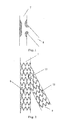
- Bifurcation lesion as indicated by the shadow areas in Fig. 1 is a common multiple-site artery stenosis wherein the vascular lesion site is located at the bifurcation between main vessel 7 and branch vessel 8.
- a stent for a bifurcated vessel with a wedge-shaped end is typically employed for the treatment of bifurcation lesions. As shown in Fig.
- the main-vessel stent is denoted by the reference sign 9
- the stent for a bifurcated vessel is denoted by the reference sign 12
- the wedge-shaped structure on the stent for a bifurcated vessel is denoted by the reference sign 13.
- the inventor After investigating the prior art of the field, the inventor has found that although the existing stent for a bifurcated vessel with a wedge structure is capable of providing excellent treatment to the bifurcation lesion, the slant of the wedge structure of the stent for a bifurcated vessel cannot be positioned properly. In other words, it is impossible to guarantee a proper fit between the slant of the wedge structure of the stent for a bifurcated vessel and the main-vessel stent. Thereby the slant section of the implanted stent may deviate from the main vessel, which is detrimental to therapeutic effect.
- a stent for a bifurcated vessel is provided in embodiments of the present application, wherein a first opaque point and a second opaque point are disposed on the stent body in order to solve the problem associated with the existing stent for a bifurcated vessel that it cannot be precisely positioned during implantation.
- said two first opaque markers are located at the other open end of the stent body.
- the distance between said two first opaque markers equals to the diameter of said stent body.
- said second opaque marker when the number of said second opaque marker is one, said second opaque marker is located at any one end of the long axis of the slant of the wedge structure; when the number of said second opaque marker is two, said second opaque markers are located at both ends of the long axis of the slant of the wedge structure.
- protruded tooth-like structures are provided around the slant of said wedge structure.
- the axial length of said wedge structure is 1-15mm.
- the angle between the slant of said wedge structure and the axial direction of said stent body is 5-85 degree.
- the diameter of said stent for a bifurcated vessel is 2.25mm-10.0mm.
- said stent for a bifurcated vessel is a coronary artery bifurcation stent.
- the diameter of said coronary artery bifurcation stent is 2.25mm-5.0mm.
- said stent body is made of a material with excellent biocompatibility and mechanical properties selected from stainless steel, cobalt-chromium alloy, nickel-based alloy, degradable magnesium alloy or polymeric materials.
- the examples of the present application provide a stent for a bifurcated vessel comprising a stent body having two open ends, wherein at least one of the open ends of the stent body is a wedge structure, the stent body is provided with two first opaque markers, and the connecting line between the two first opaque markers is parallel to the slant of the wedge structure, at least one second opaque marker is provided on the two ends of the long axis of the slant of the wedge structure.
- the operator firstly delivers the wedge structure of the stent for a bifurcated vessel precisely to the bifurcation site of the blood vessel by observing the second opaque marker under X-ray, and then the operator can adjust the stent for a bifurcated vessel by observing the two first opaque markers under X-ray to overlap the two first opaque markers.
- the operator can precisely position the wedge structure of the stent for a bifurcated vessel by observing the first opaque markers so that the slant of the wedge structure of the stent for a bifurcated vessel fits the slant at the blood vessel bifurcation site.
- the stent for a bifurcated vessel provided herein can avoid the problem associated with the existing stent for a bifurcated vessel that the wedge structure deviates from the main vessel during implantation.
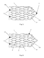
- Fig. 3 is the first schematic structural diagram showing the cross-section of a stent for a bifurcated vessel of the embodiment of the present application.
- Fig. 4 is the second schematic structural diagram showing the cross-section of a stent for a bifurcated vessel of the embodiment of the present application.
- the stent for a bifurcated vessel comprises a stent body 1 having two open ends, namely a first open end 101 and a second open end 102, in which the second open end 102 is a wedge-shaped structure.
- the angle between the slant of the wedge structure and the axial direction of the stent body 1 is preferably 45 degree, and the axial length of the wedge structure is within the range of 1-15mm.
- the stent body 1 is composed of multiple sets of mental loop 2 and connecting stems 3. Each set of mental loop 2 is formed by connecting multiple wavelike rods 4 together and the connecting stems 3 is positioned between the adjacent mental loops 2 to connect the adjacent mental loops 2.
- the stent for a bifurcated vessel is suitable for various parts of a human body, such as cerebral artery bifurcation stent, femoral artery bifurcation stent, coronary artery bifurcation stent and the like.
- the diameter of the stent for a bifurcated vessel is preferably 2.25mm-10.0mm.
- the stent for a bifurcated vessel is preferably a coronary artery bifurcation stent and the diameter of the coronary artery bifurcation stent is 2.25mm-5.0mm.
- the stent body 1 can also be made by weaving metal filaments or formed by etching tubular materials.
- the stent body 1 is made of a material with excellent biocompatibility and mechanical properties, such as stainless steel, cobalt-chromium alloy, nickel-based alloy, degradable magnesium alloy or polymeric materials etc.
- two second opaque markers 6 are provided on the second open end 102 of the stent 1, and the second opaque markers are positioned on the opposite ends of the long axis of the slant of the wedge structure.
- two first opaque markers 5 are provided on the stent 1, and the connecting line between the two first opaque markers 5 is parallel to the slant of the wedge structure.
- the two first opaque markers 5 are preferably located at the first open end 101, and preferably, the distance between the two first opaque markers 5 equals to the diameter of the stent body 1.
- the first opaque marker 5 and the second opaque marker 6 can be opaque metal sheet embedded on the wavelike rod 4 of the stent, or opaque film coated on the wavelike rod 4 of the stent, or opaque filament winded on the wavelike rod 4 of the stent.
- the number of the second opaque marker 6 can be one and the second opaque marker 6 is located at any one end of the long axis of the slant of the wedge structure.
- Fig. 5 which is a schematic structural diagram of another stent for a bifurcated vessel of the embodiment of the present application, one second opaque marker 6 is provided and located at the bottom of the wedge structure (the side close to the top end of the second open end 102 is defined as top).
- Fig. 6 which is a schematic structural diagram of a third stent for a bifurcated vessel of the embodiment of the present application, also shows that one second opaque marker 6 is provided and located at the top of the wedge structure.
- the second opaque marker 6 is provided on the two ends of the long axis of the slant of the wedge structure, the development thereof under X-ray will indicate the position of the wedge structure of the stent for a bifurcated vessel, no matter one or two second opaque markers 6 being disposed on the stent.
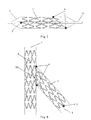
- Fig. 8 is a schematic diagram showing an operation of a stent for a bifurcated vessel of the embodiment of the present application.
- vascular stenosis occurs in both main vessel 7 and branch vessel 8
- a main-vessel stent is denoted by the reference sign 9.
- the implantation of the stent is performed in combination with the use of the balloon dilation catheter 10.
- Fig. 8 As shown in Fig.
- the stent for a bifurcated vessel is first compressed to be in tight contact with the balloon 11 of the balloon dilation catheter 10 before implantation; and then the balloon dilation catheter 10 is guided to the branch vessel 8 through the main vessel 7; the wedge structure of the stent body 1 is delivered precisely to the vascular bifurcation site by moving back and forth the balloon dilation catheter 10 based on the second opaque marker 6 under X-ray; and the stent for a bifurcated vessel is adjusted so that the wedge structure of the stent body 1 and the main-vessel stent 9 is jointed together based on the first opaque marker 5 under X-ray.
- the jointing procedure is described as follows: the operator observes whether the two first opaque points 5 overlap under X-ray.
- the operator turns the balloon dilation catheter 10 so that the two first opaque points 5 will overlap. Due to the fact that the connecting line between the two first opaque points 5 is parallel to the slant of the wedge structure, the projection of the slant of the wedge structure is shown as a line in the perspective of the operator when the two first opaque points 5 overlap. This means that the joint between the slant of the wedge structure and the main-vessel stent 9 is accomplished. When the jointing procedure is finished, the stent for a bifurcated vessel is then released and dilated to completely cover the vascular lesion site as shown in Fig. 8 . Then the implantation process is completed.
- Fig. 3 is a schematic structural diagram of the stent for a bifurcated vessel of the embodiments of the present application
- protruded tooth-like structures 14 are provided on the wedge structure of the second open end 102.
- the tooth-like structures 14 are arranged around the slant of the wedge structure and the extending direction thereof can be parallel to that of the stent body 1 or can extend outward.
- the tooth-like structures 14 on the wedge structure can be inserted into the main-vessel stent 9 or cover the opening of the main-vessel stent 9, so that the stent for a bifurcated vessel can more tightly contact the main-vessel stent 9.
- At least one open end of the stent body of the stent for a bifurcated vessel provided in the embodiments of the present application is a wedge structure.
- Two first opaque markers are provided on the stent body, and the connecting line between the two first opaque markers is parallel to the slant of the wedge structure.
- At least one second opaque marker is provided on the two ends of the long axis of the slant of the wedge structure.
- the operator adjusts the stent for a bifurcated vessel by observing the two first opaque markers under X-ray to overlap the two first opaque markers. Since the connecting line between the two first opaque markers is parallel to the slant of the wedge structure, the operator can precisely position the wedge structure of the stent for a bifurcated vessel by observing the first opaque markers so that the slant of the wedge structure of the stent for a bifurcated vessel matches the slant at the blood vessel bifurcation site.
- the stent for a bifurcated vessel provided herein can avoid the problem associated with the existing stent for a bifurcated vessel that the wedge structure deviates from the main vessel during implantation.
Landscapes
- Health & Medical Sciences (AREA)
- Engineering & Computer Science (AREA)
- Biomedical Technology (AREA)
- Cardiology (AREA)
- Oral & Maxillofacial Surgery (AREA)
- Transplantation (AREA)
- Heart & Thoracic Surgery (AREA)
- Vascular Medicine (AREA)
- Life Sciences & Earth Sciences (AREA)
- Animal Behavior & Ethology (AREA)
- General Health & Medical Sciences (AREA)
- Public Health (AREA)
- Veterinary Medicine (AREA)
- Physics & Mathematics (AREA)
- Optics & Photonics (AREA)
- Media Introduction/Drainage Providing Device (AREA)
- Prostheses (AREA)
Applications Claiming Priority (2)
| Application Number | Priority Date | Filing Date | Title |
|---|---|---|---|
| CN201010543016.9A CN102462563B (zh) | 2010-11-12 | 2010-11-12 | 一种分叉血管支架 |
| PCT/CN2011/078445 WO2012062144A1 (zh) | 2010-11-12 | 2011-08-16 | 一种分叉血管支架 |
Publications (2)
| Publication Number | Publication Date |
|---|---|
| EP2638882A1 true EP2638882A1 (de) | 2013-09-18 |
| EP2638882A4 EP2638882A4 (de) | 2016-01-20 |
Family
ID=46050382
Family Applications (1)
| Application Number | Title | Priority Date | Filing Date |
|---|---|---|---|
| EP11839759.5A Withdrawn EP2638882A4 (de) | 2010-11-12 | 2011-08-16 | Gegabelter blutgefäss-stent |
Country Status (4)
| Country | Link |
|---|---|
| US (1) | US20130304191A1 (de) |
| EP (1) | EP2638882A4 (de) |
| CN (1) | CN102462563B (de) |
| WO (1) | WO2012062144A1 (de) |
Cited By (2)
| Publication number | Priority date | Publication date | Assignee | Title |
|---|---|---|---|---|
| EP3740167A4 (de) * | 2018-01-16 | 2021-11-03 | Sintra Medical Llc | Stents mit erhöhter flexibilität |
| US12232990B2 (en) | 2019-07-16 | 2025-02-25 | Sintra Medical Llc | Stents with increased flexibility |
Families Citing this family (17)
| Publication number | Priority date | Publication date | Assignee | Title |
|---|---|---|---|---|
| CN103654923A (zh) * | 2012-09-19 | 2014-03-26 | 上海微创医疗器械(集团)有限公司 | 防止骨水泥渗漏的支架系统及其应用 |
| US9254208B2 (en) | 2013-03-14 | 2016-02-09 | Thomas Ischinger | Oblique stent |
| CN105188617B (zh) * | 2013-05-07 | 2017-03-08 | 株式会社钟化 | 支架、其制造方法及制造装置 |
| CN106333773B (zh) * | 2015-07-07 | 2018-05-08 | 先健科技(深圳)有限公司 | 血管支架 |
| CN106691647B (zh) * | 2015-07-20 | 2019-05-24 | 上海交通大学 | 一种生物可降解金属血管支架及其应用 |
| CN105457105B (zh) * | 2015-07-24 | 2018-08-31 | 中国科学院金属研究所 | 一种可显影镁合金血管支架 |
| US9937333B2 (en) | 2015-09-01 | 2018-04-10 | Thomas Ischinger | Balloon catheter for treatment of a vessel at a bifurcation |
| US11406517B2 (en) | 2017-11-17 | 2022-08-09 | Hangzhou Endonom Medtech Co. Ltd. | Vascular stent |
| CN109893308B (zh) * | 2017-12-06 | 2021-10-22 | 元心科技(深圳)有限公司 | 支架及其制备方法 |
| CN108553206A (zh) * | 2018-05-15 | 2018-09-21 | 中国医学科学院北京协和医院 | 血管支架及血管涂层支架 |
| CN111150433B (zh) * | 2018-11-08 | 2024-12-31 | 先健科技(深圳)有限公司 | 封堵器 |
| CN110448393B (zh) * | 2018-12-18 | 2021-04-13 | 深圳市先健畅通医疗有限公司 | 管腔支架 |
| CN112823766B (zh) * | 2019-11-21 | 2022-12-20 | 深圳市先健畅通医疗有限公司 | 双层管腔支架 |
| CN113967117A (zh) * | 2020-07-23 | 2022-01-25 | 赛诺医疗科学技术股份有限公司 | 可降解镁合金药物洗脱支架 |
| CN114569305A (zh) * | 2020-12-01 | 2022-06-03 | 浙江归创医疗器械有限公司 | 管状支架 |
| CN116059019B (zh) * | 2021-11-01 | 2025-08-05 | 先健科技(深圳)有限公司 | 管腔支架 |
| CN115381591B (zh) * | 2022-08-01 | 2023-07-25 | 上海玮琅医疗科技有限公司 | 一种直筒型上腔静脉支架 |
Family Cites Families (7)
| Publication number | Priority date | Publication date | Assignee | Title |
|---|---|---|---|---|
| US5893887A (en) * | 1997-10-14 | 1999-04-13 | Iowa-India Investments Company Limited | Stent for positioning at junction of bifurcated blood vessel and method of making |
| EP1164968A1 (de) * | 1999-03-30 | 2002-01-02 | Angiolink Corporation | Abgewinkelter vaskulärer stent |
| US6468301B1 (en) * | 2000-03-27 | 2002-10-22 | Aga Medical Corporation | Repositionable and recapturable vascular stent/graft |
| US7252679B2 (en) * | 2001-09-13 | 2007-08-07 | Cordis Corporation | Stent with angulated struts |
| FR2870716B1 (fr) * | 2004-05-27 | 2007-08-10 | Francis Besse | Stent endovasculaire et procede pour son obtention |
| CN200966659Y (zh) * | 2006-06-07 | 2007-10-31 | 北京乐普医疗器械有限公司 | 分叉血管楔型支架 |
| CN102068331B (zh) * | 2010-04-20 | 2013-08-07 | 上海微创医疗器械(集团)有限公司 | 一种分叉血管支架 |
-
2010
- 2010-11-12 CN CN201010543016.9A patent/CN102462563B/zh active Active
-
2011
- 2011-08-16 US US13/884,642 patent/US20130304191A1/en not_active Abandoned
- 2011-08-16 WO PCT/CN2011/078445 patent/WO2012062144A1/zh not_active Ceased
- 2011-08-16 EP EP11839759.5A patent/EP2638882A4/de not_active Withdrawn
Cited By (3)
| Publication number | Priority date | Publication date | Assignee | Title |
|---|---|---|---|---|
| EP3740167A4 (de) * | 2018-01-16 | 2021-11-03 | Sintra Medical Llc | Stents mit erhöhter flexibilität |
| US11389312B2 (en) | 2018-01-16 | 2022-07-19 | Sintra Medical Llc | Stents with increased flexibility |
| US12232990B2 (en) | 2019-07-16 | 2025-02-25 | Sintra Medical Llc | Stents with increased flexibility |
Also Published As
| Publication number | Publication date |
|---|---|
| EP2638882A4 (de) | 2016-01-20 |
| CN102462563A (zh) | 2012-05-23 |
| CN102462563B (zh) | 2015-11-11 |
| US20130304191A1 (en) | 2013-11-14 |
| WO2012062144A1 (zh) | 2012-05-18 |
Similar Documents
| Publication | Publication Date | Title |
|---|---|---|
| EP2638882A1 (de) | Gegabelter blutgefäss-stent | |
| US11013626B2 (en) | Endovascular delivery system with an improved radiopaque marker scheme | |
| CN109789009B (zh) | 用于将假体植入物联接到开窗体的系统、装置和方法 | |
| US11369466B2 (en) | Vascular prosthesis with moveable fenestration and method of use | |
| US8702780B2 (en) | Endovascular deployment device | |
| JP4783876B2 (ja) | ステントグラフト、ステントグラフトデリバリー(送入)システムおよびキット、およびステントグラフトを留置する方法 | |
| CN102014805B (zh) | 覆膜支架输送系统的双捕捉装置和覆膜支架捕捉法 | |
| CN102143723B (zh) | 用于治疗脑动脉瘤的薄膜植入物 | |
| JPH0759802A (ja) | 多カプセル管腔内移植装置 | |
| KR20060072137A (ko) | 스텐트 그래프트, 스텐트 그래프트 전달 시스템, 그리고스텐트 그래프트를 이식하기 위한 키트 및 방법 | |
| JP2005506130A (ja) | 管腔内デバイスを固定するためのシステム | |
| WO2019011274A1 (zh) | 植入物的输送系统 | |
| US20130173016A1 (en) | Ureteral stent | |
| Inoue et al. | Clinical application of transluminal endovascular graft placement for aortic aneurysms | |
| JP2004506479A (ja) | カスタム血管内装具の製造方法 | |
| US20110276080A1 (en) | Intravascular device, method for manufacturing same, and kits including same | |
| RU2460500C1 (ru) | Устройство имплантата для сосудов человека и животных | |
| CN108553206A (zh) | 血管支架及血管涂层支架 | |
| BR102013023069A2 (pt) | Stent ostial auto-expansível e método de aplicação | |
| AU2008223395B2 (en) | Endovascular deployment device |
Legal Events
| Date | Code | Title | Description |
|---|---|---|---|
| PUAI | Public reference made under article 153(3) epc to a published international application that has entered the european phase |
Free format text: ORIGINAL CODE: 0009012 |
|
| 17P | Request for examination filed |
Effective date: 20130510 |
|
| AK | Designated contracting states |
Kind code of ref document: A1 Designated state(s): AL AT BE BG CH CY CZ DE DK EE ES FI FR GB GR HR HU IE IS IT LI LT LU LV MC MK MT NL NO PL PT RO RS SE SI SK SM TR |
|
| DAX | Request for extension of the european patent (deleted) | ||
| RA4 | Supplementary search report drawn up and despatched (corrected) |
Effective date: 20151222 |
|
| RIC1 | Information provided on ipc code assigned before grant |
Ipc: A61F 2/915 20130101ALI20151216BHEP Ipc: A61F 2/856 20130101AFI20151216BHEP |
|
| STAA | Information on the status of an ep patent application or granted ep patent |
Free format text: STATUS: THE APPLICATION IS DEEMED TO BE WITHDRAWN |
|
| 18D | Application deemed to be withdrawn |
Effective date: 20160722 |