EP2639122A1 - Bremssteuervorrichtung für ein elektrofahrzeug - Google Patents
Bremssteuervorrichtung für ein elektrofahrzeug Download PDFInfo
- Publication number
- EP2639122A1 EP2639122A1 EP11840515.8A EP11840515A EP2639122A1 EP 2639122 A1 EP2639122 A1 EP 2639122A1 EP 11840515 A EP11840515 A EP 11840515A EP 2639122 A1 EP2639122 A1 EP 2639122A1
- Authority
- EP
- European Patent Office
- Prior art keywords
- brake
- motor
- target deceleration
- regenerative
- vehicle speed
- Prior art date
- Legal status (The legal status is an assumption and is not a legal conclusion. Google has not performed a legal analysis and makes no representation as to the accuracy of the status listed.)
- Granted
Links
- 230000001172 regenerating effect Effects 0.000 claims abstract description 126
- 238000005086 pumping Methods 0.000 claims abstract description 46
- 230000009467 reduction Effects 0.000 claims description 8
- 230000003247 decreasing effect Effects 0.000 claims description 5
- 239000012530 fluid Substances 0.000 abstract description 84
- 238000000034 method Methods 0.000 description 15
- 230000008569 process Effects 0.000 description 15
- 230000004044 response Effects 0.000 description 6
- 238000010586 diagram Methods 0.000 description 5
- 230000000694 effects Effects 0.000 description 5
- 230000007704 transition Effects 0.000 description 4
- 230000006399 behavior Effects 0.000 description 3
- 230000000052 comparative effect Effects 0.000 description 3
- 230000009849 deactivation Effects 0.000 description 3
- 239000007788 liquid Substances 0.000 description 3
- 230000007246 mechanism Effects 0.000 description 2
- 230000002035 prolonged effect Effects 0.000 description 2
- 230000004043 responsiveness Effects 0.000 description 2
- 230000001629 suppression Effects 0.000 description 2
- 229910017435 S2 In Inorganic materials 0.000 description 1
- 238000007792 addition Methods 0.000 description 1
- 230000005540 biological transmission Effects 0.000 description 1
- 230000002542 deteriorative effect Effects 0.000 description 1
- 239000000446 fuel Substances 0.000 description 1
- 230000002265 prevention Effects 0.000 description 1
- 230000008929 regeneration Effects 0.000 description 1
- 238000011069 regeneration method Methods 0.000 description 1
- 238000011144 upstream manufacturing Methods 0.000 description 1
Images



Classifications
-
- B—PERFORMING OPERATIONS; TRANSPORTING
- B60—VEHICLES IN GENERAL
- B60T—VEHICLE BRAKE CONTROL SYSTEMS OR PARTS THEREOF; BRAKE CONTROL SYSTEMS OR PARTS THEREOF, IN GENERAL; ARRANGEMENT OF BRAKING ELEMENTS ON VEHICLES IN GENERAL; PORTABLE DEVICES FOR PREVENTING UNWANTED MOVEMENT OF VEHICLES; VEHICLE MODIFICATIONS TO FACILITATE COOLING OF BRAKES
- B60T8/00—Arrangements for adjusting wheel-braking force to meet varying vehicular or ground-surface conditions, e.g. limiting or varying distribution of braking force
- B60T8/17—Using electrical or electronic regulation means to control braking
-
- B—PERFORMING OPERATIONS; TRANSPORTING
- B60—VEHICLES IN GENERAL
- B60T—VEHICLE BRAKE CONTROL SYSTEMS OR PARTS THEREOF; BRAKE CONTROL SYSTEMS OR PARTS THEREOF, IN GENERAL; ARRANGEMENT OF BRAKING ELEMENTS ON VEHICLES IN GENERAL; PORTABLE DEVICES FOR PREVENTING UNWANTED MOVEMENT OF VEHICLES; VEHICLE MODIFICATIONS TO FACILITATE COOLING OF BRAKES
- B60T13/00—Transmitting braking action from initiating means to ultimate brake actuator with power assistance or drive; Brake systems incorporating such transmitting means, e.g. air-pressure brake systems
- B60T13/10—Transmitting braking action from initiating means to ultimate brake actuator with power assistance or drive; Brake systems incorporating such transmitting means, e.g. air-pressure brake systems with fluid assistance, drive, or release
- B60T13/12—Transmitting braking action from initiating means to ultimate brake actuator with power assistance or drive; Brake systems incorporating such transmitting means, e.g. air-pressure brake systems with fluid assistance, drive, or release the fluid being liquid
- B60T13/16—Transmitting braking action from initiating means to ultimate brake actuator with power assistance or drive; Brake systems incorporating such transmitting means, e.g. air-pressure brake systems with fluid assistance, drive, or release the fluid being liquid using pumps directly, i.e. without interposition of accumulators or reservoirs
- B60T13/20—Transmitting braking action from initiating means to ultimate brake actuator with power assistance or drive; Brake systems incorporating such transmitting means, e.g. air-pressure brake systems with fluid assistance, drive, or release the fluid being liquid using pumps directly, i.e. without interposition of accumulators or reservoirs with control of pump driving means
-
- B—PERFORMING OPERATIONS; TRANSPORTING
- B60—VEHICLES IN GENERAL
- B60T—VEHICLE BRAKE CONTROL SYSTEMS OR PARTS THEREOF; BRAKE CONTROL SYSTEMS OR PARTS THEREOF, IN GENERAL; ARRANGEMENT OF BRAKING ELEMENTS ON VEHICLES IN GENERAL; PORTABLE DEVICES FOR PREVENTING UNWANTED MOVEMENT OF VEHICLES; VEHICLE MODIFICATIONS TO FACILITATE COOLING OF BRAKES
- B60T13/00—Transmitting braking action from initiating means to ultimate brake actuator with power assistance or drive; Brake systems incorporating such transmitting means, e.g. air-pressure brake systems
- B60T13/10—Transmitting braking action from initiating means to ultimate brake actuator with power assistance or drive; Brake systems incorporating such transmitting means, e.g. air-pressure brake systems with fluid assistance, drive, or release
- B60T13/58—Combined or convertible systems
- B60T13/585—Combined or convertible systems comprising friction brakes and retarders
- B60T13/586—Combined or convertible systems comprising friction brakes and retarders the retarders being of the electric type
-
- B—PERFORMING OPERATIONS; TRANSPORTING
- B60—VEHICLES IN GENERAL
- B60T—VEHICLE BRAKE CONTROL SYSTEMS OR PARTS THEREOF; BRAKE CONTROL SYSTEMS OR PARTS THEREOF, IN GENERAL; ARRANGEMENT OF BRAKING ELEMENTS ON VEHICLES IN GENERAL; PORTABLE DEVICES FOR PREVENTING UNWANTED MOVEMENT OF VEHICLES; VEHICLE MODIFICATIONS TO FACILITATE COOLING OF BRAKES
- B60T8/00—Arrangements for adjusting wheel-braking force to meet varying vehicular or ground-surface conditions, e.g. limiting or varying distribution of braking force
- B60T8/17—Using electrical or electronic regulation means to control braking
- B60T8/1755—Brake regulation specially adapted to control the stability of the vehicle, e.g. taking into account yaw rate or transverse acceleration in a curve
-
- B—PERFORMING OPERATIONS; TRANSPORTING
- B60—VEHICLES IN GENERAL
- B60T—VEHICLE BRAKE CONTROL SYSTEMS OR PARTS THEREOF; BRAKE CONTROL SYSTEMS OR PARTS THEREOF, IN GENERAL; ARRANGEMENT OF BRAKING ELEMENTS ON VEHICLES IN GENERAL; PORTABLE DEVICES FOR PREVENTING UNWANTED MOVEMENT OF VEHICLES; VEHICLE MODIFICATIONS TO FACILITATE COOLING OF BRAKES
- B60T8/00—Arrangements for adjusting wheel-braking force to meet varying vehicular or ground-surface conditions, e.g. limiting or varying distribution of braking force
- B60T8/32—Arrangements for adjusting wheel-braking force to meet varying vehicular or ground-surface conditions, e.g. limiting or varying distribution of braking force responsive to a speed condition, e.g. acceleration or deceleration
- B60T8/34—Arrangements for adjusting wheel-braking force to meet varying vehicular or ground-surface conditions, e.g. limiting or varying distribution of braking force responsive to a speed condition, e.g. acceleration or deceleration having a fluid pressure regulator responsive to a speed condition
- B60T8/40—Arrangements for adjusting wheel-braking force to meet varying vehicular or ground-surface conditions, e.g. limiting or varying distribution of braking force responsive to a speed condition, e.g. acceleration or deceleration having a fluid pressure regulator responsive to a speed condition comprising an additional fluid circuit including fluid pressurising means for modifying the pressure of the braking fluid, e.g. including wheel driven pumps for detecting a speed condition, or pumps which are controlled by means independent of the braking system
- B60T8/404—Control of the pump unit
- B60T8/4045—Control of the pump unit involving ON/OFF switching
-
- B—PERFORMING OPERATIONS; TRANSPORTING
- B60—VEHICLES IN GENERAL
- B60T—VEHICLE BRAKE CONTROL SYSTEMS OR PARTS THEREOF; BRAKE CONTROL SYSTEMS OR PARTS THEREOF, IN GENERAL; ARRANGEMENT OF BRAKING ELEMENTS ON VEHICLES IN GENERAL; PORTABLE DEVICES FOR PREVENTING UNWANTED MOVEMENT OF VEHICLES; VEHICLE MODIFICATIONS TO FACILITATE COOLING OF BRAKES
- B60T8/00—Arrangements for adjusting wheel-braking force to meet varying vehicular or ground-surface conditions, e.g. limiting or varying distribution of braking force
- B60T8/32—Arrangements for adjusting wheel-braking force to meet varying vehicular or ground-surface conditions, e.g. limiting or varying distribution of braking force responsive to a speed condition, e.g. acceleration or deceleration
- B60T8/34—Arrangements for adjusting wheel-braking force to meet varying vehicular or ground-surface conditions, e.g. limiting or varying distribution of braking force responsive to a speed condition, e.g. acceleration or deceleration having a fluid pressure regulator responsive to a speed condition
- B60T8/48—Arrangements for adjusting wheel-braking force to meet varying vehicular or ground-surface conditions, e.g. limiting or varying distribution of braking force responsive to a speed condition, e.g. acceleration or deceleration having a fluid pressure regulator responsive to a speed condition connecting the brake actuator to an alternative or additional source of fluid pressure, e.g. traction control systems
- B60T8/4809—Traction control, stability control, using both the wheel brakes and other automatic braking systems
- B60T8/4827—Traction control, stability control, using both the wheel brakes and other automatic braking systems in hydraulic brake systems
- B60T8/4863—Traction control, stability control, using both the wheel brakes and other automatic braking systems in hydraulic brake systems closed systems
- B60T8/4872—Traction control, stability control, using both the wheel brakes and other automatic braking systems in hydraulic brake systems closed systems pump-back systems
-
- B—PERFORMING OPERATIONS; TRANSPORTING
- B60—VEHICLES IN GENERAL
- B60W—CONJOINT CONTROL OF VEHICLE SUB-UNITS OF DIFFERENT TYPE OR DIFFERENT FUNCTION; CONTROL SYSTEMS SPECIALLY ADAPTED FOR HYBRID VEHICLES; ROAD VEHICLE DRIVE CONTROL SYSTEMS FOR PURPOSES NOT RELATED TO THE CONTROL OF A PARTICULAR SUB-UNIT
- B60W10/00—Conjoint control of vehicle sub-units of different type or different function
- B60W10/04—Conjoint control of vehicle sub-units of different type or different function including control of propulsion units
- B60W10/08—Conjoint control of vehicle sub-units of different type or different function including control of propulsion units including control of electric propulsion units, e.g. motors or generators
-
- B—PERFORMING OPERATIONS; TRANSPORTING
- B60—VEHICLES IN GENERAL
- B60W—CONJOINT CONTROL OF VEHICLE SUB-UNITS OF DIFFERENT TYPE OR DIFFERENT FUNCTION; CONTROL SYSTEMS SPECIALLY ADAPTED FOR HYBRID VEHICLES; ROAD VEHICLE DRIVE CONTROL SYSTEMS FOR PURPOSES NOT RELATED TO THE CONTROL OF A PARTICULAR SUB-UNIT
- B60W30/00—Purposes of road vehicle drive control systems not related to the control of a particular sub-unit, e.g. of systems using conjoint control of vehicle sub-units
- B60W30/18—Propelling the vehicle
- B60W30/18009—Propelling the vehicle related to particular drive situations
- B60W30/18109—Braking
- B60W30/18127—Regenerative braking
-
- B—PERFORMING OPERATIONS; TRANSPORTING
- B60—VEHICLES IN GENERAL
- B60T—VEHICLE BRAKE CONTROL SYSTEMS OR PARTS THEREOF; BRAKE CONTROL SYSTEMS OR PARTS THEREOF, IN GENERAL; ARRANGEMENT OF BRAKING ELEMENTS ON VEHICLES IN GENERAL; PORTABLE DEVICES FOR PREVENTING UNWANTED MOVEMENT OF VEHICLES; VEHICLE MODIFICATIONS TO FACILITATE COOLING OF BRAKES
- B60T2270/00—Further aspects of brake control systems not otherwise provided for
- B60T2270/60—Regenerative braking
- B60T2270/604—Merging friction therewith; Adjusting their repartition
Definitions
- the present invention relates to a brake control device for an electrically driven vehicle such as hybrid vehicle and the like with a regenerative corporative brake control in which a target deceleration is achieved by the sum of a base hydraulic pressure portion and a regenerative portion, and the shortage of the regenerative portion is supplemented or compensated for by an increased pressure in the base hydraulic pressure as an add-on pressure portion.
- a vehicle equipped with a conventional brake device in a state where operation of the pumping motor is stopped below a predetermined vehicle speed (approximately zero) and thus a pressure increase is prohibited, such a scene (such as on congested roads or when parking in) may be assumed in which a gentle or moderate braking is performed while travelling at an extremely low speed such as in a creeping movement after the deactivation of the motor.
- the present invention has been made by focusing on the problems described above, and has the object to provide a brake control device that may suppress the discontinuous brake feel and thus giving rise to easiness to handle to the driver when generating a brake force by restarting the pumping motor stopped.
- the brake control device for an electrically driven vehicle is provided with a master cylinder, a wheel cylinder, a brake hydraulic pressure actuator, a regenerative brake force control unit, regenerative cooperative brake control unit, motor stop control unit and motor restart control unit.
- the master cylinder generates a master cylinder pressure in accordance with an operation of brake.
- the wheel cylinder is disposed at each front and rear wheel and supplies a hydraulic pressure braking power to each wheel.
- the brake hydraulic pressure actuator is interposed between the master cylinder and wheel cylinder and is provided with a hydraulic pressure pump driven by a pumping motor and a differential valve for controlling the pressure difference between the wheel cylinder pressure and master cylinder pressure when the pumping motor is in operation.
- the regenerative brake force control unit is connected to an electric drive motor for travelling coupled to the drive wheel and controls the regenerative brake force that is generated by the electric drive motor.
- the regenerative cooperative brake control unit achieves the target deceleration at the braking operation by the sum of a base hydraulic pressure portion by the master cylinder pressure and a regenerative portion by the regenerative brake force, and further compensates for the shortage of the regenerative portion by an add-on pressure portion by the brake hydraulic pressure actuator.
- the motor stop control unit stops the pumping motor in operation when the vehicle speed falls below a first predetermined vehicle speed.
- the motor restart control unit sets the target deceleration value lower than the target deceleration of driver's request and restarts the pumping motor when the vehicle speed exceeds a second predetermined vehicle speed and brake is operated.
- the motor restart control unit sets the target deceleration value lower than the target deceleration value of driver's request and restarts the pumping motor.
- the regenerative cooperative braking control unit carries out control to achieve the set target deceleration value by the sum of base hydraulic pressure portion, regenerative portion and add-on pressure portion. For example, in such a scene in which, after deactivation of the pumping motor, when restarting the pumping motor in response to a gentle or slow braking operation while advancing at extremely low speed, the required hydraulic pressure is low and the actual hydraulic pressure generated by the add-on pressure portion may develop an overshoot temporarily.
- FIG. 1 shows a system configuration of a hybrid electric vehicle (example of electrically driven vehicle) of a front wheel drive type to which a brake control system according to the first embodiment of the present invention can be applied.
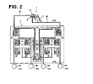
- FIG. 2 illustrates a VDC brake hydraulic pressure unit (example of brake fluid or hydraulic pressure actuatorl. Below is an explanation of the brake system configuration with references to FIGS. 1 , 2 .
- a brake deceleration generating mechanism of the brake control system includes, as shown in FIG. 1 , a brake fluid pressure generating unit 1, a VDC brake fluid pressure unit 2 (also called as a brake fluid pressure actuator), a stroke sensor 3, left front wheel cylinder 4FL, right front wheel cylinder 4FR, left rear wheel cylinder 4RL, right rear wheel cylinder, and an electric drive motor 5 for vehicle propulsion or travelling.
- the brake deceleration generation system in the first embodiment is a regenerative cooperative brake system that uses a vehicle dynamics control (VDC) system in a vehicle currently available and incorporated for a regenerative cooperation in the actual vehicle.
- VDC vehicle dynamics control
- Brake fluid pressure generating unit 1 generates a base brake fluid pressure in accordance with the driver's operation of a brake pedal. As shown in FIGS. 1 and 2 , the brake fluid pressure generating unit 1 includes a brake pedal 11, a vacuum booster 12, a master cylinder 13 and a reservoir tank 14. A brake pressure generated by the driver applying brake pedal 11 is amplified by vacuum booster 12, and a primary fluid pressure and a secondary fluid pressure will be generated by master cylinder 13.
- brake deceleration generated by master cylinder 13 should be set to be smaller than the target deceleration of driver demand.
- VDC brake fluid pressure unit 2 is interposed between brake fluid pressure generating unit 1 and wheel cylinders 4FL, 4FR, 4RL and 4RR associated with respective wheels.
- VDC brake fluid pressure unit 2 is a brake fluid pressure actuator and has fluid pressure pumps 22 driven by a VDC motor 21 (pumping motor), which is a dedicated electric motor.
- VDC brake fluid pressure unit 2 increases, maintains or reduces a pressure from master cylinder 13.
- VDC brake fluid pressure unit 2 and brake fluid pressure generating unit 1 are connected to each other via primary fluid conduit 61 and secondary fluid conduit 62.
- VDC brake fluid pressure unit 2 is connected to each wheel cylinder 4FL, 4FR, 4RL and 4RR through a left front wheel fluid conduit 63, a right front fluid conduit 64, a left rear wheel fluid conduit 65 and a right rear wheel fluid conduit 66, respectively. This way, when the driver applies brake pedal 11, a master cylinder pressure generated at brake fluid pressure generating unit 1 will further be raised by VDC fluid unit 2 and introduced into respective wheel cylinders 4FL, 4FR, 4RL, 4RR to exert a braking operation.
- VDC brake fluid generation unit 2 is detailed in FIG. 2 and has fluid pressure pumps 22 driven by VDC motor 21, reservoirs 23 and a master cylinder pressure sensor 24 for detecting an actual master cylinder pressure.
- Various solenoid valves are employed including a first master cylinder (M/C) cutoff solenoid valve 25 (e.g., a differential pressure valve), a second M/C cutoff solenoid valve 26 (e.g., a differential pressure valve), pressure holding solenoid valves 27 and pressure reduction solenoid valves 28.
- M/C cutoff solenoid valve 25 e.g., a differential pressure valve
- second M/C cutoff solenoid valve 26 e.g., a differential pressure valve
- pressure holding solenoid valves 27 e.g., a differential pressure valve
- pressure reduction solenoid valves 28 e.g., pressure reduction solenoid valves
- the stroke sensor 3 is provided to detect an operation amount or stroke by a driver. This stroke sensor 3 is added to the conventional VDC system to detect a target deceleration amount, i.e., a driver demanding deceleration level, for use in regenerative cooperative brake control.
- Respective wheel cylinders 4FL, 4FR, 4RL, 4RR are each provided at an associated brake disk for front or rear wheels, and each is supplied with a controlled hydraulic pressure.
- brake rotors or disks are clamped by brake pads to apply a friction force therebetween, which in turn results in a hydraulic brake force to wheels.
- Electric drive motor 5 is provided as a driving source for driving wheels (left and right front wheels 4FL, 4FR in this example) and functions as both a driving motor and a generator. Electric drive motor 5 transfers a driving force or torque to the driving wheels when driven by energy from the battery. Moreover, in a regenerative mode, the motor applies load to left and right front wheels and thus recovers kinetic energy through regenerative braking to feed the battery.
- the drive train of left and right front wheels (drive wheels) in which this electric drive motor 5 is interposed, is provided wit an engine 10 for drive source to travel and driving force is transmitted via transmission 11 to left and right wheels.
- the brake deceleration control system of brake control device of the first embodiment is provided, as shown in FIG. 1 , with a brake controller 7, motor controller 8 (regenerative brake force control unit), unified controller 9 and an engine controller 12.
- the brake controller 7 receives a fluid pressure command from unified controller 9 and pressure information from master cyllinder pressure sensor 24 of VDC brake fluid pressure unit 2. Then, in accordance with a predetermined control law, drive commands for the solenoid valves 25, 26, 27, and 28, and for VDC motor 21 of VDC brake fluid pressure unit 2 are output. In addition to the regenerative cooperative brake control, a VDC control, ABS control and TCS control are performed by this brake controller 7 in addition to the regenerative cooperation brake control.
- the motor controller 8 Is connected via an inverter 13 to the electric drive motor 5, which in turn is connected to the left and right front wheels as driving wheels.
- the regenerative brake control upon receipt of a regenerative braking command from the unified controller 9, the regenerative brake force generated by the electric drive motor 5 is controlled by the motor controller as the regenerative brake force control unit in accordance with input command.
- This motor controller 8 also functions to control the motor torque or motor rotation speed generated from the electric drive motor 5 depending on the running conditions or vehicle conditions during travelling.
- the unified controller 9 achieves the target deceleration by the sum of the base fluid pressure portion due to master cylinder pressure and regenerative portion from the regenerative brake force, the shortage of the regenerative portion is compensated for by the add-on portion by VDC fluid pressure unit.
- This unified controller 9 receives battery charge capacity information from the battery controller 91, the vehicle speed information from vehicle speed sensor 92, a brake operation information from the brake switch 93, brake pedal operation amount information from the stroke sensor 3, the master cylinder pressure information from the master cylinder pressure sensor 24, and the like.
- the vehicle speed sensor 92 such wheel speed detecting unit is used for detecting rotation speed extending up to extremely low vehicle speed region.
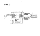
- FIG. 3 shows a regenerative cooperative brake control system of the first embodiment. Description is now made of the basic configuration of the regenerative cooperative brake control with reference to FIG. 3 . As shown in FIG. 3 , the regenerative cooperative brake control system of the first embodiment is provided with the brake controller 7, the motor controller 8, and a unified controller 9.
- the unified controller 9 has a target deceleration calculation unit 9a and a regenerative cooperative brake control unit 9b. Based on the pedal stroke sensor value from the stroke sensor 3, target deceleration calculation unit 9a calculates a target deceleration.
- the regenerative cooperative brake control unit 9b receives the target deceleration from the target deceleration calculation unit 9a, a MC pressure sensor value from the master cylinder pressure sensor 24, and a vehicle speed value from vehicle speed sensor 92, determines the base fluid pressure based on the MC sensor value, determines the regenerative portion and add-on pressure portion respectively, and performs a regenerative cooperative brake control calculation to achieve the target deceleration by the sum of the base fluid pressure portion, regenerative portion and the add-on pressure portion. Following this calculation result, the fluid pressure command corresponding to the add-on pressure portion will be output to brake controller 7 and the regenerative brake force command corresponding to the regenerative portion to motor controller 8, respectively.
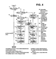
- FIG. 4 is a flow chart showing the configuration and flow of the regenerative cooperative brake control process executed by the unified controller in the brake control device of the first embodiment (regenerative cooperative brake control unit). Description of each step in FIG. 4 is now made below.
- step S1 determination is made whether or not vehicle speed V is less than a first predetermined value (first predetermined vehicle speed). If YES (vehicle speed V ⁇ first predetermined value), control proceeds to step S2, while if NO (vehicle speed V ⁇ first vehicle speed),control proceeds to step S3, respectively.
- first predetermined value first predetermined vehicle speed
- step S2 following the determination that vehicle speed V ⁇ first predetermined value (first predetermined vehicle speed) in step S1, VDC motor 21 is stopped to be driven, and process returns.
- step S3 after judging that vehicle speed value V ⁇ first predetermined value (first predetermined vehicle speed), the previous motor driven status of VDC motor 21 is determined. If ON (motor driven state), control proceeds to step S11, if NO (motor stopped state) control proceeds to step S4.
- step S4 following the determination of motor stopped state (OFF) in step S3, a determination is made whether or not vehicle speed V exceeds a second predetermined value (second predetermined vehicle speed). If YES, i.e., vehicle speed V >second predetermined value, control proceeds to step S6, if NO, i.e., vehicle speed V ⁇ second predetermined value, control proceeds to step S5.
- the "second predetermined value (second predetermined vehicle speed)" meets the relationship that the first predetermined value (first predetermined vehicle speed) is smaller than the second predetermined value (second predetermined vehicle speed). and is thus assumed to take a greater value than the first predetermined value (first predetermined vehicle speed). Having the two values different from each other this way is because of preventing the ON/OFF hunting of DC motor 21.
- step S5 following the judgment that vehicle speed V is equal to or smaller than the second predetermined value (second predetermined vehicle speed) or the judgment that the pedal stroke sensor value is equal to zero, the motor drive stopped state of VDC motor 21 will be continued and control returns.
- step S6 following the determination that vehicle speed V > second predetermined value (second predetermined vehicle speed), a braking request determination, i.e., whether or not the pedal stroke sensor value exceeds zero. If YES, i.e., pedal stroke sensor value is greater than zero, control proceeds to step S7, while if NO (pedal stroke sensor value is equal to zero), control proceeds to step S5.
- step S7 following the determination that pedal stroke sensor value is greater than zero in step S6, based on the brake pedal stroke and the first target deceleration calculation map (described in the framework of step S7), the target deceleration in accordance with brake pedal stroke is calculated and control proceeds to step S8.
- the regional or domain characteristic of the map characteristic between the stroke and a target deceleration below the first predetermined value of vehicle speed V is set to somewhat lower than the second target deceleration calculation map (as described within a block of step S12) that is used when vehicle speed V exceeds first predetermined value (first predetermined vehicle speed).
- the decrease width or range of reduction is defined by subtracting at least the overshoot of actual deceleration due to over-revolution of VDC motor 21 from the second target deceleration calculation map (described within the block of step S12) for obtaining the target deceleration of driver request.
- step S8 following the calculation of the target deceleration in step S7, the base liquid pressure portion is determined based on the MC pressure sensor value, the regenerative portion and add-on pressure portion are determined based on vehicle sensor value, and the regenerative cooperative brake control calculation to achieve the target deceleration by the sum of base liquid pressure portion, regenerative portion and add-on pressure portion, then control proceeds to step S9.
- step S9 following the regenerative cooperative brake control calculation in step S8, process determines a fluid pressure command value corresponding to the add-on pressure portion, outputs a fluid pressure command to obtain the fluid pressure command value to controller 7, and advances to step S10. At this time, when the regenerative portion is necessary, the process determines a regenerative brake force command value and outputs the regenerative brake force command to obtain the regenerative brake force command value to motor controller 8.
- step S10 following the determination of the fluid pressure command value in step S9, process restarts to motor drive of the VDC motor 21, generates the necessary deceleration by the sum of base fluid pressure portion, regenerative portion and add-on portion, and returns.
- step S12 following the determination in step 11 of pedal stroke sensor value being greater than zero, process calculates a target deceleration corresponding to the brake pedal stroke based on brake pedal stroke and the second target deceleration calculation map (i.e. the map described within the block of step S12, and proceeds to step S13.
- the second target deceleration calculation map sets a deceleration represented by the brake pedal stroke caused by the driver, i.e., the deceleration required by the driver as the target deceleration, and defines the target deceleration map characteristic to obtain this target deceleration.
- step S13 following the determination of the target deceleration in step S12, the process determines the base fluid pressure portion based on the MC pressure sensor value, determines the regenerative portion and add-on portion based on the vehicle speed sensor value, performs the regenerative cooperative brake control calculation to obtain the target deceleration by the sum of base fluid pressure portion, regenerative portion, and add-on portion, and finally proceeds to step S14.
- step S14 following the regenerative cooperative brake control calculation in step S13, control determines the fluid pressure command value corresponding to the add-on portion, outputs the fluid pressure command to obtain the fluid pressure command value to brake controller 7, and advances to step S15. At this time if the regenerative portion is required, control determines the regenerative brake force command value corresponding to the regenerative portion and outputs the regenerative brake command to motor controller 8 to obtain the regenerative brake force command value.
- step S15 following the determination of the fluid pressure command value in step S14, process drives VDC motor 21, generates the required deceleration by the sum of base fluid pressure portion, regenerative portion, and add-on portion, and returns.
- the regenerative cooperative brake control is intended, when such a scene arises in which the sum of base fluid pressure portion and regenerative portion does not fully fulfill the deceleration of driver request, to pressurize a fluid pressure of shortage by the VDC brake fluid pressure unit to achieve the deceleration the driver requires.
- description is now made based on FIGS. 5 to 8 .
- the deceleration of driver request is configured to be met by the base fluid pressure portion due to the vacuum or negative pressure booster.
- a gap of deceleration is provided by offsetting the deceleration of driver request so that the base fluid pressure portion would not reach the deceleration of driver request at braking operation.
- the gap of deceleration is representative of the shortage with respect to the deceleration of driver request.
- the deceleration of driver demand will be compensated for by the sum of vacuum booster (base fluid pressure portion) and regenerative brake (regenerative portion).
- the deceleration of driver demand is compensated for by the sum of vacuum booster (base fluid pressure portion), regenerative brake (regenerative portion) and VDC brake fluid pressure unit (add-on pressure portion).
- a cooperative regeneration brake system using the VDC may be configured inexpensively by merely changing the vacuum booster characteristic, VDC brake fluid pressure unit characteristic, and adding a stroke sensor with respect to existing conventional VDC.
- the safety function of the conventional VDC will thus be expanded (safety function + regenerative cooperative function).
- step S1 When vehicle speed V is equal to or greater than the first predetermined value (first predetermined vehicle speed), VDC motor 21 in motor driven state, and the brake operation condition in step S11 is satisfied, the flow of control is repeated In the flowchart shown in FIG. 4 that advances in the order; step S1 ⁇ step S3 ⁇ step S11 ⁇ step S12 ⁇ step S13 ⁇ step S14 ⁇ step S15 ⁇ return.
- step S12 the target deceleration is calculated based on the brake pedal stroke and the second target deceleration calculation map (described within the framework or block of step S12),corresponding to the brake pedal stroke.
- step S13 the base fluid pressure is determined based on MC pressure sensor value while the regenerative portion and add-on portion based on the vehicle speed sensor value, and a regenerative cooperative brake control calculation is performed by achieving the target deceleration by the total sum of base fluid pressure portion, regenerative portion, and add-on portion.
- step S14 the fluid pressure command value corresponding to the add-on pressure portion is determined, and the fluid pressure command to obtain the liquid pressure command value is output to the brake controller 7.
- the regenerative brake force command value corresponding to the amount of regenerative portion is determined, if there is the regenerative portion required, the regenerative brake force command to obtain the regenerative brake force command value is output to the motor controller 8.
- VDC motor 21 is driven, and the regenerative cooperative brake control for generating the necessary deceleration is carried out by the sum of base fluid pressure portion, regenerative portion and add-on pressure portion.
- step S1 When the vehicle speed V becomes less than the first predetermined value (first predetermined vehicle speed), the process proceeds to step S1 ⁇ step S2 In the flowchart of FIG 4 , and at step S2, VDC motor 21 is stopped to be driven., Once VDC motor 21 has become stopped driving, then unless the condition of vehicle speed in step S4 is satisfied (i.e., vehicle speed V >second predetermined value), in the flowchart of FIG 4 , the process repeats in line with step S1 ⁇ step S3 ⁇ step S4 ⁇ step S5 ⁇ return, and the VDC motor 21 is maintained to be stopped.
- the condition of vehicle speed in step S4 i.e., vehicle speed V >second predetermined value
- step S4 vehicle speed related condition in step S4
- vehicle speed V second predetermined value
- step S6 the flow in FIG. 4 , i.e. the flow of step S1 ⁇ step S3 ⁇ step S4 ⁇ step S6 ⁇ step S5 ⁇ return is repeated, where the VDC motor 21 is maintained in the stopped state.
- the VDC motor 21 operated at the same time as the brake operation is stopped when the vehicle speed V becomes less than a first predetermined value (first predetermined vehicle speed). Therefore, the operating frequency and prolonged operating time of the VDC motor 21 may be reduced while improving the durability and reliability of the VDC motor 21.
- step S4 i.e., vehicle speed V > second predetermined value
- step S6 brake operation condition in step S6
- step S7 the target deceleration is calculated corresponding to the brake pedal stroke based on the brake pedal stroke and the first target deceleration calculation map (described within the framework of the step S7),.
- step S8 the base fluid pressure is determined based on the MC pressure sensor value, the regenerative portion and add-on pressure portion are determined based on the vehicle speed sensor value, and the regenerative cooperative brake control calculation is conducted to attain the target deceleration by the sum of base fluid pressure portion, regenerative portion and add-on pressure portion.
- step S9 the fluid pressure command value corresponding to the add-on pressure is determined and the fluid pressure command to obtain the fluid pressure command value is output to the brake controller 7.
- step S10 the VDC motor 21 is restarted to drive, amd the regenerative cooperative brake control for generating the deceleration required by the sum of base fluid pressure portion, regenerative portion and add-on pressure portion.
- a comparative example is prepared in which only a single map is available for setting the target deceleration and even at a slow or gentle brake operation accompanied by motor restart, the brake control sets the normal target deceleration the driver requires.
- the operations are compared and described when the same scene of slow braking operation with motor restart is encountered by the vehicle with brake control device by the Comparative Example and the hybrid vehicle equipped with brake control device according to the first embodiment.
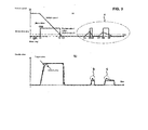
- braking operation is started to drive at time t1 and pumping motor is driven to operate.
- time t2 at which vehicle speed reaches a predetermined value
- driving of pumping motor is stopped or suspended, and immediately thereafter the vehicle stops at time t3.
- time t4 after the stop of driving of pumping motor, associated with the vehicle starting to travel at very low speed due to creeping torque or the like.
- the slow or gradual depression of brake is carried out at time t5 and pumping motor is allowed to operate.
- time t6 at which the vehicle speed reaches a predetermined value, the pumping motor will be stopped.
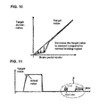
- the value of the target deceleration is set lower in advance than the value of the target deceleration which the driver requires as shown in FIG. 10 . Therefore, out of the base fluid pressure portion and regenerative portion, both are intended to share the target deceleration, the share or apportion of deceleration by the add-on pressure portion will be relatively reduced with the target rotation speed of VDC motor 21 decreased. Specifically, the base fluid pressure portion becomes substantially zero (see FIG.8 ).
- the regenerative portion can hardly be expected. That is, when decreasing the target deceleration, the deceleration sharing apportion of the fluid pressure due largely to the add-on pressure portion is reduced. Then, the add-on pressure portion will be obtained by control of the differential pressure valve (first M / C cut of solenoid valve 25, second M / C cut solenoid valve 26) and a pump-up boost by hydraulic or fluid pumps 22 and 22. Therefore, when the add-on pressure portion is lowered, the pump up width or range is in turn smaller, and the target rotation speed of the VDC motor 21 that drives hydraulic pump 22, 22 is made lower.
- the differential pressure valve first M / C cut of solenoid valve 25, second M / C cut solenoid valve 26
- the occurrence of deceleration overshoot in which the deceleration (actual value) sharply increases owing to the transitional over-speed of VDC motor 21 is prevented to occur. Consequently, the actual deceleration of the vehicle may be controlled to the target deceleration (target deceleration in FIG. 9(b) ) equivalent to that the driver requires. Therefore, when generating brake force by restarting VDC motor that has been stopped, the awkward brake feeling is suppressed and the braking is now easy to handle.
- the target deceleration is reduced to assume the value by subtracting from the target deceleration value which the driver requests at least a portion, i.e. a range of reduction corresponding to the overshoot of the actual deceleration caused by excessive rotation of at least the VDC motor 21. That is, in view of the portion or the range of reduction considering the occurrence of actual deceleration by overshooting of the motor rotation, the actual value of deceleration approximately matches the target value of the deceleration that should be originally intended at the time of restarting the motor. Therefore, while generating the vehicle deceleration that the driver requests, the discontinuous brake feel may be suppressed and the braking feeling will thus be improved.
- the target deceleration value is determined by the first target deceleration calculation map based on a brake pedal stroke as parameter, and the first target deceleration calculation map is further defined by decreasing by a range of reduction such that the target deceleration value is smaller in the first target deceleration calculation map at brake pedal being less than a predetermined value than a second target deceleration calculation map characteristic that is used at the vehicle speed being equal to or greater than the first predetermined value (first predetermined value). That is, the target deceleration is set at the characteristic that is reduced by a range of reduction at gentle braking operation. At a sharp braking, the target deceleration is set at the characteristic that represents the deceleration of driver request. Therefore, when restarting the motor, suppression of discontinuous brake feeling at gentle braking may be made compatible with ensuring the responsiveness of the demand for deceleration in response to sharp braking operation.
- the first embodiment is provided with:
- the motor restart control unit or process sets the target deceleration value by subtracting from the target deceleration value which the driver requests at vehicle speed V exceeding the first vehicle speed (first predetermined value) at least a portion corresponding to the overshoot of the actual deceleration caused by excessive rotation of the pumping motor (VDC motor 21) (step S7). Therefore, in addition to the above described effect (1), while generating the vehicle deceleration that the driver requests, the discontinuous brake feel may be suppressed and the braking feeling will thus be improved.
- the motor restart control unit or process sets the characteristics of the target deceleration in such a way that the target deceleration value is determined by a target deceleration calculation map (first target deceleration calculation map) based on a brake pedal operation amount (brake pedal stroke) as parameter, and the target deceleration calculation map (first target deceleration calculation map) is further defined by decreasing by a range of reduction such that the target deceleration value is smaller in the first target deceleration calculation map at brake pedal operation amount (brake pedal stroke) being less than a predetermined value than the characteristic of a target deceleration map (second target deceleration calculation map) that is used at the vehicle speed being equal to or greater than the first predetermined vehicle speed (first predetermined value). Therefore, in addition to the technical effects of (1) and (2) above, when restarting the pumping motor (VDC motor 21), suppression of discontinuous brake feeling at gentle braking may be made compatible with ensuring the responsiveness of the demand for de
- the second predetermined value (second predetermined vehicle speed) in step S4 is set greater e first predetermined value (first predetermined vehicle speed) so that an example of prevention of ON/OFF hunting of the VDC motor 21.
- first predetermined value first predetermined vehicle speed
- second predetermined vehicle speed second predetermined vehicle speed
- the target deceleration may also be calculated to generate the brake force by restarting the pumping motor in stopped state by an arithmetic process in which a predetermined correction amount will be subtracted from the target deceleration obtained from the normal target deceleration map when the conditions regarding vehicle speed and braking operation are established after the pumping motor has been stopped.
- VDC motor 21 is made ON at the same time of brake operation, and made OFF at vehicle stopped region.
- a motor ON/OFF control may be an alternatively in which the VDC motor may be made OFF in the region in which no add-on portion is required.
- a VDC brake hydraulic or fluid pressure actuator shown in FIG. 2 is used.
- a brake fluid pressure may suffice as long as provided with a fluid pressure pump driven by VDC motor, a differential pressure valve that controls the differential pressure between the wheel cylinder pressure and master cylinder pressure.
- the brake control device of the present invention In the first embodiment, an example of application of the brake control device of the present invention to a front-wheel drive hybrid vehicle is shown.
- the brake control device of the present invention will be able to be applied to an electric vehicle hybrid vehicle of rear-wheel drive, electric vehicle, fuel cell vehicle, etc. as long as a brake regenerative cooperative control of the hydraulic pressure with regenerative brake force is performed.
Landscapes
- Engineering & Computer Science (AREA)
- Transportation (AREA)
- Mechanical Engineering (AREA)
- Physics & Mathematics (AREA)
- Fluid Mechanics (AREA)
- Chemical & Material Sciences (AREA)
- Combustion & Propulsion (AREA)
- Automation & Control Theory (AREA)
- Regulating Braking Force (AREA)
- Electric Propulsion And Braking For Vehicles (AREA)
- Braking Systems And Boosters (AREA)
Applications Claiming Priority (2)
| Application Number | Priority Date | Filing Date | Title |
|---|---|---|---|
| JP2010249877 | 2010-11-08 | ||
| PCT/JP2011/072601 WO2012063572A1 (ja) | 2010-11-08 | 2011-09-30 | 電動車両のブレーキ制御装置 |
Publications (3)
| Publication Number | Publication Date |
|---|---|
| EP2639122A1 true EP2639122A1 (de) | 2013-09-18 |
| EP2639122A4 EP2639122A4 (de) | 2015-03-18 |
| EP2639122B1 EP2639122B1 (de) | 2017-11-08 |
Family
ID=46050726
Family Applications (1)
| Application Number | Title | Priority Date | Filing Date |
|---|---|---|---|
| EP11840515.8A Not-in-force EP2639122B1 (de) | 2010-11-08 | 2011-09-30 | Bremssteuervorrichtung für ein elektrofahrzeug |
Country Status (5)
| Country | Link |
|---|---|
| US (1) | US8998352B2 (de) |
| EP (1) | EP2639122B1 (de) |
| JP (1) | JP5447690B2 (de) |
| CN (1) | CN103201146B (de) |
| WO (1) | WO2012063572A1 (de) |
Families Citing this family (12)
| Publication number | Priority date | Publication date | Assignee | Title |
|---|---|---|---|---|
| CN103354790B (zh) * | 2011-02-09 | 2016-04-06 | 铃木株式会社 | 混合动力车辆的驱动控制设备及混合动力车辆 |
| JP5880533B2 (ja) * | 2013-12-13 | 2016-03-09 | トヨタ自動車株式会社 | 車両制御装置 |
| KR102286743B1 (ko) * | 2014-11-05 | 2021-08-09 | 현대모비스 주식회사 | 차량용 회생제동 시스템 제어 방법 |
| JP6279096B2 (ja) * | 2014-11-07 | 2018-02-14 | 本田技研工業株式会社 | 車両用ブレーキシステム及び車両用ブレーキ制御方法 |
| KR101704176B1 (ko) * | 2015-03-23 | 2017-02-07 | 현대자동차주식회사 | 하이브리드 차량의 제동 제어 방법 |
| US10696164B2 (en) | 2017-05-18 | 2020-06-30 | Ford Global Technologies, Llc | Optimizing regenerative braking efficiency in a hybrid vehicle |
| JP6626519B2 (ja) | 2018-01-26 | 2019-12-25 | 株式会社Subaru | 車両用制御装置 |
| KR102563595B1 (ko) * | 2018-10-05 | 2023-08-03 | 현대자동차주식회사 | 전동식 부스터 타입 제동 시스템의 킥-백 제어 시스템 및 방법 |
| US11498428B2 (en) | 2019-10-28 | 2022-11-15 | Caterpillar Inc. | Directional shift variable brake disengagement |
| JP7172950B2 (ja) * | 2019-10-31 | 2022-11-16 | トヨタ自動車株式会社 | 車両用ブレーキシステム |
| WO2022091879A1 (ja) * | 2020-10-26 | 2022-05-05 | 日立Astemo株式会社 | 車両用ブレーキ装置 |
| CN121133648B (zh) * | 2025-11-05 | 2026-04-14 | 上海谋行科技有限公司 | 一种用于电子机械制动系统的再生制动复合控制方法 |
Family Cites Families (10)
| Publication number | Priority date | Publication date | Assignee | Title |
|---|---|---|---|---|
| JP3565621B2 (ja) | 1995-06-30 | 2004-09-15 | 三菱自動車工業株式会社 | 車両の旋回制御装置 |
| JP2000280890A (ja) | 1999-03-30 | 2000-10-10 | Unisia Jecs Corp | ブレーキ装置 |
| JP4389407B2 (ja) * | 2001-05-11 | 2009-12-24 | トヨタ自動車株式会社 | 液圧源装置 |
| JP4296991B2 (ja) * | 2004-06-08 | 2009-07-15 | 株式会社アドヴィックス | 車両用ブレーキ装置 |
| JP4415379B2 (ja) | 2004-09-30 | 2010-02-17 | 株式会社アドヴィックス | 車両用ブレーキ装置 |
| US8366210B2 (en) * | 2006-04-03 | 2013-02-05 | Advics Co., Ltd. | Braking apparatus for vehicle |
| JP4623090B2 (ja) * | 2007-12-25 | 2011-02-02 | トヨタ自動車株式会社 | ブレーキ制御装置 |
| JP5107075B2 (ja) * | 2008-01-31 | 2012-12-26 | トヨタ自動車株式会社 | 制動装置 |
| JP5150410B2 (ja) * | 2008-08-25 | 2013-02-20 | 日立オートモティブシステムズ株式会社 | ブレーキ装置 |
| JP5691453B2 (ja) * | 2010-12-03 | 2015-04-01 | 日産自動車株式会社 | 電動車両のブレーキ制御装置 |
-
2011
- 2011-09-30 JP JP2012542847A patent/JP5447690B2/ja not_active Expired - Fee Related
- 2011-09-30 WO PCT/JP2011/072601 patent/WO2012063572A1/ja not_active Ceased
- 2011-09-30 EP EP11840515.8A patent/EP2639122B1/de not_active Not-in-force
- 2011-09-30 US US13/820,114 patent/US8998352B2/en not_active Expired - Fee Related
- 2011-09-30 CN CN201180053888.XA patent/CN103201146B/zh not_active Expired - Fee Related
Also Published As
| Publication number | Publication date |
|---|---|
| WO2012063572A1 (ja) | 2012-05-18 |
| EP2639122A4 (de) | 2015-03-18 |
| JP5447690B2 (ja) | 2014-03-19 |
| CN103201146A (zh) | 2013-07-10 |
| US8998352B2 (en) | 2015-04-07 |
| CN103201146B (zh) | 2015-07-15 |
| JPWO2012063572A1 (ja) | 2014-05-12 |
| US20130154344A1 (en) | 2013-06-20 |
| EP2639122B1 (de) | 2017-11-08 |
Similar Documents
| Publication | Publication Date | Title |
|---|---|---|
| EP2639122B1 (de) | Bremssteuervorrichtung für ein elektrofahrzeug | |
| CN103153723B (zh) | 车辆制动控制装置 | |
| JP6056340B2 (ja) | 制動制御装置 | |
| CN103153724B (zh) | 电动车辆的制动控制装置 | |
| JP5797542B2 (ja) | ブレーキ装置 | |
| JP2013177024A (ja) | 電動車両のブレーキ制御装置 | |
| JP5853573B2 (ja) | 制動力制御装置 | |
| JP2012030731A (ja) | 電動車両のブレーキ制御装置 | |
| KR102187631B1 (ko) | 차량의 제동 장치 및 제동 제어 방법 | |
| JP5966663B2 (ja) | 車両のブレーキ制御装置 | |
| JP2014080126A (ja) | 車両のブレーキ制御装置 | |
| JP5879974B2 (ja) | 車両のブレーキ制御装置 | |
| JP5567791B2 (ja) | 車両の制動力制御装置 | |
| JP5799741B2 (ja) | ブレーキ制御装置 | |
| JP5966662B2 (ja) | 車両のブレーキ制御装置 | |
| JP5872412B2 (ja) | ブレーキ制御装置 | |
| JP5765180B2 (ja) | ブレーキ制御装置 | |
| JP2024011638A (ja) | 車両の制動制御装置 |
Legal Events
| Date | Code | Title | Description |
|---|---|---|---|
| PUAI | Public reference made under article 153(3) epc to a published international application that has entered the european phase |
Free format text: ORIGINAL CODE: 0009012 |
|
| 17P | Request for examination filed |
Effective date: 20130227 |
|
| AK | Designated contracting states |
Kind code of ref document: A1 Designated state(s): AL AT BE BG CH CY CZ DE DK EE ES FI FR GB GR HR HU IE IS IT LI LT LU LV MC MK MT NL NO PL PT RO RS SE SI SK SM TR |
|
| DAX | Request for extension of the european patent (deleted) | ||
| A4 | Supplementary search report drawn up and despatched |
Effective date: 20150213 |
|
| RIC1 | Information provided on ipc code assigned before grant |
Ipc: B60T 8/17 20060101AFI20150209BHEP |
|
| GRAP | Despatch of communication of intention to grant a patent |
Free format text: ORIGINAL CODE: EPIDOSNIGR1 |
|
| INTG | Intention to grant announced |
Effective date: 20170619 |
|
| GRAS | Grant fee paid |
Free format text: ORIGINAL CODE: EPIDOSNIGR3 |
|
| GRAA | (expected) grant |
Free format text: ORIGINAL CODE: 0009210 |
|
| AK | Designated contracting states |
Kind code of ref document: B1 Designated state(s): AL AT BE BG CH CY CZ DE DK EE ES FI FR GB GR HR HU IE IS IT LI LT LU LV MC MK MT NL NO PL PT RO RS SE SI SK SM TR |
|
| REG | Reference to a national code |
Ref country code: GB Ref legal event code: FG4D |
|
| REG | Reference to a national code |
Ref country code: CH Ref legal event code: EP Ref country code: AT Ref legal event code: REF Ref document number: 943839 Country of ref document: AT Kind code of ref document: T Effective date: 20171115 |
|
| REG | Reference to a national code |
Ref country code: IE Ref legal event code: FG4D |
|
| REG | Reference to a national code |
Ref country code: DE Ref legal event code: R096 Ref document number: 602011043245 Country of ref document: DE |
|
| REG | Reference to a national code |
Ref country code: NL Ref legal event code: MP Effective date: 20171108 |
|
| REG | Reference to a national code |
Ref country code: LT Ref legal event code: MG4D |
|
| REG | Reference to a national code |
Ref country code: AT Ref legal event code: MK05 Ref document number: 943839 Country of ref document: AT Kind code of ref document: T Effective date: 20171108 |
|
| PG25 | Lapsed in a contracting state [announced via postgrant information from national office to epo] |
Ref country code: SE Free format text: LAPSE BECAUSE OF FAILURE TO SUBMIT A TRANSLATION OF THE DESCRIPTION OR TO PAY THE FEE WITHIN THE PRESCRIBED TIME-LIMIT Effective date: 20171108 Ref country code: NL Free format text: LAPSE BECAUSE OF FAILURE TO SUBMIT A TRANSLATION OF THE DESCRIPTION OR TO PAY THE FEE WITHIN THE PRESCRIBED TIME-LIMIT Effective date: 20171108 Ref country code: FI Free format text: LAPSE BECAUSE OF FAILURE TO SUBMIT A TRANSLATION OF THE DESCRIPTION OR TO PAY THE FEE WITHIN THE PRESCRIBED TIME-LIMIT Effective date: 20171108 Ref country code: LT Free format text: LAPSE BECAUSE OF FAILURE TO SUBMIT A TRANSLATION OF THE DESCRIPTION OR TO PAY THE FEE WITHIN THE PRESCRIBED TIME-LIMIT Effective date: 20171108 Ref country code: NO Free format text: LAPSE BECAUSE OF FAILURE TO SUBMIT A TRANSLATION OF THE DESCRIPTION OR TO PAY THE FEE WITHIN THE PRESCRIBED TIME-LIMIT Effective date: 20180208 Ref country code: ES Free format text: LAPSE BECAUSE OF FAILURE TO SUBMIT A TRANSLATION OF THE DESCRIPTION OR TO PAY THE FEE WITHIN THE PRESCRIBED TIME-LIMIT Effective date: 20171108 |
|
| PG25 | Lapsed in a contracting state [announced via postgrant information from national office to epo] |
Ref country code: AT Free format text: LAPSE BECAUSE OF FAILURE TO SUBMIT A TRANSLATION OF THE DESCRIPTION OR TO PAY THE FEE WITHIN THE PRESCRIBED TIME-LIMIT Effective date: 20171108 Ref country code: IS Free format text: LAPSE BECAUSE OF FAILURE TO SUBMIT A TRANSLATION OF THE DESCRIPTION OR TO PAY THE FEE WITHIN THE PRESCRIBED TIME-LIMIT Effective date: 20180308 Ref country code: HR Free format text: LAPSE BECAUSE OF FAILURE TO SUBMIT A TRANSLATION OF THE DESCRIPTION OR TO PAY THE FEE WITHIN THE PRESCRIBED TIME-LIMIT Effective date: 20171108 Ref country code: LV Free format text: LAPSE BECAUSE OF FAILURE TO SUBMIT A TRANSLATION OF THE DESCRIPTION OR TO PAY THE FEE WITHIN THE PRESCRIBED TIME-LIMIT Effective date: 20171108 Ref country code: RS Free format text: LAPSE BECAUSE OF FAILURE TO SUBMIT A TRANSLATION OF THE DESCRIPTION OR TO PAY THE FEE WITHIN THE PRESCRIBED TIME-LIMIT Effective date: 20171108 Ref country code: BG Free format text: LAPSE BECAUSE OF FAILURE TO SUBMIT A TRANSLATION OF THE DESCRIPTION OR TO PAY THE FEE WITHIN THE PRESCRIBED TIME-LIMIT Effective date: 20180208 Ref country code: GR Free format text: LAPSE BECAUSE OF FAILURE TO SUBMIT A TRANSLATION OF THE DESCRIPTION OR TO PAY THE FEE WITHIN THE PRESCRIBED TIME-LIMIT Effective date: 20180209 |
|
| PG25 | Lapsed in a contracting state [announced via postgrant information from national office to epo] |
Ref country code: SK Free format text: LAPSE BECAUSE OF FAILURE TO SUBMIT A TRANSLATION OF THE DESCRIPTION OR TO PAY THE FEE WITHIN THE PRESCRIBED TIME-LIMIT Effective date: 20171108 Ref country code: CZ Free format text: LAPSE BECAUSE OF FAILURE TO SUBMIT A TRANSLATION OF THE DESCRIPTION OR TO PAY THE FEE WITHIN THE PRESCRIBED TIME-LIMIT Effective date: 20171108 Ref country code: EE Free format text: LAPSE BECAUSE OF FAILURE TO SUBMIT A TRANSLATION OF THE DESCRIPTION OR TO PAY THE FEE WITHIN THE PRESCRIBED TIME-LIMIT Effective date: 20171108 Ref country code: CY Free format text: LAPSE BECAUSE OF FAILURE TO SUBMIT A TRANSLATION OF THE DESCRIPTION OR TO PAY THE FEE WITHIN THE PRESCRIBED TIME-LIMIT Effective date: 20171108 Ref country code: DK Free format text: LAPSE BECAUSE OF FAILURE TO SUBMIT A TRANSLATION OF THE DESCRIPTION OR TO PAY THE FEE WITHIN THE PRESCRIBED TIME-LIMIT Effective date: 20171108 |
|
| REG | Reference to a national code |
Ref country code: DE Ref legal event code: R097 Ref document number: 602011043245 Country of ref document: DE |
|
| REG | Reference to a national code |
Ref country code: FR Ref legal event code: PLFP Year of fee payment: 8 |
|
| PG25 | Lapsed in a contracting state [announced via postgrant information from national office to epo] |
Ref country code: RO Free format text: LAPSE BECAUSE OF FAILURE TO SUBMIT A TRANSLATION OF THE DESCRIPTION OR TO PAY THE FEE WITHIN THE PRESCRIBED TIME-LIMIT Effective date: 20171108 Ref country code: IT Free format text: LAPSE BECAUSE OF FAILURE TO SUBMIT A TRANSLATION OF THE DESCRIPTION OR TO PAY THE FEE WITHIN THE PRESCRIBED TIME-LIMIT Effective date: 20171108 Ref country code: SM Free format text: LAPSE BECAUSE OF FAILURE TO SUBMIT A TRANSLATION OF THE DESCRIPTION OR TO PAY THE FEE WITHIN THE PRESCRIBED TIME-LIMIT Effective date: 20171108 Ref country code: PL Free format text: LAPSE BECAUSE OF FAILURE TO SUBMIT A TRANSLATION OF THE DESCRIPTION OR TO PAY THE FEE WITHIN THE PRESCRIBED TIME-LIMIT Effective date: 20171108 |
|
| PLBE | No opposition filed within time limit |
Free format text: ORIGINAL CODE: 0009261 |
|
| STAA | Information on the status of an ep patent application or granted ep patent |
Free format text: STATUS: NO OPPOSITION FILED WITHIN TIME LIMIT |
|
| 26N | No opposition filed |
Effective date: 20180809 |
|
| PG25 | Lapsed in a contracting state [announced via postgrant information from national office to epo] |
Ref country code: SI Free format text: LAPSE BECAUSE OF FAILURE TO SUBMIT A TRANSLATION OF THE DESCRIPTION OR TO PAY THE FEE WITHIN THE PRESCRIBED TIME-LIMIT Effective date: 20171108 |
|
| PG25 | Lapsed in a contracting state [announced via postgrant information from national office to epo] |
Ref country code: MC Free format text: LAPSE BECAUSE OF FAILURE TO SUBMIT A TRANSLATION OF THE DESCRIPTION OR TO PAY THE FEE WITHIN THE PRESCRIBED TIME-LIMIT Effective date: 20171108 |
|
| REG | Reference to a national code |
Ref country code: CH Ref legal event code: PL |
|
| REG | Reference to a national code |
Ref country code: BE Ref legal event code: MM Effective date: 20180930 |
|
| REG | Reference to a national code |
Ref country code: IE Ref legal event code: MM4A |
|
| PG25 | Lapsed in a contracting state [announced via postgrant information from national office to epo] |
Ref country code: LU Free format text: LAPSE BECAUSE OF NON-PAYMENT OF DUE FEES Effective date: 20180930 |
|
| PG25 | Lapsed in a contracting state [announced via postgrant information from national office to epo] |
Ref country code: IE Free format text: LAPSE BECAUSE OF NON-PAYMENT OF DUE FEES Effective date: 20180930 |
|
| PG25 | Lapsed in a contracting state [announced via postgrant information from national office to epo] |
Ref country code: BE Free format text: LAPSE BECAUSE OF NON-PAYMENT OF DUE FEES Effective date: 20180930 Ref country code: CH Free format text: LAPSE BECAUSE OF NON-PAYMENT OF DUE FEES Effective date: 20180930 Ref country code: LI Free format text: LAPSE BECAUSE OF NON-PAYMENT OF DUE FEES Effective date: 20180930 |
|
| PG25 | Lapsed in a contracting state [announced via postgrant information from national office to epo] |
Ref country code: MT Free format text: LAPSE BECAUSE OF NON-PAYMENT OF DUE FEES Effective date: 20180930 |
|
| PG25 | Lapsed in a contracting state [announced via postgrant information from national office to epo] |
Ref country code: TR Free format text: LAPSE BECAUSE OF FAILURE TO SUBMIT A TRANSLATION OF THE DESCRIPTION OR TO PAY THE FEE WITHIN THE PRESCRIBED TIME-LIMIT Effective date: 20171108 |
|
| PG25 | Lapsed in a contracting state [announced via postgrant information from national office to epo] |
Ref country code: HU Free format text: LAPSE BECAUSE OF FAILURE TO SUBMIT A TRANSLATION OF THE DESCRIPTION OR TO PAY THE FEE WITHIN THE PRESCRIBED TIME-LIMIT; INVALID AB INITIO Effective date: 20110930 Ref country code: PT Free format text: LAPSE BECAUSE OF FAILURE TO SUBMIT A TRANSLATION OF THE DESCRIPTION OR TO PAY THE FEE WITHIN THE PRESCRIBED TIME-LIMIT Effective date: 20171108 |
|
| PG25 | Lapsed in a contracting state [announced via postgrant information from national office to epo] |
Ref country code: MK Free format text: LAPSE BECAUSE OF NON-PAYMENT OF DUE FEES Effective date: 20171108 |
|
| PG25 | Lapsed in a contracting state [announced via postgrant information from national office to epo] |
Ref country code: AL Free format text: LAPSE BECAUSE OF FAILURE TO SUBMIT A TRANSLATION OF THE DESCRIPTION OR TO PAY THE FEE WITHIN THE PRESCRIBED TIME-LIMIT Effective date: 20171108 |
|
| PGFP | Annual fee paid to national office [announced via postgrant information from national office to epo] |
Ref country code: FR Payment date: 20210812 Year of fee payment: 11 |
|
| PGFP | Annual fee paid to national office [announced via postgrant information from national office to epo] |
Ref country code: GB Payment date: 20210825 Year of fee payment: 11 Ref country code: DE Payment date: 20210818 Year of fee payment: 11 |
|
| REG | Reference to a national code |
Ref country code: DE Ref legal event code: R119 Ref document number: 602011043245 Country of ref document: DE |
|
| GBPC | Gb: european patent ceased through non-payment of renewal fee |
Effective date: 20220930 |
|
| PG25 | Lapsed in a contracting state [announced via postgrant information from national office to epo] |
Ref country code: FR Free format text: LAPSE BECAUSE OF NON-PAYMENT OF DUE FEES Effective date: 20220930 Ref country code: DE Free format text: LAPSE BECAUSE OF NON-PAYMENT OF DUE FEES Effective date: 20230401 |
|
| PG25 | Lapsed in a contracting state [announced via postgrant information from national office to epo] |
Ref country code: GB Free format text: LAPSE BECAUSE OF NON-PAYMENT OF DUE FEES Effective date: 20220930 |