EP2639374A2 - Fixation de plaques d'isolation - Google Patents
Fixation de plaques d'isolation Download PDFInfo
- Publication number
- EP2639374A2 EP2639374A2 EP20130001244 EP13001244A EP2639374A2 EP 2639374 A2 EP2639374 A2 EP 2639374A2 EP 20130001244 EP20130001244 EP 20130001244 EP 13001244 A EP13001244 A EP 13001244A EP 2639374 A2 EP2639374 A2 EP 2639374A2
- Authority
- EP
- European Patent Office
- Prior art keywords
- setting
- insulation
- fastening element
- dowel
- insulating
- Prior art date
- Legal status (The legal status is an assumption and is not a legal conclusion. Google has not performed a legal analysis and makes no representation as to the accuracy of the status listed.)
- Granted
Links
Images


Classifications
-
- E—FIXED CONSTRUCTIONS
- E04—BUILDING
- E04B—GENERAL BUILDING CONSTRUCTIONS; WALLS, e.g. PARTITIONS; ROOFS; FLOORS; CEILINGS; INSULATION OR OTHER PROTECTION OF BUILDINGS
- E04B1/00—Constructions in general; Structures which are not restricted either to walls, e.g. partitions, or floors or ceilings or roofs
- E04B1/62—Insulation or other protection; Elements or use of specified material therefor
- E04B1/74—Heat, sound or noise insulation, absorption, or reflection; Other building methods affording favourable thermal or acoustical conditions, e.g. accumulating of heat within walls
- E04B1/76—Heat, sound or noise insulation, absorption, or reflection; Other building methods affording favourable thermal or acoustical conditions, e.g. accumulating of heat within walls specifically with respect to heat only
- E04B1/762—Exterior insulation of exterior walls
- E04B1/7629—Details of the mechanical connection of the insulation to the wall
-
- B—PERFORMING OPERATIONS; TRANSPORTING
- B23—MACHINE TOOLS; METAL-WORKING NOT OTHERWISE PROVIDED FOR
- B23B—TURNING; BORING
- B23B51/00—Tools for drilling machines
- B23B51/08—Drills combined with tool parts or tools for performing additional working
-
- E—FIXED CONSTRUCTIONS
- E04—BUILDING
- E04B—GENERAL BUILDING CONSTRUCTIONS; WALLS, e.g. PARTITIONS; ROOFS; FLOORS; CEILINGS; INSULATION OR OTHER PROTECTION OF BUILDINGS
- E04B1/00—Constructions in general; Structures which are not restricted either to walls, e.g. partitions, or floors or ceilings or roofs
- E04B1/62—Insulation or other protection; Elements or use of specified material therefor
- E04B1/74—Heat, sound or noise insulation, absorption, or reflection; Other building methods affording favourable thermal or acoustical conditions, e.g. accumulating of heat within walls
- E04B1/76—Heat, sound or noise insulation, absorption, or reflection; Other building methods affording favourable thermal or acoustical conditions, e.g. accumulating of heat within walls specifically with respect to heat only
- E04B1/762—Exterior insulation of exterior walls
- E04B1/7629—Details of the mechanical connection of the insulation to the wall
- E04B1/7633—Dowels with enlarged insulation retaining head
Definitions
- the present invention relates to a method for fixing insulation boards according to the preamble of claim 1, a system for fixing insulation boards or heat insulation according to the preamble of claim 13, a use of a fastener for fixing an insulation board according to the preamble of claim 14 and a setting tool for setting fasteners for fixing insulation boards.
- the present invention is generally concerned with the attachment of insulation panels to a structure.
- the insulation boards are in particular so-called insulation boards or thermal insulation boards. However, it may also be other facade panels o. The like. Act.
- the insulation boards are usually made of a relatively soft or not highly resilient insulation material, such as expanded polystyrene o. The like., Made. Accordingly, a secure attachment is important.
- the fixing of the insulating panels takes place on a building, in particular on a house or other building, on a facade, wall or ceiling.
- the attachment can preferably also be done on a different substructure.
- structure is therefore preferably to be understood in a correspondingly broad sense.
- the insulation boards are glued to the building and additionally secured with dowels.
- the attached insulation boards are then usually plastered. It is important, inter alia, that a good insulation, in particular thermal insulation, is achieved, particularly preferably no thermal bridges are formed, that dowel plate o. The like. Do not stand out from the outside and that a simple construction site appropriate mounting or mounting is possible.
- the DE 195 36 171 A1 provides dowels with dowel plates on the insulation board surface. This is disadvantageous in particular with regard to dowel markings.
- From the EP 0 086 452 A2 It is known to produce a recess in the insulating board for receiving a dowel plate simultaneously with the drilling of a borehole for a dowel in an insulating board.
- a countersunk drill which comprises a milling head and a disk-shaped stop, during drilling of the borehole in the same operation, a recess corresponding to the diameter of the anchor plate is milled into the insulating board.
- the dowel is then inserted into the recess with the anchor plate, wherein the recess is filled by an already applied to the dowel plate cover.
- the problem here is especially the milling dust and a flush closing of the insulation boards.
- the EP 1 318 250 A2 provides that Dübelteller be pulled starting from the outside of the insulation boards by driving a spreader into a dowel in the insulation and dowelled through the insulation boards through the building.
- the depth of insertion of the anchor plate depends on the driving of the expansion element.
- the DE 10 2006 006 164 A1 discloses a dowel for fastening of the plates, wherein the dowel has a dowel plate and a subsequent dowel sleeve and a particular designed as a screw fastener.
- the dowel plate is curved and plate underside sharp-edged with a blade-like plate lower edge formed on the outer circumference.
- a plug for engaging a Einschraubtechnikmaschines is arranged in the plate.
- the plug is non-rotatably coupled to the retaining plate and the screw.
- the anchor plate is sunk in the insulation board, wherein the depth of insertion of the anchor plate depends on the Einschraubmother the screw. Subsequently, the recess is closed by a Dämmstoffrondelle.
- the DE 10 2007 046 323 B3 discloses a similar dowel for fixing insulation boards.
- the dowel has a dowel plate with bottom milling devices.
- the anchor plate is provided with openings through which milled insulation or milling dust can pass.
- the dowel further has a subsequent to the dowel plate dowel sleeve for receiving a spreader.
- the expansion element is designed in particular as a screw and rotatably coupled to the anchor plate. Accordingly, when screwing the anchor plate is rotated and milled into the insulation board and thereby sunk.
- the milled insulating material is collected in a collecting device which is designed as a cap which receives the dowel plate, so that a circumferential cutting edge of the collecting device protrudes along the edge of the fastening element in the screwing direction and thereby facilitates penetration into the insulating board.
- the catcher remains in the insulation board after setting the anchor.
- the collecting device may have on its upper side a layer of the insulating material to improve the insulation and / or to facilitate uniform coverage, in particular by a plaster layer.
- the screwing-in tool is pulled out, wherein the catching device can have an opening for the screw-in device which closes by flexible lamellae.
- a disadvantage is the complex structure and the dependence of the installation depth of the anchor plate of the screw-in length of the screw.
- the DE 10 2006 060 538 A1 discloses a dowel for fixing insulation boards.
- the dowel has a dowel sleeve, a dowel plate and a rotatably coupled to the dowel plate expansion element, in particular in the form of a screw on.
- the anchor plate is provided on the insulating board side with a hollow cylindrical stop element and radially extending stiffening beads. When screwing in the expansion element of the anchor plate is rotated and sunk into the insulation board. Disadvantages are the relatively expensive Structure and the dependence of the penetration depth of the anchor plate of the Einschraubplic of the expansion element.
- the present invention has for its object to provide a method for fixing insulation boards, a system for fixing insulation boards, a fastener or its use for fixing insulation boards and a setting tool for setting fasteners for fixing insulation boards, with a simpler and less expensive Structure, use of standard dowels, a decoupling of the setting depth of a fastener of the screw-in length and / or a simple or secure attachment is or will be possible and / or wherein a marking of fasteners and / or unwanted thermal bridges are avoided or at least minimized.
- One aspect of the present invention is that for attaching insulation boards to a building initially plate-like fasteners in the insulation boards under rotation, ie in particular milling or crushing of insulation, introduced and thereby set in a desired depth of set, creating corresponding depressions in the Insulating boards are produced. Only then are the fasteners pegged to the structure, in particular the fact that dowels are inserted or inserted through the already introduced or set fasteners into an associated hole in the associated structure and spread by means of a spreading element. Subsequently, the fasteners are preferably sealed by plugs of insulating material flush with the outer surface of the associated insulation board.
- the fasteners may have a setting depth that is greater than the usually only about 2.5 cm amount of screwing length of dowel screws or Immersion depth of dowels in the structure is.
- the decoupling of the setting of the fasteners and the subsequent anchoring to the structure leads to greater flexibility.
- the use of standard dowels is possible. Consequently, a very simple and inexpensive construction is made possible.
- the storage is simplified. In particular, smaller packing volumes are made possible.
- a deeper arrangement of the fasteners leads to lower thermal bridges or better coverage and correspondingly better thermal insulation. Furthermore, this allows the use of shorter dowels.
- Another aspect of the present invention is that the setting depth of the fasteners is greater than the engagement length of the screws in the structure. This is conducive to good coverage or prevention of thermal bridges. Furthermore, this allows a simple structure.
- a proposed fastener or a proposed use is characterized in particular by the fact that it preferably has a integrally molded projection which surrounds an opening and forms an insertion bevel to facilitate the introduction of the fastener in the insulation material of the insulation board. This facilitates in particular the assembly.
- the fastening element preferably has an engagement portion for a setting tool for rotating the fastening element and a receptacle for abutment of a dowel.
- the receptacle is hollow, so that an associated dowel from the side facing away from the insulating plate of the fastener ago in the fastener insertable or insertable and can be inserted therethrough into an associated building.
- a proposed setting tool characterized by a protruding head with an engagement portion for rotationally fixed coupling with a fastener and by a coaxially arranged, circumferential cutting edge, wherein between the cutting edge and the head an annular receiving area for the Fastening element is formed.
- the proposed setting tool is characterized by the fact that its head is designed as a drill or designed to receive a drill. This allows a very simple installation, especially since a separate drilling can be omitted before setting the fasteners.
- plate-like fasteners are rotationally inserted into the insulation boards and then dowelled with the building.
- insulation is crushed or milled, the break-through fasteners and a protruding edge when setting the fasteners leakage of loose insulation, milling dust o. The like. Avoid. This allows a simple and / or dust-free installation or facilitates.
- the present invention particularly relates to an insulation system for insulating a structure, in particular a house o. The like., Wherein insulation panels are fastened by means of fastening elements to the building or are. Particularly preferred are or are fasteners that are connected by dowel joints with the building or dowelled at this. If necessary, the proposed insulation system also includes the building itself.
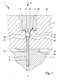
- FIG. 1 shows in a very schematic, not to scale section a preferred embodiment of a proposed insulation system or system 1 for fixing insulation boards 2 to a building 3. It is shown in FIG Fig. 1 a section or part of the system 1 or an insulating panel 2 with a fastening element 4 or in the region of a fastening element 4, which is dowelled to the structure 3.
- an insulating panel 2 and each insulation board 2 are assigned a plurality of fasteners 4, which are dowelled to the structure 3.
- the insulation board 2 is used in particular for thermal insulation or thermal insulation.
- the insulating board 2 is made of a corresponding insulating material, in particular, the insulating board 2 consists essentially or exclusively of this insulating material.
- a foamed insulation material such as expanded polystyrene, o. The like. Used.
- the insulation board 2 is preferably formed at least substantially square or rectangular. However, the insulation board 2 may in principle also have any other shape.
- the insulation board 2 usually has a thickness of several cm, for example, from 6 to 30 cm, usually about 10 to 16 cm on.
- the insulation board 2 is fixed with a flat side of the structure 3. This flat side is referred to here as construction site 2A.
- the insulation board 2 can be attached with their building side 2A directly to the building 3 and its surface 3A. However, between the structure 3 and the insulation board 2 - at least in regions, but possibly also over the entire surface - a cavity or a layer 3B, such as an intermediate layer or connecting layer, particularly preferably for compensating for unevenness and / or for bonding or gluing, as in Fig. 1 indicated, be provided. Particularly preferably, the insulation board 2 with the building 3 or its surface 3A bonded or otherwise connected, in particular material-locking, connected.
- the surface 3A of the structure 3 may in particular be formed by a plaster, masonry or the like.
- the surface 3A can form or represent a facade of the structure 3.
- Fig. 1 shows the system 1 and the insulation board 2 in a state attached to the structure 3, ie in a finished state.
- the fastening element 4 is introduced into the insulation board 2 and dowelled by means of a dowel 5 to the building 4.
- the dowel 5 is spread in this state by an inserted expansion element, in particular a screw 6, in the structure 3, the screw 6 is completely screwed in this state in the dowel 5.
- an other expansion element can be used, for example, an impact element in a knock-in anchor. The other comments apply accordingly.
- the fastening element 4 is preferably at least substantially plate-like or at least substantially substantially flat.
- the fastening element 4 is in particular substantially disc-shaped or circular-disk-like.
- the fastening element 4 has a portion 4A, which is formed at least substantially flat, disc-shaped, plate-like and / or ring-like and is therefore referred to as a plate portion.
- the fastening element 4 or the plate section 4A has a central opening 4B, which is preferably surrounded or formed by a projection 4C projecting in the direction of insertion E or radially.
- the fastening element 4 preferably has the opening 4B in order to be able to connect the fastening element 4 to the building 3, in particular by means of a dowel connection.
- the fastening element 4 or the opening 4B preferably has an engagement section 4D for the rotationally fixed engagement or attack of a setting tool 7 (in FIG Fig. 2 and 3 shown) and / or a receptacle 4E for the dowel 5.
- the opening 4B or the engagement section 4D or the receptacle 4E is or are preferably radially stepped or have an inner diameter which reduces in the direction E.
- the opening 4B is tapered in the direction E, ie in the direction of the structure 3, and / or at least substantially conical in the area of the engagement section 4D and / or preferably provided with a polygonal or other non-round inner contour or structure.
- the opening 4B or the engagement section 4D preferably forms an insertion bevel for the setting tool 7 or its head 7A.
- the engagement portion 4D can basically have any shape or contour and, for example, also be formed by a shoulder and / or an at least substantially cylindrical portion or the like. With regard to the desired rotationally fixed connectivity with the setting tool 7, a radial and / or axial engagement for torque transmission is made possible.
- the receptacle 4E preferably has a particular conical inner shoulder and / or another section for forming an abutment for the dowel 5, in particular for a conically enlarged, rear (far from the building) end of the dowel 5.
- a particular conical inner shoulder and / or another section for forming an abutment for the dowel 5, in particular for a conically enlarged, rear (far from the building) end of the dowel 5.
- other designs are possible here.
- the fastening element 4 or its projection 4C preferably forms on the outside an insertion bevel 4F, which tapers in the direction E or toward the construction-side end and / or is conical.
- the fastening element 4 or its plate section 4A preferably has a profiling, toothing 4G or the like on the underside or on the construction side, in particular to grind underlying insulating material of the insulating board 2 during the rotating insertion or setting of the fastening element 4 (easier) or milling into the To facilitate insulation board 2.
- the plate section 4A thus forms in particular a milling plate.
- the fastening element 4 or its plate section 4A is preferably closed, or without interruption - with the exception of the central opening 4B - formed.
- the fastening element 4 is preferably formed in one piece and / or made of a preferably tough or impact-resistant plastic.
- the fastening element 4 is preferably formed as a separate part and / or made of a preferably relatively strong plastic and / or made of a different material than the insulating panels 2.
- the fastener 4 is injection molded.
- the fastening element 4 is introduced with its main plane or plate plane or main extension plane parallel to the insulation board 2 in this or arranged in this.
- the insulation board 2 is attached or arranged on the structure 3. Particularly preferably, the insulating board 2 is adhered to the structure 3 or its surface 3A.
- a first or alternative or temporary connection of the insulation board 2 is achieved with the building 3.
- the optional layer 3B is used for bonding and / or compensation of unevenness or the like.
- this first or temporary connection can also be effected in any other suitable manner or, alternatively, achieved by holding the respective insulation board 2 on the structure 3.
- each insulation board 2 is pierced.
- holes 8 are preferably produced, which extend into the structure 3 for later anchoring. In the Fig. Only one hole 8 is shown in each case.
- each insulation board 2 is preferably pierced several times, since each insulation board 2 is preferably attached at several points or pegged to the structure 3. Alternatively, the drilling can also be done only after setting the fasteners 4 therethrough.
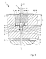
- a setting tool 7 is preferably used for setting the fastening element 4.
- Fig. 2 shows the setting tool 7 when setting the fastener 4 in one Fig. 1 corresponding, schematic section.
- Fig. 3 the proposed setting tool 7 in isolation.
- the setting tool 7 preferably has a head 7A, a shank 7B, a drive section 7C, a receiving area 7D for the fastening element 4, a cutting edge 7E and / or a stop 7F.
- the head 7A is preferably non-rotatably connected to the drive section 7C via the shaft 7B.
- the drive section 7C serves to receive and hold the setting tool 7 in a suitable rotary drive, in particular a cordless screwdriver, a drill or the like.
- the drive section 7C is formed, for example, as a projection or polygon. However, this can also be a possibility of intervention for a polygon, a bit or the like.
- the head 7A of the setting tool 7 is inserted into the opening 4B of the fastening element 4 and the fastening element 4 or its plate section 4A is received in the receiving area 7D of the setting tool 7.
- the cutting edge 7E projects laterally and / or fully along the circumference of the fastening element 4 or the plate section 4A axially or in the direction of insertion E over the peripheral edge of the plate section 4A.
- the setting tool 7 or its head 7A preferably has an in particular at least substantially cylindrical tip 7G which passes through the fastening element 4 or its opening 4B or projection 4C forwards, ie in the direction of insertion E or towards the insulation board 2 Structure 3 protrudes.
- the setting tool 7 is inserted with the tip 7G in a corresponding bore 8 and thereby guided laterally.
- the diameter of the tip 7G is therefore preferably adapted to the diameter of the bore 8 accordingly.
- the diameter of the tip 7G corresponds at least substantially to the inner diameter of the bore 8.
- the setting tool 7 After setting of the setting tool 7 to the associated bore 8, the setting tool 7 is set in rotation or rotation and advanced under pressure in the axial direction or insertion direction E to bring the front of the setting tool 7 arranged fastener 4 in the insulation board 2, so to put.
- the fastening element 4 is thus introduced by means of the setting tool 7 from the outside 2B of the insulation board 2 ago in the insulation board 2.
- the fastening element 4 is rotated or set during setting or setting by means of the setting tool 7.
- the setting tool 7 or its head 7A can engage or engage in a rotationally fixed manner on or in the fastening element 4 or its opening 4B or its engagement section 4D.
- the head 7A preferably has an engaging portion 7H which engages with the engaging portion 4D with the fastener 4 mounted on the setting tool 7.
- the engagement region 7H is preferably at least substantially conical or tapered in the insertion direction E or towards the front and / or provided with a non-circular, in particular polygonal outer contour, so that between the engagement portion 4D and the engagement region 7H and thus between the setting tool 7 and the fastening element 4, the desired rotational coupling, in particular by radial and / or axial Intervention, when setting the fastener 4 allows or ensured.
- the head 7A or its engagement region 7H forms an axial stop for the patch fastener 4.
- the axial stop for the fastening element 4 on the setting tool 7 may also be formed by another component.
- the fastener 4 When setting the fastener 4 is preferably introduced or driven in advance with its projection 4C and the insertion bevel 4F in the insulation board 2.
- the insertion bevel 4F and the projection 4C displace insulating material around the bore 8, in particular laterally or radially. This insertion and displacement is facilitated by the rotation of the fastener 4.
- the cutting edge 7E of the setting tool 7 intersects the insulating material or the insulating board 2 in a circular manner.
- the insulation material lying between the inner surface of the cutting edge 7E and the projection 4C under the disk portion 4A in an intermediate region 2C is ground or milled by the axially forwardly moving disk portion 4C, in particular supported or facilitated by the optionally provided profiling, toothing 4G or the like.
- the toothing 4G can preferably also continue on the outside on the projection 4C, in particular in the region of a conical section of the projection 4C adjoining the plate section 4A.
- the crushed insulating material, loose insulating material and / or milling dust is preferably held at least substantially completely below the fastening element 4 or its plate section 4A. This ensures in particular an opening-free design of the fastener 4 and Tellerabitess 4A.
- the fastening element 4 or its plate section 4A lies circumferentially, preferably at least substantially, tightly against the inner wall of the setting tool 7 or the cutting edge 7E. This is particularly supported or facilitated by the preferred fit or interference fit. This prevents or minimizes the formation of scrape dust on the outside of the plate section 4A.
- the fastening element 4 or the cup portion 4A may also circumferentially have an axially projecting edge, lip portion or the like, in particular to improve the circumferential seal or system.
- this peripheral edge may also be at least substantially cylindrical and / or protrude in the axial direction or insertion direction E, and / or form or replace the cutting edge 7E or support.
- the cutting edge 7E or the hollow-cylindrical region or sleeve region forming it can then be shorter or completely eliminated.
- the setting stop S indicates, in particular, the spacing of the fastening element 4 or plate section 4A from the outside 2B of the insulating board 2, as in FIG Fig. 2 indicated.
- the stopper 7F preferably protrudes laterally or radially, so that it comes to rest on reaching the desired setting depth S on the outside 2B of the insulating panel 2.
- the stopper 7F can also be axially adjustable, in particular in stages, in order to allow adaptation of the setting depth S or of different setting depths S, particularly preferably for adaptation to different insulating panel thicknesses.
- the setting tool 7 After reaching the desired setting depth S or after introduction or setting of the fastening element 4, the setting tool 7 is pulled out.
- the fastening element 4 remains here in the insulation board 2, in particular on Reason of frictionally and / or clamped in the insulating material or in the insulation board 2 seated projection 4C of the fastener. 4
- a depression 2D in the insulating board 2 is produced by the fastening element 4 or setting tool 7.
- This depression 2D is in particular at least substantially cylindrical and / or designed in the manner of a counterbore.
- the diameter of the depression 2D preferably corresponds at least essentially to the outside diameter of the fastening element 4 or plate section 4A or the cutting edge 7E, in particular in the region of the leading end or edge of the cutting edge 7E.
- the depression 2D can be conical, partially or completely.
- the depression 2D is preferably flared outwardly in a region adjacent to the outside 2B of the insulation board 2. This conical enlargement is preferably achieved by a corresponding radial widening of the insulating material by the setting tool 7.
- the setting tool 7, in the illustrated embodiment, preferably has a widened outer contour corresponding to the stop 7F.
- the cutting edge 7E is preferably formed in the illustrated example by a hollow cylindrical portion or sleeve portion, which forms or defines in particular a cylindrical outer contour of the tool 7 and in any case also - in particular to stop 7F out - conically formed or widened.
- the setting tool 7 preferably has a housing part 7J which forms the axially projecting cutting edge 7E and / or the preferably at least substantially cylindrical outer contour of the tool 7 and / or which forms or bears the stopper 7F or is connected thereto.
- the housing part 7J is preferably made of metal and / or the housing part 7J connects the cutting edge 7E in a rotationally fixed manner to the drive section 7C or shaft 7B or head 7A and / or stop 7F.
- the housing part 7J connects the cutting edge 7E in a rotationally fixed manner to the drive section 7C or shaft 7B or head 7A and / or stop 7F.
- other constructive solutions are possible here.
- the stopper 7F is preferably formed by a plate-like or disk-like element, which is particularly preferably flat and / or protrudes radially beyond the housing part 7J or the cutting edge 7E.
- the element is preferably connected to the housing part 7J.
- the fastening element 4 is connected to the structure 3 (permanently or highly loadable or in addition), in particular by a dowel connection or in any other suitable manner.
- This (second) connecting the insulation board 2 in addition to the bonding is preferably carried out in all fasteners 4, even if this is described below by way of example only for a fastener 4.
- the dowel 5, preferably with preassembled expansion element, in particular with partially screwed screw 6, is inserted or inserted into the insulation board 2 and the opening 4C and the subsequent bore 8, at least partially. This can be done manually.
- the complete insertion of the anchor 5 can also be done with the aid of a tool or impact element, such as a hammer.
- the dowel 5 extends by a desired amount or sufficiently far for a firm anchorage in the structure.
- Fig. 4 shows in one too Fig. 1 and 2 Corresponding, schematic section of the set fastener 4 with fully inserted dowel 5, but not yet fully inserted spreader, so with not (completely) screwed screw 6.
- An attached to the expansion element or the screw 6 screw 9 is shown.
- This screwing 9 can also be used for (complete) insertion of the anchor 5.
- the screwing-in tool 9 preferably has a marking or display 9D which indicates, for example, the complete insertion of the plug 5 in that the display 9D or a corresponding, in particular disk-like display element, a marking or the like lies in the plane of the outside 2B of the insulating board 2 , as in Fig. 4 indicated.
- the dowel 5 When completely inserted dowel 5, the dowel 5 extends in the bore 8 into the building 3 and is taken with its far end of the building in the receptacle 4 E of the fastener 4.
- a non-positive or positive connection between the dowel 5 and the fastener 4 and the receptacle 4E is formed at (fully) imported dowel 5 such that the fastener 4 is axially secured or held by the dowel 5, that is axially of the Dowel 5 is not removable.
- this dowel 5 sets with its preferably conically widened insulation board side or outer end of the particular complementary or also conical inner surface of the receptacle 4E.
- other constructive solutions are possible.
- a screw-9 for example, a screwdriver or other available on the site hand tool can be used.
- the Einschraubwerkmaschine 9 serves to tightening or tightening the dowel connection, ie in particular the screwing of the screw 6 in the dowel. 5
- the proposed insertion according to particularly preferred Einschraubwerkmaschine 9 preferably has the aforementioned display 9D.
- the screw-in tool 9 in particular has a head 9A, a shaft 9B and a drive section 9C.
- the head 9A is designed for the rotationally fixed engagement on the screw 6 or its screw head 6A.
- the tool head 9A is preferably a bit, a crosshead, polygonal, hexagon or other insert or polygonal key, which in particular can be brought into positive engagement with the expanding element or the screw 6 or its head 6A and / or or which is preferably replaceable.
- the tool 9 or the shank 9B is preferably designed to be received in a screwdriver or the like, and therefore provided in particular with the drive gate 9C, which is preferably designed as a polygon, at least in some areas.
- Fig. 4 shows the not completely introduced spreader.
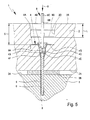
- Fig. 5 shows in a corresponding representation, the fully inserted spreader, ie the state with fully screwed screw 6.
- the fully screwed state of the screw head 6A is preferably on the outer or insulation board side end of the anchor 5 at.
- the front in the direction of insertion E end of the screw 6 has the dowel 5 spread apart in the structure 3 and thereby anchored or fixed. In this state, the fastener 4 is thus firmly connected to the structure 3 or pegged.
- the complete screwing of the screw 6 may, if necessary, by an additional display, marking or the like on the tool 9 are displayed to the user.
- the insertion length L, about which the expansion element is inserted or the screw 6 is screwed in, is preferably smaller than the insertion depth S of the fastening element 4. This represents a particular advantage of the proposed system 1 or the proposed method.
- the insertion depth S of the fastening element 4 is namely independent of the engagement length L.
- the screw-in length L in the present invention preferably refers to the extent to which the expansion element or the screw 6 is driven or screwed into the dowel 5 in order to spread the dowel 5 in the structure 3 and definitively fix or anchor it.
- this engagement length L is the length at which the dowel 5 or the expansion element or the screw 6 projects into the structure 3 in the pinned state.
- the proposed system 1 and the proposed method are characterized in particular by the fact that the setting of the fastener 4 is independent of the insertion of the expansion element or screwing the screw 6 so independent of the anchoring done.
- the proposed system 1, the proposed fastener 4 and the proposed method are characterized in particular by the fact that first a setting of the fastener 4 is done or possible and that after setting the connection with the structure 3, in particular the dowelling or pegging, takes place or is possible.
- dowels 5 or standard dowels 5, particularly preferably with preassembled expansion element or preassembled - ie partially screwed - screw 6, can be used with particular preference.
- the plug 2E is preferably made of a thermally insulating material or preferably made of the same or a similar insulating material as the insulation board 2.
- the preferred use of the same or similar insulating material for the plug 2E as for the insulation board 2 has the advantage that no introduction of different materials in the insulation board 2 takes place. This is particularly advantageous in terms of an outside cover and an outside plastering of the system 1 and the insulating board 2, since otherwise often resulting in the area of depression 2D or fasteners 4 resulting markings can be avoided.
- the plug 2E is preferably pressed into the depression 2D. Accordingly, the plug 2E preferably has a certain radial excess.
- the stopper 2E preferably has a shape corresponding at least substantially to the shape of the depression 2D.
- the inserted plug 2E preferably terminates flush with the outer side 2B of the insulation board.
- the plug 2E may extend in the inserted state to the fastening element 4 or rest on this, or alternatively ends at a distance from it.
- the plug 2E preferably has a greater thickness in the direction of insertion E than the engagement length L.
- the plug E prevents a thermal bridge in the region of the recess 2D to the outside, even if the expansion element or the screw 6 - as usual - preferably made of metal and therefore good thermal conductivity.
- the outer side 2B of the insulation board 2 can be plastered as needed.
- This plaster is in particular a material or a construction based on mineral, plastic or the like which is preferably reinforced by a fabric.
- the plaster is preferably made very thin and in particular forms a relative to the insulating material or the insulation board 2 relatively hard surface and / or protects the insulation board 2 from environmental influences, such as driving rain, compressive stress, solar radiation o.
- Fig. 6 shows in one too Fig. 4 Corresponding, schematic section of a slightly modified according to a variant variant Einschraubtechnikmaschine 9.
- the plug 2E is introduced directly from the screw 9 with.
- the plug 2E is attached to the shaft 9B.
- the display 9D is not used here to indicate the complete insertion of the anchor 5 in the fastener 6, but displaying the complete screwing the screw 6. Accordingly, the display 9D is arranged differently here and in particular larger in diameter, so that when fully screwed screw 6, the display 9D comes to rest on the outside 2B of the insulation board 2.
- the plug 2E is then preferably pushed to the display 9D on the shaft 9B.
- the plug 2E When the screw 6 is completely screwed in, the plug 2E preferably sits flush in the depression 2D. In this position, the Plug 2E held in particular by a corresponding frictional engagement or clamping fit with the insulating 2D forming insulation, so that the tool 9 and the shaft 9B can be pulled out without moving out of the plug 2E. Subsequently, only the thin hole for the shaft 9B must be closed, wherein the plug 2E can also be designed such that this hole or the opening closes itself to the outside. For example, correspondingly automatically resetting lamellae or the like may be arranged at the opening region of the stopper 2E towards the outside.
- Fig. 7 shows in one too Fig. 2 Corresponding, schematic section, the setting of a fastener 4 with a slightly modified setting tool 7.
- the respective insulation board 2 pierced and the structure 3 drilled, so the bore 8 formed. This simplifies the assembly or the process, since a previous drilling can be omitted.
- the setting tool 7 is designed for the aforementioned drilling or production of the bore 8.
- the head 7A or the tip 7G of the setting tool 7 is designed as a drill or, particularly preferably, designed to receive a drill.
- the tool head 7A is then designed in particular as a chuck for receiving a corresponding drill.
- the outer or circumferential cutting edge 7E leads to a clean cut in the insulating material or the insulation board 2. Accordingly, the plug 2E can be used very clean and / or good sealing later. Next, the emergence of milling dust, loose insulation or the like is avoided.
- the cutting edge 7E is according to the proposal in particular arranged on the setting tool 7 or formed by this.
- the cutting edge 7E is formed by a cutting plate.
- the cutting edge 7E can also be formed directly by the fastening element 4 or its plate section 4A or arranged thereon.
- the cutting edge 7E projecting axially or in the direction of introduction E causes shielding or masking before the grinding or milling of the insulating material takes place through the plate section 4E.
- the cutting edge 7E leads to a good guidance of the setting tool 7 and thus also of the fastening element 4 during insertion or setting, ie during milling.
- the setting tool 7 or fastening element 4 is particularly preferably when setting at high speed, in particular at more than 100 revolutions per minute, more preferably at more than 200 revolutions per minute and very particularly preferably at more than 500 revolutions per minute, possibly even with about 1000 revolutions per minute or higher, turned.
- the insulating material in the intermediate region 2C can be ground or milled according to the proposal and then occupies a significantly smaller or negligible volume.
- the perforation-free design of the fastening element 4 or plate section 4A prevents loose insulating material or milling dust or the like from escaping outwards, in particular when the setting tool 7 is removed.
- the preferably provided toothing 4G and / or other insulation board-side profiling of the fastening element 4 or plate section 4A is preferably designed such that a very fine grinding or milling of the insulating material takes place.
- the projection 4C of the fastening element 4 is preferably held by a radial interference fit in the insulating material or in the insulation board 2 with fastener 4 set. This ensures that the setting tool 7 can be removed and at the same time the fastening element 4 is held in the insulation board 2.
- the fastening element 4 or the plate section 4A need not be flat on the surface or on the outside.
- an insertion opening is formed on the fastening element 4 or on the opening 4B or the engagement section 4D. This facilitates the placement or sliding of the fastener 4 on the setting tool 7 or vice versa.
- the optional conical widening of the depression 2D or broadening of the setting tool 7 or housing part 7I allows improved guidance of the setting tool 7 and / or supports an optimum or flush seat when inserting the stopper 2E.
- the fastening element 4 can initially also be set with a somewhat larger setting depth S or milled up to a larger setting depth S in order to take into account a possible return effect due to the elasticity of the insulating material.
- the fastening element 4 can then move back slightly in the direction of the outer surface 2B of the insulating panel 2 after or during the removal of the setting tool 7, in order then to be pegged in this position to the building 3.
- the wells 2D of the insulation board 2 can be closed optimally and well insulated. Defects in the insulation board 2 can be avoided. In particular, no thermal bridge is formed. There is no hindrance to diffusion processes. Furthermore, optimal sound insulation properties can be achieved.
- the dowels 5 which can be used according to the proposal allow for logistical advantages, in particular a low transport volume and / or lower stocks of stock, since standard dowels can be used. Next, only small volumes of dowels 5 must be handled at the construction site.
- the insulating board 2 can be adhered to the building 3 as before.
Landscapes
- Engineering & Computer Science (AREA)
- Physics & Mathematics (AREA)
- Architecture (AREA)
- Acoustics & Sound (AREA)
- Electromagnetism (AREA)
- Civil Engineering (AREA)
- Structural Engineering (AREA)
- Mechanical Engineering (AREA)
- Building Environments (AREA)
- Working Measures On Existing Buildindgs (AREA)
Applications Claiming Priority (1)
| Application Number | Priority Date | Filing Date | Title |
|---|---|---|---|
| DE102012005207 | 2012-03-16 |
Publications (3)
| Publication Number | Publication Date |
|---|---|
| EP2639374A2 true EP2639374A2 (fr) | 2013-09-18 |
| EP2639374A3 EP2639374A3 (fr) | 2014-11-26 |
| EP2639374B1 EP2639374B1 (fr) | 2018-06-13 |
Family
ID=47912841
Family Applications (1)
| Application Number | Title | Priority Date | Filing Date |
|---|---|---|---|
| EP13001244.6A Not-in-force EP2639374B1 (fr) | 2012-03-16 | 2013-03-12 | Fixation de plaques d'isolation |
Country Status (1)
| Country | Link |
|---|---|
| EP (1) | EP2639374B1 (fr) |
Cited By (4)
| Publication number | Priority date | Publication date | Assignee | Title |
|---|---|---|---|---|
| EP2957686A1 (fr) * | 2014-06-17 | 2015-12-23 | ITW Construction Products CZ s.r.o. | Gabarit de réglage d'un élément de dilatation oblongue dans une douille |
| EP2959995A1 (fr) | 2014-06-23 | 2015-12-30 | EJOT Baubefestigungen GmbH | Outil de montage et procédé d'installation en retrait d'une rosace de cheville |
| EP3428358A1 (fr) | 2017-07-12 | 2019-01-16 | fischerwerke GmbH & Co. KG | Dispositif de maintien de matériau isolant |
| EP3354812B1 (fr) * | 2017-01-25 | 2023-07-05 | EJOT Baubefestigungen GmbH | Système de fixation d'une plaque isolante |
Citations (8)
| Publication number | Priority date | Publication date | Assignee | Title |
|---|---|---|---|---|
| EP0086452A2 (fr) | 1982-02-12 | 1983-08-24 | Fäster GmbH & Co. KG Befestigungstechnik | Procédé de fixation d'une dalle isolante à enduire à une surface de bâtiment |
| DE19536171A1 (de) | 1995-09-28 | 1997-04-03 | Ejot Kunststofftech Gmbh | Befestigungselement für die Befestigung von wärmeisolierenden Materialien |
| EP1318250A2 (fr) | 2001-12-05 | 2003-06-11 | EJOT Kunststofftechnik GmbH & Co. KG | Cheville et méthode de montage de panneaux isolants |
| DE102006006164A1 (de) | 2006-02-10 | 2007-08-23 | Ranit-Befestigungssysteme Gmbh | Befestigungssystem für Bauteile an einen tragenden Untergrund sowie Verfahren und Montagehilfe zur Anbringung des Befestigungssystems |
| DE102006060538A1 (de) | 2006-05-15 | 2007-11-22 | Fischerwerke Artur Fischer Gmbh & Co. Kg | Befestigungselement und Verfahren zur Befestigung von Dämmstoffplatten |
| DE102007000235A1 (de) | 2007-04-20 | 2008-10-23 | Hilti Aktiengesellschaft | Setzwerkzeug für einen Dämmstoffdübel |
| DE102007046323B3 (de) | 2007-09-27 | 2009-07-23 | Ejot Baubefestigungen Gmbh | Befestigungselement und Verfahren zur vertieften Montage einer Dämmstoffplatte |
| DE102011016383A1 (de) | 2010-04-15 | 2011-12-15 | Ranit Befestigungssysteme Gmbh | Verfahren sowie Werkzeug und Abdeckscheibe zur Montage einer Dämmstoffplatte an einer Unterkonstruktion |
Family Cites Families (6)
| Publication number | Priority date | Publication date | Assignee | Title |
|---|---|---|---|---|
| WO1988005487A1 (fr) * | 1987-01-21 | 1988-07-28 | Sfs Stadler Ag | Element de fixation a rondelle a grande surface |
| FR2694319B1 (fr) * | 1992-07-30 | 1995-02-24 | Sicof Ste Indle Cale Facade | Panneau pour habillage isolant des parois de bâtiments. |
| DE10336795A1 (de) * | 2003-08-08 | 2005-03-10 | Saint Gobain Isover G & H Ag | Wärmedämmverbundsystem |
| DE102004006936A1 (de) * | 2004-02-12 | 2005-09-01 | Friedr. Trurnit Gmbh | Werkzeug zum Einbringen von Dämmstoffschrauben mit daran vorgesehenem Druckteller in eine Dämmstoffplatte oder dergleichen |
| DE102007053740B3 (de) * | 2007-11-12 | 2009-01-15 | Ejot Baubefestigungen Gmbh | Universaldübel für Wärmedämmverbundsysteme |
| US20110067224A1 (en) * | 2009-09-18 | 2011-03-24 | Ulrich Knebel | Fastening system with fabric layers |
-
2013
- 2013-03-12 EP EP13001244.6A patent/EP2639374B1/fr not_active Not-in-force
Patent Citations (8)
| Publication number | Priority date | Publication date | Assignee | Title |
|---|---|---|---|---|
| EP0086452A2 (fr) | 1982-02-12 | 1983-08-24 | Fäster GmbH & Co. KG Befestigungstechnik | Procédé de fixation d'une dalle isolante à enduire à une surface de bâtiment |
| DE19536171A1 (de) | 1995-09-28 | 1997-04-03 | Ejot Kunststofftech Gmbh | Befestigungselement für die Befestigung von wärmeisolierenden Materialien |
| EP1318250A2 (fr) | 2001-12-05 | 2003-06-11 | EJOT Kunststofftechnik GmbH & Co. KG | Cheville et méthode de montage de panneaux isolants |
| DE102006006164A1 (de) | 2006-02-10 | 2007-08-23 | Ranit-Befestigungssysteme Gmbh | Befestigungssystem für Bauteile an einen tragenden Untergrund sowie Verfahren und Montagehilfe zur Anbringung des Befestigungssystems |
| DE102006060538A1 (de) | 2006-05-15 | 2007-11-22 | Fischerwerke Artur Fischer Gmbh & Co. Kg | Befestigungselement und Verfahren zur Befestigung von Dämmstoffplatten |
| DE102007000235A1 (de) | 2007-04-20 | 2008-10-23 | Hilti Aktiengesellschaft | Setzwerkzeug für einen Dämmstoffdübel |
| DE102007046323B3 (de) | 2007-09-27 | 2009-07-23 | Ejot Baubefestigungen Gmbh | Befestigungselement und Verfahren zur vertieften Montage einer Dämmstoffplatte |
| DE102011016383A1 (de) | 2010-04-15 | 2011-12-15 | Ranit Befestigungssysteme Gmbh | Verfahren sowie Werkzeug und Abdeckscheibe zur Montage einer Dämmstoffplatte an einer Unterkonstruktion |
Cited By (5)
| Publication number | Priority date | Publication date | Assignee | Title |
|---|---|---|---|---|
| EP2957686A1 (fr) * | 2014-06-17 | 2015-12-23 | ITW Construction Products CZ s.r.o. | Gabarit de réglage d'un élément de dilatation oblongue dans une douille |
| EP2959995A1 (fr) | 2014-06-23 | 2015-12-30 | EJOT Baubefestigungen GmbH | Outil de montage et procédé d'installation en retrait d'une rosace de cheville |
| EP3354812B1 (fr) * | 2017-01-25 | 2023-07-05 | EJOT Baubefestigungen GmbH | Système de fixation d'une plaque isolante |
| EP3428358A1 (fr) | 2017-07-12 | 2019-01-16 | fischerwerke GmbH & Co. KG | Dispositif de maintien de matériau isolant |
| DE102017115628A1 (de) | 2017-07-12 | 2019-01-17 | Fischerwerke Gmbh & Co. Kg | Dämmstoffhalter |
Also Published As
| Publication number | Publication date |
|---|---|
| EP2639374A3 (fr) | 2014-11-26 |
| EP2639374B1 (fr) | 2018-06-13 |
Similar Documents
| Publication | Publication Date | Title |
|---|---|---|
| EP1870533B1 (fr) | Procédé de montage de plaques de matériau isolant | |
| EP0086452B1 (fr) | Procédé de fixation d'une dalle isolante à enduire à une surface de bâtiment | |
| EP1857607B1 (fr) | Elément et méthode de fixation de panneaux isolants | |
| EP2042666B1 (fr) | Elément de fixation et procédé de montage en retrait d'une plaque de matériau isolant | |
| EP2378019B1 (fr) | Procédé, ainsi qu'outil pour le montage d'une plaque isolante sur une sous-construction | |
| EP1818477A2 (fr) | Système de fixation pour composants sur un sous-sol porteur ainsi que procédé et aide au montage destinés à l'installation du système de fixation | |
| EP2639374B1 (fr) | Fixation de plaques d'isolation | |
| DE10159632B4 (de) | Dübel und Verfahren zur Montage von Dämmstoffplatten sowie eine Vorrichtung zum Eintreiben eines Spreizelements in einen Dübel | |
| DE3321623C2 (de) | Isolierplattendübel aus Kunststoff | |
| EP1691086B1 (fr) | Fixation pour matériau isolant | |
| DE102010045445A1 (de) | Montagesystem für Isolierstoffplatten | |
| EP1591602B1 (fr) | Système pour fixer des éléments de construction sur un mur | |
| EP3702629B1 (fr) | Ensemble de montage universel permettant de monter un cadre sur un terrain naturel | |
| EP1417418A1 (fr) | Cheville de plaque d'isolation | |
| DE10213490A1 (de) | Verfahren und Vorrichtung zur Montage von Dämmstoffplatten | |
| DE102012022574B4 (de) | Befestigungselement | |
| DE202012006363U1 (de) | System, Befestigungselement und Werkzeug zur Befestigung von Dämmplatten | |
| DE102004005582A1 (de) | Dübelvorrichtung zur Verankerung von Wärmedämmplatten | |
| DE102016110478A1 (de) | Befestigungselement mit Schraubabschnitt und Gleitschaft | |
| EP3354812A1 (fr) | Système de fixation d'une plaque isolante | |
| EP2511440B1 (fr) | Système, outil et procédé de fixation de plaques d'isolation | |
| EP1857608A2 (fr) | Procédé, cheville de retenue et outil de forage pour fixer ultérieurment des panneaux isolants à un mur | |
| EP2915929A1 (fr) | Procédé et système de fixation destinés à appliquer des plaques de laine minérale sur un sous-sol porteur |
Legal Events
| Date | Code | Title | Description |
|---|---|---|---|
| PUAI | Public reference made under article 153(3) epc to a published international application that has entered the european phase |
Free format text: ORIGINAL CODE: 0009012 |
|
| AK | Designated contracting states |
Kind code of ref document: A2 Designated state(s): AL AT BE BG CH CY CZ DE DK EE ES FI FR GB GR HR HU IE IS IT LI LT LU LV MC MK MT NL NO PL PT RO RS SE SI SK SM TR |
|
| AX | Request for extension of the european patent |
Extension state: BA ME |
|
| PUAL | Search report despatched |
Free format text: ORIGINAL CODE: 0009013 |
|
| AK | Designated contracting states |
Kind code of ref document: A3 Designated state(s): AL AT BE BG CH CY CZ DE DK EE ES FI FR GB GR HR HU IE IS IT LI LT LU LV MC MK MT NL NO PL PT RO RS SE SI SK SM TR |
|
| AX | Request for extension of the european patent |
Extension state: BA ME |
|
| RIC1 | Information provided on ipc code assigned before grant |
Ipc: E04B 1/76 20060101AFI20141021BHEP |
|
| 17P | Request for examination filed |
Effective date: 20150422 |
|
| RBV | Designated contracting states (corrected) |
Designated state(s): AL AT BE BG CH CY CZ DE DK EE ES FI FR GB GR HR HU IE IS IT LI LT LU LV MC MK MT NL NO PL PT RO RS SE SI SK SM TR |
|
| TPAC | Observations filed by third parties |
Free format text: ORIGINAL CODE: EPIDOSNTIPA |
|
| RAP1 | Party data changed (applicant data changed or rights of an application transferred) |
Owner name: EJOT BAUBEFESTIGUNGEN GMBH |
|
| RIN1 | Information on inventor provided before grant (corrected) |
Inventor name: EJOT BAUBEFESTIGUNGEN GMBH |
|
| 17Q | First examination report despatched |
Effective date: 20151014 |
|
| REG | Reference to a national code |
Ref country code: DE Ref legal event code: R079 Ref document number: 502013010353 Country of ref document: DE Free format text: PREVIOUS MAIN CLASS: E04B0001760000 Ipc: B23B0051080000 |
|
| GRAP | Despatch of communication of intention to grant a patent |
Free format text: ORIGINAL CODE: EPIDOSNIGR1 |
|
| INTG | Intention to grant announced |
Effective date: 20160922 |
|
| RIC1 | Information provided on ipc code assigned before grant |
Ipc: E04B 1/76 20060101ALI20160909BHEP Ipc: B23B 51/08 20060101AFI20160909BHEP |
|
| GRAJ | Information related to disapproval of communication of intention to grant by the applicant or resumption of examination proceedings by the epo deleted |
Free format text: ORIGINAL CODE: EPIDOSDIGR1 |
|
| STAA | Information on the status of an ep patent application or granted ep patent |
Free format text: STATUS: EXAMINATION IS IN PROGRESS |
|
| GRAP | Despatch of communication of intention to grant a patent |
Free format text: ORIGINAL CODE: EPIDOSNIGR1 |
|
| STAA | Information on the status of an ep patent application or granted ep patent |
Free format text: STATUS: GRANT OF PATENT IS INTENDED |
|
| RIN1 | Information on inventor provided before grant (corrected) |
Inventor name: TIEMANN, JOACHIM |
|
| INTG | Intention to grant announced |
Effective date: 20161111 |
|
| TPAC | Observations filed by third parties |
Free format text: ORIGINAL CODE: EPIDOSNTIPA |
|
| GRAJ | Information related to disapproval of communication of intention to grant by the applicant or resumption of examination proceedings by the epo deleted |
Free format text: ORIGINAL CODE: EPIDOSDIGR1 |
|
| STAA | Information on the status of an ep patent application or granted ep patent |
Free format text: STATUS: EXAMINATION IS IN PROGRESS |
|
| INTC | Intention to grant announced (deleted) | ||
| GRAP | Despatch of communication of intention to grant a patent |
Free format text: ORIGINAL CODE: EPIDOSNIGR1 |
|
| STAA | Information on the status of an ep patent application or granted ep patent |
Free format text: STATUS: GRANT OF PATENT IS INTENDED |
|
| INTG | Intention to grant announced |
Effective date: 20180122 |
|
| GRAS | Grant fee paid |
Free format text: ORIGINAL CODE: EPIDOSNIGR3 |
|
| GRAA | (expected) grant |
Free format text: ORIGINAL CODE: 0009210 |
|
| STAA | Information on the status of an ep patent application or granted ep patent |
Free format text: STATUS: THE PATENT HAS BEEN GRANTED |
|
| AK | Designated contracting states |
Kind code of ref document: B1 Designated state(s): AL AT BE BG CH CY CZ DE DK EE ES FI FR GB GR HR HU IE IS IT LI LT LU LV MC MK MT NL NO PL PT RO RS SE SI SK SM TR |
|
| REG | Reference to a national code |
Ref country code: GB Ref legal event code: FG4D Free format text: NOT ENGLISH |
|
| REG | Reference to a national code |
Ref country code: CH Ref legal event code: EP Ref country code: AT Ref legal event code: REF Ref document number: 1007954 Country of ref document: AT Kind code of ref document: T Effective date: 20180615 |
|
| REG | Reference to a national code |
Ref country code: IE Ref legal event code: FG4D Free format text: LANGUAGE OF EP DOCUMENT: GERMAN |
|
| REG | Reference to a national code |
Ref country code: DE Ref legal event code: R096 Ref document number: 502013010353 Country of ref document: DE |
|
| REG | Reference to a national code |
Ref country code: NL Ref legal event code: MP Effective date: 20180613 |
|
| REG | Reference to a national code |
Ref country code: LT Ref legal event code: MG4D |
|
| PG25 | Lapsed in a contracting state [announced via postgrant information from national office to epo] |
Ref country code: ES Free format text: LAPSE BECAUSE OF FAILURE TO SUBMIT A TRANSLATION OF THE DESCRIPTION OR TO PAY THE FEE WITHIN THE PRESCRIBED TIME-LIMIT Effective date: 20180613 Ref country code: SE Free format text: LAPSE BECAUSE OF FAILURE TO SUBMIT A TRANSLATION OF THE DESCRIPTION OR TO PAY THE FEE WITHIN THE PRESCRIBED TIME-LIMIT Effective date: 20180613 Ref country code: NO Free format text: LAPSE BECAUSE OF FAILURE TO SUBMIT A TRANSLATION OF THE DESCRIPTION OR TO PAY THE FEE WITHIN THE PRESCRIBED TIME-LIMIT Effective date: 20180913 Ref country code: FI Free format text: LAPSE BECAUSE OF FAILURE TO SUBMIT A TRANSLATION OF THE DESCRIPTION OR TO PAY THE FEE WITHIN THE PRESCRIBED TIME-LIMIT Effective date: 20180613 Ref country code: LT Free format text: LAPSE BECAUSE OF FAILURE TO SUBMIT A TRANSLATION OF THE DESCRIPTION OR TO PAY THE FEE WITHIN THE PRESCRIBED TIME-LIMIT Effective date: 20180613 Ref country code: BG Free format text: LAPSE BECAUSE OF FAILURE TO SUBMIT A TRANSLATION OF THE DESCRIPTION OR TO PAY THE FEE WITHIN THE PRESCRIBED TIME-LIMIT Effective date: 20180913 Ref country code: CY Free format text: LAPSE BECAUSE OF FAILURE TO SUBMIT A TRANSLATION OF THE DESCRIPTION OR TO PAY THE FEE WITHIN THE PRESCRIBED TIME-LIMIT Effective date: 20180613 |
|
| PG25 | Lapsed in a contracting state [announced via postgrant information from national office to epo] |
Ref country code: GR Free format text: LAPSE BECAUSE OF FAILURE TO SUBMIT A TRANSLATION OF THE DESCRIPTION OR TO PAY THE FEE WITHIN THE PRESCRIBED TIME-LIMIT Effective date: 20180914 Ref country code: RS Free format text: LAPSE BECAUSE OF FAILURE TO SUBMIT A TRANSLATION OF THE DESCRIPTION OR TO PAY THE FEE WITHIN THE PRESCRIBED TIME-LIMIT Effective date: 20180613 Ref country code: LV Free format text: LAPSE BECAUSE OF FAILURE TO SUBMIT A TRANSLATION OF THE DESCRIPTION OR TO PAY THE FEE WITHIN THE PRESCRIBED TIME-LIMIT Effective date: 20180613 Ref country code: HR Free format text: LAPSE BECAUSE OF FAILURE TO SUBMIT A TRANSLATION OF THE DESCRIPTION OR TO PAY THE FEE WITHIN THE PRESCRIBED TIME-LIMIT Effective date: 20180613 |
|
| PG25 | Lapsed in a contracting state [announced via postgrant information from national office to epo] |
Ref country code: NL Free format text: LAPSE BECAUSE OF FAILURE TO SUBMIT A TRANSLATION OF THE DESCRIPTION OR TO PAY THE FEE WITHIN THE PRESCRIBED TIME-LIMIT Effective date: 20180613 |
|
| PG25 | Lapsed in a contracting state [announced via postgrant information from national office to epo] |
Ref country code: CZ Free format text: LAPSE BECAUSE OF FAILURE TO SUBMIT A TRANSLATION OF THE DESCRIPTION OR TO PAY THE FEE WITHIN THE PRESCRIBED TIME-LIMIT Effective date: 20180613 Ref country code: RO Free format text: LAPSE BECAUSE OF FAILURE TO SUBMIT A TRANSLATION OF THE DESCRIPTION OR TO PAY THE FEE WITHIN THE PRESCRIBED TIME-LIMIT Effective date: 20180613 Ref country code: SK Free format text: LAPSE BECAUSE OF FAILURE TO SUBMIT A TRANSLATION OF THE DESCRIPTION OR TO PAY THE FEE WITHIN THE PRESCRIBED TIME-LIMIT Effective date: 20180613 Ref country code: IS Free format text: LAPSE BECAUSE OF FAILURE TO SUBMIT A TRANSLATION OF THE DESCRIPTION OR TO PAY THE FEE WITHIN THE PRESCRIBED TIME-LIMIT Effective date: 20181013 Ref country code: EE Free format text: LAPSE BECAUSE OF FAILURE TO SUBMIT A TRANSLATION OF THE DESCRIPTION OR TO PAY THE FEE WITHIN THE PRESCRIBED TIME-LIMIT Effective date: 20180613 Ref country code: PL Free format text: LAPSE BECAUSE OF FAILURE TO SUBMIT A TRANSLATION OF THE DESCRIPTION OR TO PAY THE FEE WITHIN THE PRESCRIBED TIME-LIMIT Effective date: 20180613 |
|
| PG25 | Lapsed in a contracting state [announced via postgrant information from national office to epo] |
Ref country code: IT Free format text: LAPSE BECAUSE OF FAILURE TO SUBMIT A TRANSLATION OF THE DESCRIPTION OR TO PAY THE FEE WITHIN THE PRESCRIBED TIME-LIMIT Effective date: 20180613 Ref country code: SM Free format text: LAPSE BECAUSE OF FAILURE TO SUBMIT A TRANSLATION OF THE DESCRIPTION OR TO PAY THE FEE WITHIN THE PRESCRIBED TIME-LIMIT Effective date: 20180613 |
|
| REG | Reference to a national code |
Ref country code: DE Ref legal event code: R097 Ref document number: 502013010353 Country of ref document: DE |
|
| PLBE | No opposition filed within time limit |
Free format text: ORIGINAL CODE: 0009261 |
|
| STAA | Information on the status of an ep patent application or granted ep patent |
Free format text: STATUS: NO OPPOSITION FILED WITHIN TIME LIMIT |
|
| 26N | No opposition filed |
Effective date: 20190314 |
|
| PG25 | Lapsed in a contracting state [announced via postgrant information from national office to epo] |
Ref country code: DK Free format text: LAPSE BECAUSE OF FAILURE TO SUBMIT A TRANSLATION OF THE DESCRIPTION OR TO PAY THE FEE WITHIN THE PRESCRIBED TIME-LIMIT Effective date: 20180613 Ref country code: SI Free format text: LAPSE BECAUSE OF FAILURE TO SUBMIT A TRANSLATION OF THE DESCRIPTION OR TO PAY THE FEE WITHIN THE PRESCRIBED TIME-LIMIT Effective date: 20180613 |
|
| PG25 | Lapsed in a contracting state [announced via postgrant information from national office to epo] |
Ref country code: MC Free format text: LAPSE BECAUSE OF FAILURE TO SUBMIT A TRANSLATION OF THE DESCRIPTION OR TO PAY THE FEE WITHIN THE PRESCRIBED TIME-LIMIT Effective date: 20180613 |
|
| REG | Reference to a national code |
Ref country code: CH Ref legal event code: PL |
|
| GBPC | Gb: european patent ceased through non-payment of renewal fee |
Effective date: 20190312 |
|
| PG25 | Lapsed in a contracting state [announced via postgrant information from national office to epo] |
Ref country code: AL Free format text: LAPSE BECAUSE OF FAILURE TO SUBMIT A TRANSLATION OF THE DESCRIPTION OR TO PAY THE FEE WITHIN THE PRESCRIBED TIME-LIMIT Effective date: 20180613 Ref country code: LU Free format text: LAPSE BECAUSE OF NON-PAYMENT OF DUE FEES Effective date: 20190312 |
|
| REG | Reference to a national code |
Ref country code: BE Ref legal event code: MM Effective date: 20190331 |
|
| PG25 | Lapsed in a contracting state [announced via postgrant information from national office to epo] |
Ref country code: GB Free format text: LAPSE BECAUSE OF NON-PAYMENT OF DUE FEES Effective date: 20190312 Ref country code: CH Free format text: LAPSE BECAUSE OF NON-PAYMENT OF DUE FEES Effective date: 20190331 Ref country code: LI Free format text: LAPSE BECAUSE OF NON-PAYMENT OF DUE FEES Effective date: 20190331 Ref country code: IE Free format text: LAPSE BECAUSE OF NON-PAYMENT OF DUE FEES Effective date: 20190312 |
|
| PG25 | Lapsed in a contracting state [announced via postgrant information from national office to epo] |
Ref country code: BE Free format text: LAPSE BECAUSE OF NON-PAYMENT OF DUE FEES Effective date: 20190331 Ref country code: FR Free format text: LAPSE BECAUSE OF NON-PAYMENT OF DUE FEES Effective date: 20190331 |
|
| PG25 | Lapsed in a contracting state [announced via postgrant information from national office to epo] |
Ref country code: TR Free format text: LAPSE BECAUSE OF FAILURE TO SUBMIT A TRANSLATION OF THE DESCRIPTION OR TO PAY THE FEE WITHIN THE PRESCRIBED TIME-LIMIT Effective date: 20180613 |
|
| PG25 | Lapsed in a contracting state [announced via postgrant information from national office to epo] |
Ref country code: PT Free format text: LAPSE BECAUSE OF FAILURE TO SUBMIT A TRANSLATION OF THE DESCRIPTION OR TO PAY THE FEE WITHIN THE PRESCRIBED TIME-LIMIT Effective date: 20181015 Ref country code: MT Free format text: LAPSE BECAUSE OF FAILURE TO SUBMIT A TRANSLATION OF THE DESCRIPTION OR TO PAY THE FEE WITHIN THE PRESCRIBED TIME-LIMIT Effective date: 20180613 |
|
| REG | Reference to a national code |
Ref country code: AT Ref legal event code: MM01 Ref document number: 1007954 Country of ref document: AT Kind code of ref document: T Effective date: 20190312 |
|
| PG25 | Lapsed in a contracting state [announced via postgrant information from national office to epo] |
Ref country code: AT Free format text: LAPSE BECAUSE OF NON-PAYMENT OF DUE FEES Effective date: 20190312 |
|
| PG25 | Lapsed in a contracting state [announced via postgrant information from national office to epo] |
Ref country code: HU Free format text: LAPSE BECAUSE OF FAILURE TO SUBMIT A TRANSLATION OF THE DESCRIPTION OR TO PAY THE FEE WITHIN THE PRESCRIBED TIME-LIMIT; INVALID AB INITIO Effective date: 20130312 |
|
| PG25 | Lapsed in a contracting state [announced via postgrant information from national office to epo] |
Ref country code: MK Free format text: LAPSE BECAUSE OF FAILURE TO SUBMIT A TRANSLATION OF THE DESCRIPTION OR TO PAY THE FEE WITHIN THE PRESCRIBED TIME-LIMIT Effective date: 20180613 |
|
| PGFP | Annual fee paid to national office [announced via postgrant information from national office to epo] |
Ref country code: DE Payment date: 20240320 Year of fee payment: 12 |
|
| REG | Reference to a national code |
Ref country code: DE Ref legal event code: R119 Ref document number: 502013010353 Country of ref document: DE |
|
| PG25 | Lapsed in a contracting state [announced via postgrant information from national office to epo] |
Ref country code: DE Free format text: LAPSE BECAUSE OF NON-PAYMENT OF DUE FEES Effective date: 20251001 |