EP2639512A2 - Haushaltsgerät mit einer Lambda-Sonde bzw. Verfahren zum Betreiben eines Haushaltsgeräts mit einer Lambda-Sonde - Google Patents
Haushaltsgerät mit einer Lambda-Sonde bzw. Verfahren zum Betreiben eines Haushaltsgeräts mit einer Lambda-Sonde Download PDFInfo
- Publication number
- EP2639512A2 EP2639512A2 EP13157931.0A EP13157931A EP2639512A2 EP 2639512 A2 EP2639512 A2 EP 2639512A2 EP 13157931 A EP13157931 A EP 13157931A EP 2639512 A2 EP2639512 A2 EP 2639512A2
- Authority
- EP
- European Patent Office
- Prior art keywords
- probe
- lambda probe
- voltage
- buck converter
- sensor
- Prior art date
- Legal status (The legal status is an assumption and is not a legal conclusion. Google has not performed a legal analysis and makes no representation as to the accuracy of the status listed.)
- Granted
Links
Images


Classifications
-
- F—MECHANICAL ENGINEERING; LIGHTING; HEATING; WEAPONS; BLASTING
- F24—HEATING; RANGES; VENTILATING
- F24C—DOMESTIC STOVES OR RANGES ; DETAILS OF DOMESTIC STOVES OR RANGES, OF GENERAL APPLICATION
- F24C7/00—Stoves or ranges heated by electric energy
- F24C7/08—Arrangement or mounting of control or safety devices
- F24C7/082—Arrangement or mounting of control or safety devices on ranges, e.g. control panels, illumination
- F24C7/085—Arrangement or mounting of control or safety devices on ranges, e.g. control panels, illumination on baking ovens
Definitions
- the invention relates apparatus according to a household appliance with a lambda probe. According to the invention, the invention relates to a method for operating a household appliance with a lambda probe.
- Lambda probes are used in the motor vehicle and truck sector to optimize fuel combustion in the engine depending on the oxygen content.
- Lambda probes have a heating element as probe heating.
- the effective voltage U eff on the heating element is influenced or set by the pulsed switching with the aid of the switch-on duration t on per cycle or period T.
- the maximum value U Bat is applied to the heating element of the probe during the on-time t on, and a correspondingly large heating current with large peak values flows during this time.
- a household appliance with a lambda probe wherein the lambda probe is preceded by a buck converter or the lambda probe has a buck converter.
- a particular commercially available lambda probe with a predetermined operating voltage can nevertheless be operated at a higher supply voltage, e.g. in the event that the household appliance provides only such a higher supply voltage.
- the buck converter also referred to as a buck converter, step-down converter or buck converter
- a suitable voltage for operating the lambda probe, in particular the heating of the lambda probe can be converted from a higher voltage.
- the buck converter is arranged in a region between, for example, a housing of the lambda probe and a mains voltage connection within the household appliance.
- the buck converter is arranged in particular in a housing which receives the lambda probe, or assigned to the lambda probe functionally.
- a DC voltage can also be used, e.g. in the amount of 24 volts.
- the cooking appliance may comprise a hob, an oven (oven and / or microwave oven), a steamer or a vacuum cooker.
- the household appliance is equipped with a sensor, wherein the sensor of the lambda probe or at least one component of the lambda probe is connected upstream and wherein the sensor comprises the buck converter.
- the sensor system is designed as control electronics of the lambda probe.
- the peculiarity of the voltage conversion used is in this case according to an embodiment that the conversion does not already take place in the central power supply of the oven, but decentralized in the buck converter on the control electronics of the lambda probe. Accordingly, the control electronics of the lambda probe as well as other components of the household appliance also with a higher voltage (eg 24V), which already exists in the oven or other cooking appliance as an exemplary home appliance for other consumers supplied.
- a higher voltage eg 24V
- an output voltage of the buck converter is applied as a probe voltage to a probe heater of the lambda probe.
- a control or regulating device of the buck converter which provides a switching signal with such a frequency to a switch of the buck converter.
- the buck converter may have at least one switch which can be driven with such a frequency.
- the buck converter is designed as a SEPIC or as a uc-converter.
- CCM Continuous Conduction Mode
- the household appliance is designed as a cooking appliance and is applied to a controller for controlling a cooking automatic, in particular back-up, at least one measured variable or derived therefrom size of a sensor of the lambda probe.
- the above object is also achieved by a method for operating a lambda probe of a household appliance, in particular cooking appliance, in which at least one component of the lambda probe is operated by means of a step-down converter.
- the operation is understood to mean, in particular, supplying such a component with an operating voltage, triggering a functionality of the probe or a sensor system of the probe itself or else providing measured variables or parameters derived therefrom for other components of the household appliance.
- Such a parameter is, in particular, a measured variable which represents an oxygen content of the surroundings of the probe.
- the household appliance is controlled by means of the at least one parameter.
- the buck converter is driven with a frequency which is between 20 kHz and 150 kHz.
- lambda probes such as those used in the motor vehicle and truck sector
- a power supply e.g. in the amount of 12V ensures the supply of the heating of the lambda probe (probe heating).
- the 12V supply is achieved by means of the buck converter. This is also advantageous when e.g. no other electronic assembly in the oven needs a 12V supply.
- Fig.1 shows a section of an exemplary cooking appliance 101 and a lambda probe 102 connected thereto.
- the lambda probe 102 has a sensor 103 and a probe heater 104.
- the lambda probe 102 is connected to a controller 105 of the cooking appliance 101 via an interface 106.
- the lambda probe 102 is an example of part of a sensor 107.
- the sensor 107 may be arranged outside of the cooking appliance 101 or designed as part of the cooking appliance 101.
- a line 108 is connected to a buck converter 109 of the sensor 107.
- line 108 is located relative to ground 110 a supply voltage U in of, for example, to 24V.
- the ground terminal is connected via a line to the interface 106 and the mass of the cooking appliance.
- the buck converter 109 serves to convert the supply voltage U in to a probe voltage U out , for example 12 V, for operating the probe heater 104.
- the step-down converter 109 supplies the probe voltage U out via a line 111 of the probe heater 104, whose further connection is connected to ground 110.
- the sensor 107 is also connected via a signal or data line 112 to the interface 106 and the controller 105, via the signal or Data line 112 to transmit data or signals based on a measurand of the sensor 103.
- the buck converter 109 comprises a switch 113 which is connected in series with a coil 114, wherein a node 118 is arranged between the switch 113 and the coil 114.
- the node 118 is connected to the cathode of a diode 115, the anode of the diode is connected to ground 110.
- a capacitor 116 is arranged.
- the output of the buck converter 109 is connected to the probe heater 104.
- the switch 113 is driven by a switching signal 117 having a switching frequency f.
- the dimensioning of the buck converter 109 in conjunction with the switching signal 117 results in a corresponding conversion of the incoming voltage U in into the outgoing voltage U out , which is needed to operate the lambda probe 102, in particular the probe heater 104.
- the buck converter 109 prevents an excessively high voltage value from being applied to the lambda probe 102 and damaging it.
- Fig.2 shows a schematic representation of the sensor 107 with a sensor device 201, which is connected upstream of the lambda probe 102.
- the sensor device 201 comprises the step-down converter 109.
- the line 108 for the supply voltage U in leads into the sensor device 201 and again lies against the step-down converter 109, which is connected via the line 111 to the probe heater 104.
- the probe heater 104 as well as the sensor device 201 are each connected to ground 110.
- a sensor line 202 leads to the transmission of a measured variable 203 of the sensor 103 into the sensor device 201.
- the sensor line 202 is connected in the sensor device 201 in particular to a signal processing device 204 and to a control device 205 to which the measured variable 203 is applied.
- the signal processing device 204 is used for preprocessing the measured variable 203 and outputting corresponding (eg digitized) data onto the signal or data line 112.
- the regulating device 205 regulates the switching signal 117 (in particular the switching frequency f) and applies the switching signal 117 via a line 206 to the buck converter 109 or to its switch 113.
- the controller 205 may be configured as a so-called PI controller (i.e., a regulator having a proportional and an integrating portion).
- a monitoring device 207 is provided in the sensor device 201, which may be e.g. is connected via an analog-to-digital converter with the line 111 to the probe heater 104.
- the monitor 207 may be e.g. determine whether the voltage applied to the probe heater 104 is within an allowable range; if necessary, the monitoring device 207 can initiate a shutdown or a corresponding correction of the buck converter 109.
- a second line 208 leads from the interface 106 to the application of a further supply voltage Ux, for example, 5 V to the sensor device 201.
- This further supply voltage Ux is used to supply various components of the sensor device 201, such as the signal processing device 204, the controller 205 and the monitoring device 207, in particular (at least partially) by means of a program in a control unit, eg a microcontroller or microprocessor can be realized.
- a supply of the lambda probe 102 with the first supply voltage U in which is correspondingly reduced by the buck converter 109 to an allowable voltage.
- the buck converter 109 is operated with the higher supply voltage U in (eg 24V).
- U in eg 24V
- the voltage U out for the probe heater 104 is set.
- the triggering of the buck converter is done, for example, with the aid of a microprocessor, the switch 113 is preferably operated at a clock frequency, for example in a range between 20kHz and 150kHz.
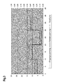
- Figure 3 shows on the probe or on the sensor 107, the voltage curve, which results using a corresponding buck converter and an indirect control of the lambda probe 102 with the supply voltage U in in the amount of 24V. It can be seen that the probe voltage U out no longer goes back to zero.
- the control of the lambda probe 102 and the probe heater 104 is carried out here not with a pulsed supply voltage, but with a steady DC voltage. This results in a more uniform current distribution and a more even or gentle probe operation.
- the supply of the probe 102 and the probe heater 104, respectively, can also take place with a voltage higher than the maximum allowable probe voltage through the use of the corresponding conversion measure (i.e., the buck converter 109).
- the internal resistance of the sensor part of the lambda probe depends on a probe internal temperature.
- the probe is preferably used to evaluate the oxygen content at a constant temperature, i. at a correspondingly constant operating point, held.
- This temperature may e.g. be specified by the probe manufacturer.
- the temperature value corresponds to a fixed nominal value of the internal resistance.
- the microprocessor cyclically detects the actual internal resistance of the probe, using the probe interface module. This value serves as the input to the (e.g., digital) PI controller, which has the task of constantly controlling the probe temperature.
- the (e.g., digital) PI controller which has the task of constantly controlling the probe temperature.
- the novel drive option presented here provides for a buck converter to be operated at a fixed operating frequency (for example in a range from 20 kHz to 150 kHz).
- the actuating signal (duty cycle) is used to set the analog output voltage of the buck converter.
- the temperature control is relatively slow. Therefore, it is sufficient to use the PI controller e.g. operate according to a 100Hz raster and determine the buck converter, e.g. to drive with a frequency of 80kHz.
- the duty cycle (duty cycle), for example, only every 10ms readjusted. In between, i. during the further 80kHz cycles, the set duty cycle works.
- the maximum heating voltage can be additionally monitored by means of an A / D converter to ensure that the sensor does not see more than the permissible voltage Umax (see monitoring device 207 in Fig.2 ).
- another sensor can also be controlled on the sensor module, so that the use as a general sensor module can be realized.
- Household appliances in particular cooking appliance 102 Lambda probe 103 sensor 104 probe heating 105 control 106 interface 107 sensors 108 first line for a supply voltage U in 109 down converter 110 Dimensions 111 Cable for probe heating 112 Signal or data line 113 switch 114 Inductance, in particular coil 115 diode 116 Capacity, in particular capacitor 117 switching signal 118 node 201 sensor device 202 sensor line 203 measurand 204 Signal processing device 205 Control device for buckets 206 Control line to the buck converter 207 monitoring device 208 second line for a supply voltage Ux f Frequency as switching frequency t on duty T period U Bat Battery voltage, in particular 12 V U in first supply voltage U out probe voltage Ux second supply voltage
Landscapes
- Engineering & Computer Science (AREA)
- Chemical & Material Sciences (AREA)
- Combustion & Propulsion (AREA)
- Mechanical Engineering (AREA)
- General Engineering & Computer Science (AREA)
- Combined Controls Of Internal Combustion Engines (AREA)
- General Preparation And Processing Of Foods (AREA)
Abstract
Description
- Die Erfindung betrifft vorrichtungsgemäß ein Haushaltsgerät mit einer Lambda-Sonde. Verfahrensgemäß betrifft die Erfindung ein Verfahren zum Betreiben eines Haushaltsgeräts mit einer Lambda-Sonde.
- Im KFZ- und LKW-Bereich werden Lambda-Sonden zur Optimierung einer Treibstoffverbrennung im Motor abhängig vom Sauerstoffgehalt verwendet. Lambda-Sonden weisen ein Heizelement als Sondenheizung auf. Beim Betrieb einer solchen Lambda-Sonde wird deren Heizelement direkt mit einer 12V-Versorgung, im KFZ-Bereich üblicherweise der Batteriespannung, verbunden und über ein entsprechendes Steuerelement, zum Beispiel mit einer festen Betriebs-Frequenz (z.B. f = 100Hz) und einem variablen Tastverhältnis gepulst angesteuert. Umgesetzt wird so eine direkte Ansteuerung der Lambda-Sondenheizung mit der Batteriespannung von 12V.
- Dabei wird durch das gepulste Schalten mit Hilfe der Einschaltdauer ton pro Zyklus bzw. Periodendauer T die effektive Spannung Ueff am Heizelement beeinflusst bzw. eingestellt. Berechnen lässt sich die effektive Spannung Ueff gemäß:

- Diese Art der Ansteuerung hat zur Folge, dass in der Zeit während der Einschaltdauer ton der Maximalwert UBat am Heizelement der Sonde anliegt und in dieser Zeit ein entsprechend großer Heizstrom mit großen Spitzenwerten fließt.
- Es ist die Aufgabe der vorliegenden Erfindung, ein Haushaltsgerät mit einer Lambda-Sonde mit einem einfacheren Aufbau bereitzustellen. Insbesondere sollen herkömmliche Lambda-Sonden in dem Haushaltsgerät einsetzbar sein.
- Diese Aufgabe wird gemäß den Merkmalen der unabhängigen Ansprüche gelöst. Bevorzugte Ausführungsformen sind insbesondere den abhängigen Ansprüchen entnehmbar.
- Zur Lösung der Aufgabe wird ein Haushaltsgerät mit einer Lambda-Sonde vorgeschlagen, wobei der Lambda-Sonde ein Tiefsetzer vorgeschaltet ist oder die Lambda-Sonde einen Tiefsetzer aufweist.
- Dadurch kann eine insbesondere handelsübliche Lambda-Sonde mit einer vorbestimmten Betriebsspannung dennoch an einer höheren Versorgungsspannung betrieben werden, z.B. für den Fall, dass das Haushaltsgerät nur eine solche höhere Versorgungsspannung bereitstellt. Durch den Tiefsetzer (auch bezeichnet als Abwärtswandler, Step-Down-Konverter oder Buck-Konverter) kann eine passende Spannung zum Betrieb der Lambdasonde, insbesondere der Heizung der Lambdasonde, aus einer höheren Spannung konvertiert werden.
- Dabei ist gemäß der ersten Ausgestaltung der Tiefsetzer in einem Bereich zwischen beispielsweise einem Gehäuse der Lambda-Sonde und einem Netzspannungsanschluss innerhalb des Haushaltsgeräts angeordnet. Gemäß der zweiten Ausgestaltung ist der Tiefsetzer insbesondere in einem Gehäuse angeordnet, welches die Lambda-Sonde aufnimmt, oder der Lambda-Sonde funktionell zugeordnet. Anstatt des Netzspannungsanschlusses kann auch eine Gleichspannung verwendet werden, z.B. in Höhe von 24Volt.
- Das Gargerät kann insbesondere ein Kochfeld, einen Ofen (Backofen und/oder Mikrowellenofen), einen Dampfgarer oder einen Vakuumgarer umfassen.
- Es ist eine Weiterbildung, dass das Haushaltsgerät mit einer Sensorik ausgestattet ist, wobei die Sensorik der Lambda-Sonde oder mindestens einer Komponente der Lambda-Sonde vorgeschaltet ist und wobei die Sensorik den Tiefsetzer aufweist.
- Gemäß einer Ausgestaltung ist die Sensorik als Ansteuerungselektronik der Lambda-Sonde ausgebildet.
- Die Besonderheit der verwendeten Spannungskonvertierung ist in diesem Fall gemäß einer Ausgestaltung, dass die Konvertierung nicht bereits im zentralen Netzteil des Backofens stattfindet, sondern dezentral im Tiefsetzer auf der Ansteuerelektronik der Lambda-Sonde. Entsprechend wird die Ansteuerelektronik der Lambda-Sonde wie auch andere Komponenten des Haushaltsgeräts ebenfalls mit einer höheren Spannung (z.B. 24V), die im Backofen oder sonstigem Gargerät als beispielhaftem Haushaltsgerät für andere Verbraucher bereits vorliegt, versorgt.
- Es ist eine andere Weiterbildung, dass eine Ausgangsspannung des Tiefsetzers als eine Sondenspannung an eine Sondenheizung der Lambda-Sonde angelegt ist.
- Eine andere Weiterbildung ist es, dass ein Schalter des Tiefsetzers (109) mit einer Frequenz, die in einem Bereich zwischen 20kHz und 150kHz liegt, ansteuerbar ist.
- So kann eine Steuer- oder Regeleinrichtung des Tiefsetzers vorgesehen sein, die ein Schaltsignal mit einer derartigen Frequenz einem Schalter des Tiefsetzers bereitstellt. Insbesondere kann der Tiefsetzer mindestens einen Schalter aufweisen, der mit einer solchen Frequenz ansteuerbar ist.
- Gemäß einer zusätzlichen Weiterbildung ist der Tiefsetzer als ein SEPIC- oder als ein Ćuk-Wandler ausgeführt.
- Auch ist es eine Weiterbildung, dass der Tiefsetzer in einem kontinuierlichen Übertragungsmodus (CCM = Continuous Conduction Mode) betrieben wird.
- Mit Hilfe eines auf dem Modul platzierten Tiefsetzers in Ausgestaltung als insbesondere Tiefsetzer in einer Betriebsart mit einem "kontinuierlich fließenden" Strom wird die Heizsonden-Versorgungsspannung in Form einer stetigen Gleichspannung generiert, wobei die erzeugte bzw. bereitgestellte (konvertierte) Gleichspannung die maximal zulässige Spannung der Lambdasonde zu keinem Zeitpunkt übersteigt.
- Eine nächste Weiterbildung besteht darin, dass das Haushaltsgerät als ein Gargerät ausgebildet ist und an einer Steuerung zum Steuern einer Garautomatik, insbesondere Backautomatik, zumindest eine Messgröße oder daraus abgeleitete Größe eines Sensors der Lambda-Sonde anliegt.
- Dies ermöglicht beispielsweise eine vom Feuchtegehalt abhängige Bestimmung, wann ein Gargut oder Backgut fertig ist. Anstelle einer bislang zeitabhängigen Steuerung von Garprogrammen kann dadurch eine automatisierte Steuerung abhängig vom tatsächlichen Zustand des Garguts vorgenommen werden.
- Die vorstehende Aufgabe wird auch gelöst durch ein Verfahren zum Betreiben einer Lambda-Sonde eines Haushaltsgeräts, insbesondere Gargeräts, bei dem zumindest eine Komponente der Lambda-Sonde mittels eines Tiefsetzers betrieben wird.
- Unter dem Betreiben wird insbesondere ein Versorgen einer solchen Komponente mit einer Betriebsspannung, ein Ansteuern einer Funktionalität der Sonde oder einer Sensorik der Sonde selber oder auch ein Bereitstellen von Messgrößen oder daraus abgeleiteten Parametern für andere Komponenten des Haushaltsgeräts verstanden.
- Es ist auch eine Weiterbildung, dass mindestens ein Parameter der Lambda-Sonde gemessen wird.
- Ein solcher Parameter ist insbesondere eine Messgröße, die einen Sauerstoffgehalt der Umgebung der Sonde repräsentiert.
- Es ist noch eine Weiterbildung, dass das Haushaltsgerät mittels des mindestens einen Parameters angesteuert wird. Eine weitere Weiterbildung besteht darin, dass der Tiefsetzer mit einer Frequenz angesteuert wird, die zwischen 20kHz und 150kHz liegt.
- Ermöglicht wird insbesondere der Einsatz handelsüblicher Lambda-Sonden, wie sie im KFZ- und LKW-Bereich eingesetzt werden, auch in einem Haushaltsgerät mit davon abweichender Spannungsversorgung. Eine Spannungsversorgung z.B. in Höhe von 12V stellt die Versorgung der Heizung der Lambdasonde (Sondenheizung) sicher. Neben einer 24V- und einer 5V-Versorgung, wie sie im Gargerät insbesondere zur Verfügung stehen, wird die 12V-Versorgung mittels des Tiefsetzers erreicht. Dies ist auch von Vorteil, wenn z.B. keine weitere Elektronikbaugruppe im Backofen eine 12V-Versorgung benötigt.
- Weitere Vorteile insbesondere gegenüber bisher Bekanntem sind:
- Es ist keine separate 12V-Versorgung der Lambda-Sonde nötig, die Versorgung erfolgt anhand der höheren in dem Haushaltsgerät verfügbaren Spannung mittels des hier genannten Tiefsetzers.
- Stromspitzen werden reduziert, da die sich der Strom über die gesamte Einschaltdauer besser verteilt.
- Die Sondenheizung wird gleichmäßig belastet, da die Sondenspannung dauerhaft und nicht als getaktetes Signal an der Sonde anliegt.
- Ein Übersprechen der Sondenheizung auf das Sensorteil der Sonde wird minimiert aufgrund des kontinuierlichen Stromflusses in der Sondenheizung.
- In den folgenden Figuren wird die Erfindung anhand eines Ausführungsbeispiels schematisch genauer beschrieben. Dabei können zur Übersichtlichkeit gleiche oder gleichwirkende Elemente mit gleichen Bezugszeichen versehen sein.
- Fig.1
- zeigt ein Gargerät und eine daran angeschlossene Sensorik mit einer Lambda-Sonde.
- Fig.2
- zeigt eine solche Sensorik mit zusätzlichen Komponenten.
- Fig.3
- zeigt ein Diagramm mit über einen zeitlichen Verlauf verschiedenen Spannungsverläufen.
-
Fig.1 zeigt einen Ausschnitt eines beispielhaften Gargeräts 101 und eine daran angeschlossene Lambda-Sonde 102. Die Lambda-Sonde 102 weist einen Sensor 103 und eine Sondenheizung 104 auf. Die Lambda-Sonde 102 ist an eine Steuerung 105 des Gargeräts 101 über eine Schnittstelle 106 angeschlossen. Die Lambdasonde 102 ist beispielhaft Teil einer Sensorik 107. Die Sensorik 107 kann außerhalb des Gargeräts 101 angeordnet oder als Teil des Gargeräts 101 ausgeführt sein. - Über die Schnittstelle 106 ist eine Leitung 108 mit einem Tiefsetzer 109 der Sensorik 107 verbunden. Auf der Leitung 108 liegt gegenüber Masse 110 eine Versorgungsspannung Uin in Höhe von beispielsweise 24V an. Insbesondere ist auch der Masseanschluss über eine Leitung mit der Schnittstelle 106 und der Masse des Gargeräts verbunden.
- Der Tiefsetzer 109 dient dazu, die Versorgungsspannung Uin auf eine Sondenspannung Uout, z.B. 12V, zum Betrieb der Sondenheizung 104 zu konvertieren. Von dem Tiefsetzer 109 wird die Sondenspannung Uout über eine Leitung 111 der Sondenheizung 104 bereitgestellt, deren weiterer Anschluss mit Masse 110 verbunden ist.
- Die Sensorik 107 ist außerdem über eine Signal- oder Datenleitung 112 mit der Schnittstelle 106 bzw. der Steuerung 105 verbunden, um über die Signal- oder Datenleitung 112 Daten oder Signale, die auf einer Messgröße des Sensors 103 beruhen, zu übertragen.
- Der Tiefsetzer 109 umfasst einen Schalter 113, der in Reihe mit einer Spule 114 geschaltet ist, wobei zwischen dem Schalter 113 und der Spule 114 ein Knoten 118 angeordnet ist. Der Knoten 118 ist mit der Kathode einer Diode 115 verbunden, die Anode der Diode ist mit Masse 110 verbunden. Parallel zu dem Ausgang des Tiefsetzers ist ein Kondensator 116 angeordnet. Der Ausgang des Tiefsetzers 109 ist mit der Sondenheizung 104 verbunden.
- Der Schalter 113 wird mit einem Schaltsignal 117 mit einer Schaltfrequenz f angesteuert. Durch die Dimensionierung des Tiefsetzers 109 in Verbindung mit dem Schaltsignal 117 ergibt sich eine entsprechende Konvertierung der eingehenden Spannung Uin in die ausgehende Spannung Uout, die zum Betrieb der Lamdbasonde 102, insbesondere der Sondenheizung 104, benötigt wird.
- Ermöglicht wird so die Verwendung einer Versorgungsspannung Uout in Höhe von 24V, die größer als eine maximal zulässige Sondenspannung (z.B. 16,5V) ist. Der Tiefsetzer 109 verhindert, dass ein zu hoher Spannungswert an der Lambdasonde 102 anliegt und diese beschädigt.
-
Fig.2 zeigt eine schematische Darstellung der Sensorik 107 mit einer Sensorikeinrichtung 201, die der Lambdasonde 102 vorgeschaltet ist. - Die Sensorikeinrichtung 201 umfasst den Tiefsetzer 109. Die Leitung 108 für die Versorgungsspannung Uin führt in die Sensorikeinrichtung 201 und liegt wieder am Tiefsetzer 109 an, der über die Leitung 111 mit der Sondenheizung 104 verbunden ist. Die Sondenheizung 104 wie auch die Sensorikeinrichtung 201 sind jeweils auf Masse 110 geschaltet.
- Von dem Sensor 103 führt eine Sensorleitung 202 zur Übertragung einer Messgröße 203 des Sensors 103 in die Sensorikeinrichtung 201. Die Sensorleitung 202 ist in der Sensorikeinrichtung 201 insbesondere mit einer Signalverarbeitungseinrichtung 204 und mit einer Regeleinrichtung 205 verbunden, an welche die Messgröße 203 angelegt wird. Die Signalverarbeitungseinrichtung 204 dient zur Vorverarbeitung der Messgröße 203 und zum Ausgeben entsprechender (z.B. digitalisierter) Daten auf die Signal- oder Datenleitung 112.
- Die Regeleinrichtung 205 regelt das Schaltsignal 117 (insbesondere die Schaltfrequenz f) und legt das Schaltsignal 117 über eine Leitung 206 an den Tiefsetzer 109 bzw. an dessen Schalter 113 an. Insbesondere kann die Regeleinrichtung 205 als ein so genannter PI-Regler (d.h. ein Regler mit einem proportionalen und einen integrierenden Anteil) ausgebildet sein.
- In der Sensorikeinrichtung 201 ist insbesondere auch eine Überwachungseinrichtung 207 vorgesehen, die z.B. über einen Analog-Digital-Wandler mit der Leitung 111 zur Sondenheizung 104 verbunden ist. Die Überwachungseinrichtung 207 kann z.B. feststellen, ob die Spannung, die an die Sondenheizung 104 angelegt wird, in einem zulässigen Bereich liegt; gegebenenfalls kann die Überwachungseinrichtung 207 eine Abschaltung oder eine entsprechende Korrektur des Tiefsetzers 109 veranlassen.
- Eine zweite Leitung 208 führt von der Schnittstelle 106 zum Anlegen einer weiteren Versorgungsspannung Ux von beispielsweise 5 V zu der Sensorikeinrichtung 201. Diese weitere Versorgungsspannung Ux dient zum Versorgen von verschiedenen Komponenten der Sensorikeinrichtung 201, wie beispielsweise der Signalverarbeitungseinrichtung 204, der Regeleinrichtung 205 und der Überwachungseinrichtung 207, die insbesondere (zumindest teilweise) mittels eines Programms in einer Kontrolleinheit, z.B. einem Mikrocontroller oder Mikroprozessor, realisiert sein können.
- Ermöglicht wird auf dieser Grundlage insbesondere eine Entwicklung eines Sensormoduls für Gargeräte 101, insbesondere Herde.
- Gemäß der in
Fig.1 schematisch dargestellten Ausgestaltung erfolgt eine Versorgung der Lambda-Sonde 102 mit der ersten Versorgungsspannung Uin, die entsprechend durch den Tiefsetzer 109 auf eine zulässige Spannung herabgesetzt wird. Der Tiefsetzer 109 wird dabei mit der höheren Versorgungsspannung Uin (z.B. 24V) betrieben. Über die Einstellung des Tastverhältnisses des Tiefsetzers sowie die Dimensionierung seiner Bauteile wird die Spannung Uout für die Sondenheizung 104 eingestellt. Die Ansteuerung des Tiefsetzers erfolgt z.B. mit Hilfe eines Mikroprozessors, wobei der Schalter 113 vorzugsweise mit einer Taktfrequenz z.B. in einem Bereich zwischen 20kHz und 150kHz betrieben wird. - Über das einstellbare Tastverhältnis kann die gewünschte Ausgangsspannung des Tiefsetzers 109 eingestellt werden. Der Mikroprozessor begrenzt dabei die Einschaltdauer in dem Maße, dass zu keinem Zeitpunkt eine größere Ausgangsspannung als die maximal für die Lambdasonde 102 zulässige Spannung anliegt. Die Einschaltdauer ton bzw. die sich einstellende Ausgangs- bzw. Sondenspannung Uout ergibt sich gemäß der folgenden Beziehung:

wobei - ton
- die Einschaltdauer innerhalb einer Periode T,
- fs
- eine Schaltfrequenz mit dem der Schalter 113 betrieben wird,
- Uout
- die von dem Tiefsetzer 109 bereitgestellte Ausgangsspannung,
- Uin
- die am Eingang des Tiefsetzers 109 anliegende und herabzusetzende Eingangsspannung,
- Ufw
- eine Vorwärtsspannung der eingesetzten Diode in dem Tiefsetzer (je nach Ausführung der Diode liegt die Vorwärtsspannung typischerweise zwischen 0,3V und 0,7V).
-
Fig.3 zeigt an der Sonde bzw. an der Sensorik 107 den Spannungsverlauf, der sich unter Verwendung eines entsprechenden Tiefsetzers ergibt und eine indirekte Ansteuerung der Lambda-Sonde 102 mit der Versorgungsspannung Uin in Höhe von 24V. Erkennbar ist, dass die Sondenspannung Uout nicht mehr bis auf null zurückgeht. - Die Ansteuerung der Lambda-Sonde 102 bzw. der Sondenheizung 104 erfolgt hierbei nicht mit einer gepulsten Versorgungsspannung, sondern mit einer stetigen Gleichspannung. Dadurch ergibt sich eine gleichmäßigere Stromverteilung und ein gleichmäßigerer bzw. schonender Sondenbetrieb. Die Versorgung der Sonde 102 bzw. der Sondenheizung 104 kann durch die Verwendung der entsprechenden Konvertierungsmaßnahme (d.h. den Tiefsetzer 109) auch mit einer Spannung stattfinden, die höher als die maximal zulässige Sondenspannung ist.
- Aspekte des insbesondere verfahrenstechnischen Prinzips werden nachfolgend unter Verweis auch auf die Konfiguration gemäß
Fig.2 beschrieben. - Der Innenwiderstand des Sensorik-Teils der Lambda-Sonde (zum Beispiel einer Nernst-Zelle) ist abhängig von einer Sondeninnentemperatur.
- Die Sonde wird zur Auswertung des Sauerstoffgehalts vorzugsweise auf einer konstanten Temperatur, d.h. auf einem entsprechend konstanten Arbeitspunkt, gehalten. Diese Temperatur kann z.B. vom Sondenhersteller vorgegeben sein. Der Temperaturwert entspricht einem festen Sollwert des Innenwiderstands.
- Der Mikroprozessor erfasst zyklisch den Ist-Innenwiderstand der Sonde, mit Hilfe des Sonden-Interface-Bausteins. Dieser Wert dient als Eingangssignal des (z.B. digitalen) PI-Reglers, der die Aufgabe hat, die Sondentemperatur konstant zu regeln.
- Die hier vorgestellte neuartige Ansteuermöglichkeit sieht insbesondere vor, dass ein Tiefsetzer mit fester Arbeitsfrequenz betrieben wird (z.B. in einem Bereich von 20kHz bis 150kHz). Über das Stellsignal (Duty-Cycle) wird die analoge Ausgangsspannung des Tiefsetzers eingestellt.
- Die Temperaturregelung ist verhältnismäßig träge. Daher reicht es aus, den PI-Regler z.B. gemäß eines 100Hz-Rasters zu betreiben bzw. zu bestimmen und den Tiefsetzer z.B. mit einer Frequenz von 80kHz anzusteuern. Somit wird der Duty-Cycle ("Tastverhältnis") beispielsweise nur alle 10ms neu eingestellt. Dazwischen, d.h. während der weiteren 80kHz-Zyklen, wirkt der eingestellte Duty-Cycle.
- Optional kann die maximale Heizspannung mit Hilfe eines AD-Wandlers zusätzlich überwacht werden, damit sichergestellt wird, dass die Sonde nicht mehr als die zulässige Spannung Umax sieht (vergleiche Überwachungseinrichtung 207 in
Fig.2 ). - Auf dem Sensormodul kann z.B. auch ein weiterer Sensor mitangesteuert werden, so dass der Einsatz als ein allgemeines Sensorik-Modul realisierbar ist.
-
101 Haushaltsgeräte, insbesondere Gargerät 102 Lambda-Sonde 103 Sensor 104 Sondenheizung 105 Steuerung 106 Schnittstelle 107 Sensorik 108 erste Leitung für eine Versorgungsspannung Uin 109 Tiefsetzer 110 Masse 111 Leitung zur Sondenheizung 112 Signal- oder Datenleitung 113 Schalter 114 Induktivität, insbesondere Spule 115 Diode 116 Kapazität, insbesondere Kondensator 117 Schaltsignal 118 Knoten 201 Sensorikeinrichtung 202 Sensorleitung 203 Messgröße 204 Signalverarbeitungseinrichtung 205 Regeleinrichtung für Tiefsetzer 206 Regelleitung zum Tiefsetzer 207 Überwachungseinrichtung 208 zweite Leitung für eine Versorgungsspannung Ux f Frequenz als Schaltfrequenz ton Einschaltdauer T Periode UBat Batteriespannung, insbesondere 12 V Uin erste Versorgungsspannung Uout Sondenspannung Ux zweite Versorgungsspannung
Claims (12)
- Haushaltsgerät mit einer Lambda-Sonde (102), wobei der Lambda-Sonde (102) ein Tiefsetzer (109) vorgeschaltet ist oder die Lambda-Sonde (102) einen Tiefsetzer (109) aufweist.
- Haushaltsgerät nach Anspruch 1 mit einer Sensorik (107), die Komponenten der Lambda-Sonde (102) vorgeschaltet ist, wobei die Sensorik (107) den Tiefsetzer (109) aufweist.
- Haushaltsgerät nach einem der Ansprüche 1 oder 2, bei dem eine Ausgangsspannung des Tiefsetzers (109) als eine Sondenspannung (Uout) an eine Sondenheizung (104) der Lambda-Sonde (102) angelegt ist.
- Haushaltsgerät nach einem der vorhergehenden Ansprüche, bei dem ein Schalter des Tiefsetzers (109) mit einer Frequenz, die in einem Bereich zwischen 20kHz und 150kHz liegt, ansteuerbar ist.
- Haushaltsgerät nach einem der vorhergehenden Ansprüche, bei dem der Tiefsetzer (109) als ein SEPIC- oder als ein Ćuk-Wandler ausgeführt ist.
- Haushaltsgerät nach einem der vorhergehenden Ansprüche, bei dem der Tiefsetzer im kontinuierlichen Übertragungsmodus betrieben wird.
- Haushaltsgerät nach einem der vorhergehenden Ansprüche, wobei das Haushaltsgerät als ein Gargerät (101) ausgebildet ist und an einer Steuerung (105) zum Steuern einer Garautomatik, insbesondere Backautomatik, zumindest eine Messgröße (203) oder daraus abgeleitete Größe eines Sensors (103) der Lambda-Sonde (102) anliegt.
- Verfahren zum Betreiben einer Lambda-Sonde (102) eines Haushaltsgeräts, insbesondere Gargeräts (101), bei dem zumindest eine Komponente der Lambda-Sonde (102) mittels eines Tiefsetzers (109) betrieben wird.
- Verfahren nach Anspruch 8, bei dem mindestens ein Parameter der Lambda-Sonde (102) gemessen wird.
- Verfahren nach einem der Ansprüche 8 oder 9, bei dem das Haushaltsgerät mittels des mindestens einen Parameters angesteuert wird.
- Verfahren nach einem der Ansprüche 8 bis 10, bei dem der Tiefsetzer mit einer Frequenz angesteuert wird, die zwischen 20kHz und 150kHz liegt.
- Verfahren nach einem der Ansprüche 8 bis 11 zur Durchführung in einem Haushaltsgerät nach einem der Ansprüche 1 bis 7.
Priority Applications (1)
| Application Number | Priority Date | Filing Date | Title |
|---|---|---|---|
| PL13157931T PL2639512T3 (pl) | 2012-03-16 | 2013-03-06 | Urządzenie gospodarstwa domowego z sondą lambda lub sposób użytkowania urządzenia gospodarstwa domowego z sondą lambda |
Applications Claiming Priority (1)
| Application Number | Priority Date | Filing Date | Title |
|---|---|---|---|
| DE102012204224A DE102012204224A1 (de) | 2012-03-16 | 2012-03-16 | Haushaltsgerät mit einer Lambda-Sonde bzw. Verfahren zum Betreiben eines Haushaltsgeräts mit einer Lambda-Sonde |
Publications (3)
| Publication Number | Publication Date |
|---|---|
| EP2639512A2 true EP2639512A2 (de) | 2013-09-18 |
| EP2639512A3 EP2639512A3 (de) | 2014-01-08 |
| EP2639512B1 EP2639512B1 (de) | 2020-05-06 |
Family
ID=47779984
Family Applications (1)
| Application Number | Title | Priority Date | Filing Date |
|---|---|---|---|
| EP13157931.0A Active EP2639512B1 (de) | 2012-03-16 | 2013-03-06 | Haushaltsgerät mit einer Lambda-Sonde bzw. Verfahren zum Betreiben eines Haushaltsgeräts mit einer Lambda-Sonde |
Country Status (3)
| Country | Link |
|---|---|
| EP (1) | EP2639512B1 (de) |
| DE (1) | DE102012204224A1 (de) |
| PL (1) | PL2639512T3 (de) |
Families Citing this family (2)
| Publication number | Priority date | Publication date | Assignee | Title |
|---|---|---|---|---|
| DE102024202085A1 (de) | 2024-03-06 | 2025-09-11 | BSH Hausgeräte GmbH | Verfahren zum Betreiben eines Haushaltsgerät und Haushaltsgerät |
| DE102024202083A1 (de) | 2024-03-06 | 2025-09-11 | BSH Hausgeräte GmbH | Verfahren zum Betreiben eines Haushaltsgeräts und Haushaltsgerät |
Family Cites Families (4)
| Publication number | Priority date | Publication date | Assignee | Title |
|---|---|---|---|---|
| US4954694A (en) * | 1989-01-31 | 1990-09-04 | Matsushita Electric Industrial Co., Ltd. | Cooking oven having function to automatically clean soils attached to inner walls thereof |
| DE10229026A1 (de) * | 2002-06-28 | 2004-01-22 | Robert Bosch Gmbh | Elektrische Schaltungsanordnung zum schnellen Hochheizbetrieb einer Lambdasonde einer Brennkraftmaschine, insbesondere eines Kraftfahrzeugs |
| DE102007060975A1 (de) * | 2007-12-14 | 2009-06-25 | Hanning Elektro-Werke Gmbh & Co. Kg | Antrieb |
| DE102010054607B3 (de) * | 2010-12-15 | 2012-01-12 | Rational Ag | Verfahren zum Betreiben eines Gargerätes sowie Gargerät |
-
2012
- 2012-03-16 DE DE102012204224A patent/DE102012204224A1/de not_active Withdrawn
-
2013
- 2013-03-06 PL PL13157931T patent/PL2639512T3/pl unknown
- 2013-03-06 EP EP13157931.0A patent/EP2639512B1/de active Active
Non-Patent Citations (1)
| Title |
|---|
| None |
Also Published As
| Publication number | Publication date |
|---|---|
| EP2639512B1 (de) | 2020-05-06 |
| DE102012204224A1 (de) | 2013-09-19 |
| PL2639512T3 (pl) | 2020-11-02 |
| EP2639512A3 (de) | 2014-01-08 |
Similar Documents
| Publication | Publication Date | Title |
|---|---|---|
| EP2236004B1 (de) | Induktionskochfeld mit einer mehrzahl von induktionsheizkörpern | |
| EP3560279B1 (de) | Gargerätevorrichtung | |
| EP2548409A1 (de) | Led-ansteuerung mit getakteter konstantstromquelle | |
| EP2506666B1 (de) | Gargerätevorrichtung | |
| EP2506665B1 (de) | Gargerätevorrichtung | |
| DE102013107872B3 (de) | Vorrichtung und Verfahren zum Betreiben einer Leuchtmittelanordnung | |
| EP2639512B1 (de) | Haushaltsgerät mit einer Lambda-Sonde bzw. Verfahren zum Betreiben eines Haushaltsgeräts mit einer Lambda-Sonde | |
| EP4097400A1 (de) | Schaltungsvorrichtung fuer eine versorgung eines warmwasserbereiters aus einer regenerativen energiequelle | |
| EP1732357A2 (de) | Heizvorrichtung für ein Induktionsgargerät | |
| EP2469972B1 (de) | Gargerätevorrichtung sowie Verfahren zum Steuern der Gargerätevorrichtung bei dem eine Flickerkenngrösse iterativ verkleinert wird. | |
| DE102011056865B3 (de) | Einrichtung zur Steuerung einer Heizungsumwälzpumpe und Steuerungsverfahren | |
| DE102015118453A1 (de) | Verfahren zum Betreiben einer Kochfeldeinrichtung | |
| EP3063505B1 (de) | Positionssensor für die erfassung einer lageposition eines aktuators | |
| DE112004000336T5 (de) | Betrieb einer Brennstoffzellen-Stromerzeugungsanlage mit festem Gleichstrom | |
| EP3602727B1 (de) | Haushaltsgerätevorrichtung und verfahren zum betrieb einer haushaltsgerätevorrichtung | |
| DE102009008255A1 (de) | Verfahren und Vorrichtung zum Betrieb eines Energiebordnetzes | |
| EP2246959A1 (de) | Haushaltsgerät mit einer Schaltungsanordnung und entsprechendes Verfahren | |
| DE102020117481B4 (de) | Heizeinrichtung für ein Kraftfahrzeug | |
| EP2506664B1 (de) | Gargerätevorrichtung | |
| EP4209114A1 (de) | Kochfeldzubehörvorrichtung | |
| EP3303935B1 (de) | Vorrichtung und verfahren zum steuern einer heizungs- und/oder kühlanlage | |
| EP1768461A1 (de) | Verfahren zum Erzeugen, Verarbeiten und Auswerten eines mit der Temperatur korrelierten Signals und entsprechende Vorrichtung | |
| DE102016123237A1 (de) | ELEKTRONISCHE TIEFSETZSTELLER-ANSTEUERVORRICHTUNG MIT VERBESSERTER iTHD | |
| EP1752073B1 (de) | Vorrichtung und Verfahren zum induktiven Erwärmen von mehreren mit einer leitfähigen Schicht versehenen Geschirrelementen zur Aufnahme von Speisen | |
| DE102015211943B4 (de) | PWM-Aktorsteuerung mit Pulsregelung |
Legal Events
| Date | Code | Title | Description |
|---|---|---|---|
| PUAI | Public reference made under article 153(3) epc to a published international application that has entered the european phase |
Free format text: ORIGINAL CODE: 0009012 |
|
| AK | Designated contracting states |
Kind code of ref document: A2 Designated state(s): AL AT BE BG CH CY CZ DE DK EE ES FI FR GB GR HR HU IE IS IT LI LT LU LV MC MK MT NL NO PL PT RO RS SE SI SK SM TR |
|
| AX | Request for extension of the european patent |
Extension state: BA ME |
|
| PUAL | Search report despatched |
Free format text: ORIGINAL CODE: 0009013 |
|
| AK | Designated contracting states |
Kind code of ref document: A3 Designated state(s): AL AT BE BG CH CY CZ DE DK EE ES FI FR GB GR HR HU IE IS IT LI LT LU LV MC MK MT NL NO PL PT RO RS SE SI SK SM TR |
|
| AX | Request for extension of the european patent |
Extension state: BA ME |
|
| RIC1 | Information provided on ipc code assigned before grant |
Ipc: F24C 7/08 20060101AFI20131202BHEP |
|
| 17P | Request for examination filed |
Effective date: 20140708 |
|
| RBV | Designated contracting states (corrected) |
Designated state(s): AL AT BE BG CH CY CZ DE DK EE ES FI FR GB GR HR HU IE IS IT LI LT LU LV MC MK MT NL NO PL PT RO RS SE SI SK SM TR |
|
| RAP1 | Party data changed (applicant data changed or rights of an application transferred) |
Owner name: BSH HAUSGERAETE GMBH |
|
| 17Q | First examination report despatched |
Effective date: 20160906 |
|
| STAA | Information on the status of an ep patent application or granted ep patent |
Free format text: STATUS: EXAMINATION IS IN PROGRESS |
|
| GRAP | Despatch of communication of intention to grant a patent |
Free format text: ORIGINAL CODE: EPIDOSNIGR1 |
|
| STAA | Information on the status of an ep patent application or granted ep patent |
Free format text: STATUS: GRANT OF PATENT IS INTENDED |
|
| INTG | Intention to grant announced |
Effective date: 20191220 |
|
| GRAS | Grant fee paid |
Free format text: ORIGINAL CODE: EPIDOSNIGR3 |
|
| GRAA | (expected) grant |
Free format text: ORIGINAL CODE: 0009210 |
|
| STAA | Information on the status of an ep patent application or granted ep patent |
Free format text: STATUS: THE PATENT HAS BEEN GRANTED |
|
| AK | Designated contracting states |
Kind code of ref document: B1 Designated state(s): AL AT BE BG CH CY CZ DE DK EE ES FI FR GB GR HR HU IE IS IT LI LT LU LV MC MK MT NL NO PL PT RO RS SE SI SK SM TR |
|
| REG | Reference to a national code |
Ref country code: GB Ref legal event code: FG4D Free format text: NOT ENGLISH |
|
| REG | Reference to a national code |
Ref country code: AT Ref legal event code: REF Ref document number: 1267375 Country of ref document: AT Kind code of ref document: T Effective date: 20200515 Ref country code: CH Ref legal event code: EP |
|
| REG | Reference to a national code |
Ref country code: DE Ref legal event code: R096 Ref document number: 502013014678 Country of ref document: DE |
|
| REG | Reference to a national code |
Ref country code: IE Ref legal event code: FG4D Free format text: LANGUAGE OF EP DOCUMENT: GERMAN |
|
| REG | Reference to a national code |
Ref country code: LT Ref legal event code: MG4D |
|
| REG | Reference to a national code |
Ref country code: NL Ref legal event code: MP Effective date: 20200506 |
|
| PG25 | Lapsed in a contracting state [announced via postgrant information from national office to epo] |
Ref country code: LT Free format text: LAPSE BECAUSE OF FAILURE TO SUBMIT A TRANSLATION OF THE DESCRIPTION OR TO PAY THE FEE WITHIN THE PRESCRIBED TIME-LIMIT Effective date: 20200506 Ref country code: SE Free format text: LAPSE BECAUSE OF FAILURE TO SUBMIT A TRANSLATION OF THE DESCRIPTION OR TO PAY THE FEE WITHIN THE PRESCRIBED TIME-LIMIT Effective date: 20200506 Ref country code: PT Free format text: LAPSE BECAUSE OF FAILURE TO SUBMIT A TRANSLATION OF THE DESCRIPTION OR TO PAY THE FEE WITHIN THE PRESCRIBED TIME-LIMIT Effective date: 20200907 Ref country code: NO Free format text: LAPSE BECAUSE OF FAILURE TO SUBMIT A TRANSLATION OF THE DESCRIPTION OR TO PAY THE FEE WITHIN THE PRESCRIBED TIME-LIMIT Effective date: 20200806 Ref country code: IS Free format text: LAPSE BECAUSE OF FAILURE TO SUBMIT A TRANSLATION OF THE DESCRIPTION OR TO PAY THE FEE WITHIN THE PRESCRIBED TIME-LIMIT Effective date: 20200906 Ref country code: GR Free format text: LAPSE BECAUSE OF FAILURE TO SUBMIT A TRANSLATION OF THE DESCRIPTION OR TO PAY THE FEE WITHIN THE PRESCRIBED TIME-LIMIT Effective date: 20200807 Ref country code: FI Free format text: LAPSE BECAUSE OF FAILURE TO SUBMIT A TRANSLATION OF THE DESCRIPTION OR TO PAY THE FEE WITHIN THE PRESCRIBED TIME-LIMIT Effective date: 20200506 |
|
| PG25 | Lapsed in a contracting state [announced via postgrant information from national office to epo] |
Ref country code: HR Free format text: LAPSE BECAUSE OF FAILURE TO SUBMIT A TRANSLATION OF THE DESCRIPTION OR TO PAY THE FEE WITHIN THE PRESCRIBED TIME-LIMIT Effective date: 20200506 Ref country code: LV Free format text: LAPSE BECAUSE OF FAILURE TO SUBMIT A TRANSLATION OF THE DESCRIPTION OR TO PAY THE FEE WITHIN THE PRESCRIBED TIME-LIMIT Effective date: 20200506 Ref country code: BG Free format text: LAPSE BECAUSE OF FAILURE TO SUBMIT A TRANSLATION OF THE DESCRIPTION OR TO PAY THE FEE WITHIN THE PRESCRIBED TIME-LIMIT Effective date: 20200806 Ref country code: RS Free format text: LAPSE BECAUSE OF FAILURE TO SUBMIT A TRANSLATION OF THE DESCRIPTION OR TO PAY THE FEE WITHIN THE PRESCRIBED TIME-LIMIT Effective date: 20200506 |
|
| PG25 | Lapsed in a contracting state [announced via postgrant information from national office to epo] |
Ref country code: AL Free format text: LAPSE BECAUSE OF FAILURE TO SUBMIT A TRANSLATION OF THE DESCRIPTION OR TO PAY THE FEE WITHIN THE PRESCRIBED TIME-LIMIT Effective date: 20200506 Ref country code: NL Free format text: LAPSE BECAUSE OF FAILURE TO SUBMIT A TRANSLATION OF THE DESCRIPTION OR TO PAY THE FEE WITHIN THE PRESCRIBED TIME-LIMIT Effective date: 20200506 |
|
| PG25 | Lapsed in a contracting state [announced via postgrant information from national office to epo] |
Ref country code: RO Free format text: LAPSE BECAUSE OF FAILURE TO SUBMIT A TRANSLATION OF THE DESCRIPTION OR TO PAY THE FEE WITHIN THE PRESCRIBED TIME-LIMIT Effective date: 20200506 Ref country code: CZ Free format text: LAPSE BECAUSE OF FAILURE TO SUBMIT A TRANSLATION OF THE DESCRIPTION OR TO PAY THE FEE WITHIN THE PRESCRIBED TIME-LIMIT Effective date: 20200506 Ref country code: IT Free format text: LAPSE BECAUSE OF FAILURE TO SUBMIT A TRANSLATION OF THE DESCRIPTION OR TO PAY THE FEE WITHIN THE PRESCRIBED TIME-LIMIT Effective date: 20200506 Ref country code: SM Free format text: LAPSE BECAUSE OF FAILURE TO SUBMIT A TRANSLATION OF THE DESCRIPTION OR TO PAY THE FEE WITHIN THE PRESCRIBED TIME-LIMIT Effective date: 20200506 Ref country code: DK Free format text: LAPSE BECAUSE OF FAILURE TO SUBMIT A TRANSLATION OF THE DESCRIPTION OR TO PAY THE FEE WITHIN THE PRESCRIBED TIME-LIMIT Effective date: 20200506 Ref country code: EE Free format text: LAPSE BECAUSE OF FAILURE TO SUBMIT A TRANSLATION OF THE DESCRIPTION OR TO PAY THE FEE WITHIN THE PRESCRIBED TIME-LIMIT Effective date: 20200506 Ref country code: ES Free format text: LAPSE BECAUSE OF FAILURE TO SUBMIT A TRANSLATION OF THE DESCRIPTION OR TO PAY THE FEE WITHIN THE PRESCRIBED TIME-LIMIT Effective date: 20200506 |
|
| REG | Reference to a national code |
Ref country code: DE Ref legal event code: R097 Ref document number: 502013014678 Country of ref document: DE |
|
| PG25 | Lapsed in a contracting state [announced via postgrant information from national office to epo] |
Ref country code: SK Free format text: LAPSE BECAUSE OF FAILURE TO SUBMIT A TRANSLATION OF THE DESCRIPTION OR TO PAY THE FEE WITHIN THE PRESCRIBED TIME-LIMIT Effective date: 20200506 |
|
| PLBE | No opposition filed within time limit |
Free format text: ORIGINAL CODE: 0009261 |
|
| STAA | Information on the status of an ep patent application or granted ep patent |
Free format text: STATUS: NO OPPOSITION FILED WITHIN TIME LIMIT |
|
| 26N | No opposition filed |
Effective date: 20210209 |
|
| PG25 | Lapsed in a contracting state [announced via postgrant information from national office to epo] |
Ref country code: SI Free format text: LAPSE BECAUSE OF FAILURE TO SUBMIT A TRANSLATION OF THE DESCRIPTION OR TO PAY THE FEE WITHIN THE PRESCRIBED TIME-LIMIT Effective date: 20200506 |
|
| PG25 | Lapsed in a contracting state [announced via postgrant information from national office to epo] |
Ref country code: MC Free format text: LAPSE BECAUSE OF FAILURE TO SUBMIT A TRANSLATION OF THE DESCRIPTION OR TO PAY THE FEE WITHIN THE PRESCRIBED TIME-LIMIT Effective date: 20200506 |
|
| REG | Reference to a national code |
Ref country code: CH Ref legal event code: PL |
|
| REG | Reference to a national code |
Ref country code: BE Ref legal event code: MM Effective date: 20210331 |
|
| PG25 | Lapsed in a contracting state [announced via postgrant information from national office to epo] |
Ref country code: FR Free format text: LAPSE BECAUSE OF NON-PAYMENT OF DUE FEES Effective date: 20210331 Ref country code: IE Free format text: LAPSE BECAUSE OF NON-PAYMENT OF DUE FEES Effective date: 20210306 Ref country code: CH Free format text: LAPSE BECAUSE OF NON-PAYMENT OF DUE FEES Effective date: 20210331 Ref country code: LU Free format text: LAPSE BECAUSE OF NON-PAYMENT OF DUE FEES Effective date: 20210306 Ref country code: LI Free format text: LAPSE BECAUSE OF NON-PAYMENT OF DUE FEES Effective date: 20210331 |
|
| REG | Reference to a national code |
Ref country code: AT Ref legal event code: MM01 Ref document number: 1267375 Country of ref document: AT Kind code of ref document: T Effective date: 20210306 |
|
| PG25 | Lapsed in a contracting state [announced via postgrant information from national office to epo] |
Ref country code: BE Free format text: LAPSE BECAUSE OF NON-PAYMENT OF DUE FEES Effective date: 20210331 |
|
| PG25 | Lapsed in a contracting state [announced via postgrant information from national office to epo] |
Ref country code: AT Free format text: LAPSE BECAUSE OF NON-PAYMENT OF DUE FEES Effective date: 20210306 |
|
| REG | Reference to a national code |
Ref country code: DE Ref legal event code: R084 Ref document number: 502013014678 Country of ref document: DE |
|
| PG25 | Lapsed in a contracting state [announced via postgrant information from national office to epo] |
Ref country code: HU Free format text: LAPSE BECAUSE OF FAILURE TO SUBMIT A TRANSLATION OF THE DESCRIPTION OR TO PAY THE FEE WITHIN THE PRESCRIBED TIME-LIMIT; INVALID AB INITIO Effective date: 20130306 |
|
| PG25 | Lapsed in a contracting state [announced via postgrant information from national office to epo] |
Ref country code: CY Free format text: LAPSE BECAUSE OF FAILURE TO SUBMIT A TRANSLATION OF THE DESCRIPTION OR TO PAY THE FEE WITHIN THE PRESCRIBED TIME-LIMIT Effective date: 20200506 |
|
| PG25 | Lapsed in a contracting state [announced via postgrant information from national office to epo] |
Ref country code: MK Free format text: LAPSE BECAUSE OF FAILURE TO SUBMIT A TRANSLATION OF THE DESCRIPTION OR TO PAY THE FEE WITHIN THE PRESCRIBED TIME-LIMIT Effective date: 20200506 |
|
| PG25 | Lapsed in a contracting state [announced via postgrant information from national office to epo] |
Ref country code: MT Free format text: LAPSE BECAUSE OF FAILURE TO SUBMIT A TRANSLATION OF THE DESCRIPTION OR TO PAY THE FEE WITHIN THE PRESCRIBED TIME-LIMIT Effective date: 20200506 |
|
| PGFP | Annual fee paid to national office [announced via postgrant information from national office to epo] |
Ref country code: GB Payment date: 20260324 Year of fee payment: 14 |
|
| PGFP | Annual fee paid to national office [announced via postgrant information from national office to epo] |
Ref country code: DE Payment date: 20260331 Year of fee payment: 14 |
|
| PGFP | Annual fee paid to national office [announced via postgrant information from national office to epo] |
Ref country code: TR Payment date: 20260227 Year of fee payment: 14 |
|
| PGFP | Annual fee paid to national office [announced via postgrant information from national office to epo] |
Ref country code: PL Payment date: 20260227 Year of fee payment: 14 |