EP2639512A2 - Appareil ménager avec une sonde lambda ou procédé de fonctionnement d'un appareil ménager avec une sonde lambda - Google Patents
Appareil ménager avec une sonde lambda ou procédé de fonctionnement d'un appareil ménager avec une sonde lambda Download PDFInfo
- Publication number
- EP2639512A2 EP2639512A2 EP13157931.0A EP13157931A EP2639512A2 EP 2639512 A2 EP2639512 A2 EP 2639512A2 EP 13157931 A EP13157931 A EP 13157931A EP 2639512 A2 EP2639512 A2 EP 2639512A2
- Authority
- EP
- European Patent Office
- Prior art keywords
- probe
- lambda probe
- voltage
- buck converter
- sensor
- Prior art date
- Legal status (The legal status is an assumption and is not a legal conclusion. Google has not performed a legal analysis and makes no representation as to the accuracy of the status listed.)
- Granted
Links
Images


Classifications
-
- F—MECHANICAL ENGINEERING; LIGHTING; HEATING; WEAPONS; BLASTING
- F24—HEATING; RANGES; VENTILATING
- F24C—DOMESTIC STOVES OR RANGES ; DETAILS OF DOMESTIC STOVES OR RANGES, OF GENERAL APPLICATION
- F24C7/00—Stoves or ranges heated by electric energy
- F24C7/08—Arrangement or mounting of control or safety devices
- F24C7/082—Arrangement or mounting of control or safety devices on ranges, e.g. control panels, illumination
- F24C7/085—Arrangement or mounting of control or safety devices on ranges, e.g. control panels, illumination on baking ovens
Definitions
- the invention relates apparatus according to a household appliance with a lambda probe. According to the invention, the invention relates to a method for operating a household appliance with a lambda probe.
- Lambda probes are used in the motor vehicle and truck sector to optimize fuel combustion in the engine depending on the oxygen content.
- Lambda probes have a heating element as probe heating.
- the effective voltage U eff on the heating element is influenced or set by the pulsed switching with the aid of the switch-on duration t on per cycle or period T.
- the maximum value U Bat is applied to the heating element of the probe during the on-time t on, and a correspondingly large heating current with large peak values flows during this time.
- a household appliance with a lambda probe wherein the lambda probe is preceded by a buck converter or the lambda probe has a buck converter.
- a particular commercially available lambda probe with a predetermined operating voltage can nevertheless be operated at a higher supply voltage, e.g. in the event that the household appliance provides only such a higher supply voltage.
- the buck converter also referred to as a buck converter, step-down converter or buck converter
- a suitable voltage for operating the lambda probe, in particular the heating of the lambda probe can be converted from a higher voltage.
- the buck converter is arranged in a region between, for example, a housing of the lambda probe and a mains voltage connection within the household appliance.
- the buck converter is arranged in particular in a housing which receives the lambda probe, or assigned to the lambda probe functionally.
- a DC voltage can also be used, e.g. in the amount of 24 volts.
- the cooking appliance may comprise a hob, an oven (oven and / or microwave oven), a steamer or a vacuum cooker.
- the household appliance is equipped with a sensor, wherein the sensor of the lambda probe or at least one component of the lambda probe is connected upstream and wherein the sensor comprises the buck converter.
- the sensor system is designed as control electronics of the lambda probe.
- the peculiarity of the voltage conversion used is in this case according to an embodiment that the conversion does not already take place in the central power supply of the oven, but decentralized in the buck converter on the control electronics of the lambda probe. Accordingly, the control electronics of the lambda probe as well as other components of the household appliance also with a higher voltage (eg 24V), which already exists in the oven or other cooking appliance as an exemplary home appliance for other consumers supplied.
- a higher voltage eg 24V
- an output voltage of the buck converter is applied as a probe voltage to a probe heater of the lambda probe.
- a control or regulating device of the buck converter which provides a switching signal with such a frequency to a switch of the buck converter.
- the buck converter may have at least one switch which can be driven with such a frequency.
- the buck converter is designed as a SEPIC or as a uc-converter.
- CCM Continuous Conduction Mode
- the household appliance is designed as a cooking appliance and is applied to a controller for controlling a cooking automatic, in particular back-up, at least one measured variable or derived therefrom size of a sensor of the lambda probe.
- the above object is also achieved by a method for operating a lambda probe of a household appliance, in particular cooking appliance, in which at least one component of the lambda probe is operated by means of a step-down converter.
- the operation is understood to mean, in particular, supplying such a component with an operating voltage, triggering a functionality of the probe or a sensor system of the probe itself or else providing measured variables or parameters derived therefrom for other components of the household appliance.
- Such a parameter is, in particular, a measured variable which represents an oxygen content of the surroundings of the probe.
- the household appliance is controlled by means of the at least one parameter.
- the buck converter is driven with a frequency which is between 20 kHz and 150 kHz.
- lambda probes such as those used in the motor vehicle and truck sector
- a power supply e.g. in the amount of 12V ensures the supply of the heating of the lambda probe (probe heating).
- the 12V supply is achieved by means of the buck converter. This is also advantageous when e.g. no other electronic assembly in the oven needs a 12V supply.
- Fig.1 shows a section of an exemplary cooking appliance 101 and a lambda probe 102 connected thereto.
- the lambda probe 102 has a sensor 103 and a probe heater 104.
- the lambda probe 102 is connected to a controller 105 of the cooking appliance 101 via an interface 106.
- the lambda probe 102 is an example of part of a sensor 107.
- the sensor 107 may be arranged outside of the cooking appliance 101 or designed as part of the cooking appliance 101.
- a line 108 is connected to a buck converter 109 of the sensor 107.
- line 108 is located relative to ground 110 a supply voltage U in of, for example, to 24V.
- the ground terminal is connected via a line to the interface 106 and the mass of the cooking appliance.
- the buck converter 109 serves to convert the supply voltage U in to a probe voltage U out , for example 12 V, for operating the probe heater 104.
- the step-down converter 109 supplies the probe voltage U out via a line 111 of the probe heater 104, whose further connection is connected to ground 110.
- the sensor 107 is also connected via a signal or data line 112 to the interface 106 and the controller 105, via the signal or Data line 112 to transmit data or signals based on a measurand of the sensor 103.
- the buck converter 109 comprises a switch 113 which is connected in series with a coil 114, wherein a node 118 is arranged between the switch 113 and the coil 114.
- the node 118 is connected to the cathode of a diode 115, the anode of the diode is connected to ground 110.
- a capacitor 116 is arranged.
- the output of the buck converter 109 is connected to the probe heater 104.
- the switch 113 is driven by a switching signal 117 having a switching frequency f.
- the dimensioning of the buck converter 109 in conjunction with the switching signal 117 results in a corresponding conversion of the incoming voltage U in into the outgoing voltage U out , which is needed to operate the lambda probe 102, in particular the probe heater 104.
- the buck converter 109 prevents an excessively high voltage value from being applied to the lambda probe 102 and damaging it.
- Fig.2 shows a schematic representation of the sensor 107 with a sensor device 201, which is connected upstream of the lambda probe 102.
- the sensor device 201 comprises the step-down converter 109.
- the line 108 for the supply voltage U in leads into the sensor device 201 and again lies against the step-down converter 109, which is connected via the line 111 to the probe heater 104.
- the probe heater 104 as well as the sensor device 201 are each connected to ground 110.
- a sensor line 202 leads to the transmission of a measured variable 203 of the sensor 103 into the sensor device 201.
- the sensor line 202 is connected in the sensor device 201 in particular to a signal processing device 204 and to a control device 205 to which the measured variable 203 is applied.
- the signal processing device 204 is used for preprocessing the measured variable 203 and outputting corresponding (eg digitized) data onto the signal or data line 112.
- the regulating device 205 regulates the switching signal 117 (in particular the switching frequency f) and applies the switching signal 117 via a line 206 to the buck converter 109 or to its switch 113.
- the controller 205 may be configured as a so-called PI controller (i.e., a regulator having a proportional and an integrating portion).
- a monitoring device 207 is provided in the sensor device 201, which may be e.g. is connected via an analog-to-digital converter with the line 111 to the probe heater 104.
- the monitor 207 may be e.g. determine whether the voltage applied to the probe heater 104 is within an allowable range; if necessary, the monitoring device 207 can initiate a shutdown or a corresponding correction of the buck converter 109.
- a second line 208 leads from the interface 106 to the application of a further supply voltage Ux, for example, 5 V to the sensor device 201.
- This further supply voltage Ux is used to supply various components of the sensor device 201, such as the signal processing device 204, the controller 205 and the monitoring device 207, in particular (at least partially) by means of a program in a control unit, eg a microcontroller or microprocessor can be realized.
- a supply of the lambda probe 102 with the first supply voltage U in which is correspondingly reduced by the buck converter 109 to an allowable voltage.
- the buck converter 109 is operated with the higher supply voltage U in (eg 24V).
- U in eg 24V
- the voltage U out for the probe heater 104 is set.
- the triggering of the buck converter is done, for example, with the aid of a microprocessor, the switch 113 is preferably operated at a clock frequency, for example in a range between 20kHz and 150kHz.
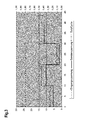
- Figure 3 shows on the probe or on the sensor 107, the voltage curve, which results using a corresponding buck converter and an indirect control of the lambda probe 102 with the supply voltage U in in the amount of 24V. It can be seen that the probe voltage U out no longer goes back to zero.
- the control of the lambda probe 102 and the probe heater 104 is carried out here not with a pulsed supply voltage, but with a steady DC voltage. This results in a more uniform current distribution and a more even or gentle probe operation.
- the supply of the probe 102 and the probe heater 104, respectively, can also take place with a voltage higher than the maximum allowable probe voltage through the use of the corresponding conversion measure (i.e., the buck converter 109).
- the internal resistance of the sensor part of the lambda probe depends on a probe internal temperature.
- the probe is preferably used to evaluate the oxygen content at a constant temperature, i. at a correspondingly constant operating point, held.
- This temperature may e.g. be specified by the probe manufacturer.
- the temperature value corresponds to a fixed nominal value of the internal resistance.
- the microprocessor cyclically detects the actual internal resistance of the probe, using the probe interface module. This value serves as the input to the (e.g., digital) PI controller, which has the task of constantly controlling the probe temperature.
- the (e.g., digital) PI controller which has the task of constantly controlling the probe temperature.
- the novel drive option presented here provides for a buck converter to be operated at a fixed operating frequency (for example in a range from 20 kHz to 150 kHz).
- the actuating signal (duty cycle) is used to set the analog output voltage of the buck converter.
- the temperature control is relatively slow. Therefore, it is sufficient to use the PI controller e.g. operate according to a 100Hz raster and determine the buck converter, e.g. to drive with a frequency of 80kHz.
- the duty cycle (duty cycle), for example, only every 10ms readjusted. In between, i. during the further 80kHz cycles, the set duty cycle works.
- the maximum heating voltage can be additionally monitored by means of an A / D converter to ensure that the sensor does not see more than the permissible voltage Umax (see monitoring device 207 in Fig.2 ).
- another sensor can also be controlled on the sensor module, so that the use as a general sensor module can be realized.
- Household appliances in particular cooking appliance 102 Lambda probe 103 sensor 104 probe heating 105 control 106 interface 107 sensors 108 first line for a supply voltage U in 109 down converter 110 Dimensions 111 Cable for probe heating 112 Signal or data line 113 switch 114 Inductance, in particular coil 115 diode 116 Capacity, in particular capacitor 117 switching signal 118 node 201 sensor device 202 sensor line 203 measurand 204 Signal processing device 205 Control device for buckets 206 Control line to the buck converter 207 monitoring device 208 second line for a supply voltage Ux f Frequency as switching frequency t on duty T period U Bat Battery voltage, in particular 12 V U in first supply voltage U out probe voltage Ux second supply voltage
Landscapes
- Engineering & Computer Science (AREA)
- Chemical & Material Sciences (AREA)
- Combustion & Propulsion (AREA)
- Mechanical Engineering (AREA)
- General Engineering & Computer Science (AREA)
- Combined Controls Of Internal Combustion Engines (AREA)
- General Preparation And Processing Of Foods (AREA)
Priority Applications (1)
| Application Number | Priority Date | Filing Date | Title |
|---|---|---|---|
| PL13157931T PL2639512T3 (pl) | 2012-03-16 | 2013-03-06 | Urządzenie gospodarstwa domowego z sondą lambda lub sposób użytkowania urządzenia gospodarstwa domowego z sondą lambda |
Applications Claiming Priority (1)
| Application Number | Priority Date | Filing Date | Title |
|---|---|---|---|
| DE102012204224A DE102012204224A1 (de) | 2012-03-16 | 2012-03-16 | Haushaltsgerät mit einer Lambda-Sonde bzw. Verfahren zum Betreiben eines Haushaltsgeräts mit einer Lambda-Sonde |
Publications (3)
| Publication Number | Publication Date |
|---|---|
| EP2639512A2 true EP2639512A2 (fr) | 2013-09-18 |
| EP2639512A3 EP2639512A3 (fr) | 2014-01-08 |
| EP2639512B1 EP2639512B1 (fr) | 2020-05-06 |
Family
ID=47779984
Family Applications (1)
| Application Number | Title | Priority Date | Filing Date |
|---|---|---|---|
| EP13157931.0A Active EP2639512B1 (fr) | 2012-03-16 | 2013-03-06 | Appareil ménager avec une sonde lambda ou procédé de fonctionnement d'un appareil ménager avec une sonde lambda |
Country Status (3)
| Country | Link |
|---|---|
| EP (1) | EP2639512B1 (fr) |
| DE (1) | DE102012204224A1 (fr) |
| PL (1) | PL2639512T3 (fr) |
Families Citing this family (2)
| Publication number | Priority date | Publication date | Assignee | Title |
|---|---|---|---|---|
| DE102024202085A1 (de) | 2024-03-06 | 2025-09-11 | BSH Hausgeräte GmbH | Verfahren zum Betreiben eines Haushaltsgerät und Haushaltsgerät |
| DE102024202083A1 (de) | 2024-03-06 | 2025-09-11 | BSH Hausgeräte GmbH | Verfahren zum Betreiben eines Haushaltsgeräts und Haushaltsgerät |
Family Cites Families (4)
| Publication number | Priority date | Publication date | Assignee | Title |
|---|---|---|---|---|
| US4954694A (en) * | 1989-01-31 | 1990-09-04 | Matsushita Electric Industrial Co., Ltd. | Cooking oven having function to automatically clean soils attached to inner walls thereof |
| DE10229026A1 (de) * | 2002-06-28 | 2004-01-22 | Robert Bosch Gmbh | Elektrische Schaltungsanordnung zum schnellen Hochheizbetrieb einer Lambdasonde einer Brennkraftmaschine, insbesondere eines Kraftfahrzeugs |
| DE102007060975A1 (de) * | 2007-12-14 | 2009-06-25 | Hanning Elektro-Werke Gmbh & Co. Kg | Antrieb |
| DE102010054607B3 (de) * | 2010-12-15 | 2012-01-12 | Rational Ag | Verfahren zum Betreiben eines Gargerätes sowie Gargerät |
-
2012
- 2012-03-16 DE DE102012204224A patent/DE102012204224A1/de not_active Withdrawn
-
2013
- 2013-03-06 PL PL13157931T patent/PL2639512T3/pl unknown
- 2013-03-06 EP EP13157931.0A patent/EP2639512B1/fr active Active
Non-Patent Citations (1)
| Title |
|---|
| None |
Also Published As
| Publication number | Publication date |
|---|---|
| EP2639512B1 (fr) | 2020-05-06 |
| DE102012204224A1 (de) | 2013-09-19 |
| PL2639512T3 (pl) | 2020-11-02 |
| EP2639512A3 (fr) | 2014-01-08 |
Similar Documents
| Publication | Publication Date | Title |
|---|---|---|
| EP2236004B1 (fr) | Plaque de cuisson à induction munie d'une pluralité d'éléments chauffants à induction | |
| EP3560279B1 (fr) | Dispositif pour appareil de cuisson | |
| EP2548409A1 (fr) | Commande de del | |
| EP2506666B1 (fr) | Dispositif d'appareil de cuisson | |
| EP2506665B1 (fr) | Dispositif d'appareil de cuisson | |
| DE102013107872B3 (de) | Vorrichtung und Verfahren zum Betreiben einer Leuchtmittelanordnung | |
| EP2639512B1 (fr) | Appareil ménager avec une sonde lambda ou procédé de fonctionnement d'un appareil ménager avec une sonde lambda | |
| EP4097400A1 (fr) | Dispositif de circuit pour alimenter un chauffe-eau à partir d'une source d'énergie renouvelable | |
| EP1732357A2 (fr) | Dispositif de chauffage pour appareils de cuisson à induction | |
| EP2469972B1 (fr) | Dispositif d'appareil de cuisson et procédé de contrôle d'un appareil de cuisson qui diminue d'une manière itérative une caractéristique flicker. | |
| DE102011056865B3 (de) | Einrichtung zur Steuerung einer Heizungsumwälzpumpe und Steuerungsverfahren | |
| DE102015118453A1 (de) | Verfahren zum Betreiben einer Kochfeldeinrichtung | |
| EP3063505B1 (fr) | Capteur de position permettant de détecter une position d'un actionneur | |
| DE112004000336T5 (de) | Betrieb einer Brennstoffzellen-Stromerzeugungsanlage mit festem Gleichstrom | |
| EP3602727B1 (fr) | Dispositif pour appareil ménager et procédé pour faire fonctionner un dispositif pour appareil ménager | |
| DE102009008255A1 (de) | Verfahren und Vorrichtung zum Betrieb eines Energiebordnetzes | |
| EP2246959A1 (fr) | Appareil ménager doté d'un dispositif de commutation et procédé correspondant | |
| DE102020117481B4 (de) | Heizeinrichtung für ein Kraftfahrzeug | |
| EP2506664B1 (fr) | Dispositif d'appareil de cuisson | |
| EP4209114A1 (fr) | Dispositif d'accessoire de table de cuisson | |
| EP3303935B1 (fr) | Dispositif et procédé de commande d'une installation de chauffage et/ou de climatisation | |
| EP1768461A1 (fr) | Méthode pour générer, traiter et évaluer un signal en correlation avec la température, et dispositif correspondant | |
| DE102016123237A1 (de) | ELEKTRONISCHE TIEFSETZSTELLER-ANSTEUERVORRICHTUNG MIT VERBESSERTER iTHD | |
| EP1752073B1 (fr) | Dispositif et procédure de chauffage inductif de plusieurs éléments de vaisselle équipés d'une couche conductrice | |
| DE102015211943B4 (de) | PWM-Aktorsteuerung mit Pulsregelung |
Legal Events
| Date | Code | Title | Description |
|---|---|---|---|
| PUAI | Public reference made under article 153(3) epc to a published international application that has entered the european phase |
Free format text: ORIGINAL CODE: 0009012 |
|
| AK | Designated contracting states |
Kind code of ref document: A2 Designated state(s): AL AT BE BG CH CY CZ DE DK EE ES FI FR GB GR HR HU IE IS IT LI LT LU LV MC MK MT NL NO PL PT RO RS SE SI SK SM TR |
|
| AX | Request for extension of the european patent |
Extension state: BA ME |
|
| PUAL | Search report despatched |
Free format text: ORIGINAL CODE: 0009013 |
|
| AK | Designated contracting states |
Kind code of ref document: A3 Designated state(s): AL AT BE BG CH CY CZ DE DK EE ES FI FR GB GR HR HU IE IS IT LI LT LU LV MC MK MT NL NO PL PT RO RS SE SI SK SM TR |
|
| AX | Request for extension of the european patent |
Extension state: BA ME |
|
| RIC1 | Information provided on ipc code assigned before grant |
Ipc: F24C 7/08 20060101AFI20131202BHEP |
|
| 17P | Request for examination filed |
Effective date: 20140708 |
|
| RBV | Designated contracting states (corrected) |
Designated state(s): AL AT BE BG CH CY CZ DE DK EE ES FI FR GB GR HR HU IE IS IT LI LT LU LV MC MK MT NL NO PL PT RO RS SE SI SK SM TR |
|
| RAP1 | Party data changed (applicant data changed or rights of an application transferred) |
Owner name: BSH HAUSGERAETE GMBH |
|
| 17Q | First examination report despatched |
Effective date: 20160906 |
|
| STAA | Information on the status of an ep patent application or granted ep patent |
Free format text: STATUS: EXAMINATION IS IN PROGRESS |
|
| GRAP | Despatch of communication of intention to grant a patent |
Free format text: ORIGINAL CODE: EPIDOSNIGR1 |
|
| STAA | Information on the status of an ep patent application or granted ep patent |
Free format text: STATUS: GRANT OF PATENT IS INTENDED |
|
| INTG | Intention to grant announced |
Effective date: 20191220 |
|
| GRAS | Grant fee paid |
Free format text: ORIGINAL CODE: EPIDOSNIGR3 |
|
| GRAA | (expected) grant |
Free format text: ORIGINAL CODE: 0009210 |
|
| STAA | Information on the status of an ep patent application or granted ep patent |
Free format text: STATUS: THE PATENT HAS BEEN GRANTED |
|
| AK | Designated contracting states |
Kind code of ref document: B1 Designated state(s): AL AT BE BG CH CY CZ DE DK EE ES FI FR GB GR HR HU IE IS IT LI LT LU LV MC MK MT NL NO PL PT RO RS SE SI SK SM TR |
|
| REG | Reference to a national code |
Ref country code: GB Ref legal event code: FG4D Free format text: NOT ENGLISH |
|
| REG | Reference to a national code |
Ref country code: AT Ref legal event code: REF Ref document number: 1267375 Country of ref document: AT Kind code of ref document: T Effective date: 20200515 Ref country code: CH Ref legal event code: EP |
|
| REG | Reference to a national code |
Ref country code: DE Ref legal event code: R096 Ref document number: 502013014678 Country of ref document: DE |
|
| REG | Reference to a national code |
Ref country code: IE Ref legal event code: FG4D Free format text: LANGUAGE OF EP DOCUMENT: GERMAN |
|
| REG | Reference to a national code |
Ref country code: LT Ref legal event code: MG4D |
|
| REG | Reference to a national code |
Ref country code: NL Ref legal event code: MP Effective date: 20200506 |
|
| PG25 | Lapsed in a contracting state [announced via postgrant information from national office to epo] |
Ref country code: LT Free format text: LAPSE BECAUSE OF FAILURE TO SUBMIT A TRANSLATION OF THE DESCRIPTION OR TO PAY THE FEE WITHIN THE PRESCRIBED TIME-LIMIT Effective date: 20200506 Ref country code: SE Free format text: LAPSE BECAUSE OF FAILURE TO SUBMIT A TRANSLATION OF THE DESCRIPTION OR TO PAY THE FEE WITHIN THE PRESCRIBED TIME-LIMIT Effective date: 20200506 Ref country code: PT Free format text: LAPSE BECAUSE OF FAILURE TO SUBMIT A TRANSLATION OF THE DESCRIPTION OR TO PAY THE FEE WITHIN THE PRESCRIBED TIME-LIMIT Effective date: 20200907 Ref country code: NO Free format text: LAPSE BECAUSE OF FAILURE TO SUBMIT A TRANSLATION OF THE DESCRIPTION OR TO PAY THE FEE WITHIN THE PRESCRIBED TIME-LIMIT Effective date: 20200806 Ref country code: IS Free format text: LAPSE BECAUSE OF FAILURE TO SUBMIT A TRANSLATION OF THE DESCRIPTION OR TO PAY THE FEE WITHIN THE PRESCRIBED TIME-LIMIT Effective date: 20200906 Ref country code: GR Free format text: LAPSE BECAUSE OF FAILURE TO SUBMIT A TRANSLATION OF THE DESCRIPTION OR TO PAY THE FEE WITHIN THE PRESCRIBED TIME-LIMIT Effective date: 20200807 Ref country code: FI Free format text: LAPSE BECAUSE OF FAILURE TO SUBMIT A TRANSLATION OF THE DESCRIPTION OR TO PAY THE FEE WITHIN THE PRESCRIBED TIME-LIMIT Effective date: 20200506 |
|
| PG25 | Lapsed in a contracting state [announced via postgrant information from national office to epo] |
Ref country code: HR Free format text: LAPSE BECAUSE OF FAILURE TO SUBMIT A TRANSLATION OF THE DESCRIPTION OR TO PAY THE FEE WITHIN THE PRESCRIBED TIME-LIMIT Effective date: 20200506 Ref country code: LV Free format text: LAPSE BECAUSE OF FAILURE TO SUBMIT A TRANSLATION OF THE DESCRIPTION OR TO PAY THE FEE WITHIN THE PRESCRIBED TIME-LIMIT Effective date: 20200506 Ref country code: BG Free format text: LAPSE BECAUSE OF FAILURE TO SUBMIT A TRANSLATION OF THE DESCRIPTION OR TO PAY THE FEE WITHIN THE PRESCRIBED TIME-LIMIT Effective date: 20200806 Ref country code: RS Free format text: LAPSE BECAUSE OF FAILURE TO SUBMIT A TRANSLATION OF THE DESCRIPTION OR TO PAY THE FEE WITHIN THE PRESCRIBED TIME-LIMIT Effective date: 20200506 |
|
| PG25 | Lapsed in a contracting state [announced via postgrant information from national office to epo] |
Ref country code: AL Free format text: LAPSE BECAUSE OF FAILURE TO SUBMIT A TRANSLATION OF THE DESCRIPTION OR TO PAY THE FEE WITHIN THE PRESCRIBED TIME-LIMIT Effective date: 20200506 Ref country code: NL Free format text: LAPSE BECAUSE OF FAILURE TO SUBMIT A TRANSLATION OF THE DESCRIPTION OR TO PAY THE FEE WITHIN THE PRESCRIBED TIME-LIMIT Effective date: 20200506 |
|
| PG25 | Lapsed in a contracting state [announced via postgrant information from national office to epo] |
Ref country code: RO Free format text: LAPSE BECAUSE OF FAILURE TO SUBMIT A TRANSLATION OF THE DESCRIPTION OR TO PAY THE FEE WITHIN THE PRESCRIBED TIME-LIMIT Effective date: 20200506 Ref country code: CZ Free format text: LAPSE BECAUSE OF FAILURE TO SUBMIT A TRANSLATION OF THE DESCRIPTION OR TO PAY THE FEE WITHIN THE PRESCRIBED TIME-LIMIT Effective date: 20200506 Ref country code: IT Free format text: LAPSE BECAUSE OF FAILURE TO SUBMIT A TRANSLATION OF THE DESCRIPTION OR TO PAY THE FEE WITHIN THE PRESCRIBED TIME-LIMIT Effective date: 20200506 Ref country code: SM Free format text: LAPSE BECAUSE OF FAILURE TO SUBMIT A TRANSLATION OF THE DESCRIPTION OR TO PAY THE FEE WITHIN THE PRESCRIBED TIME-LIMIT Effective date: 20200506 Ref country code: DK Free format text: LAPSE BECAUSE OF FAILURE TO SUBMIT A TRANSLATION OF THE DESCRIPTION OR TO PAY THE FEE WITHIN THE PRESCRIBED TIME-LIMIT Effective date: 20200506 Ref country code: EE Free format text: LAPSE BECAUSE OF FAILURE TO SUBMIT A TRANSLATION OF THE DESCRIPTION OR TO PAY THE FEE WITHIN THE PRESCRIBED TIME-LIMIT Effective date: 20200506 Ref country code: ES Free format text: LAPSE BECAUSE OF FAILURE TO SUBMIT A TRANSLATION OF THE DESCRIPTION OR TO PAY THE FEE WITHIN THE PRESCRIBED TIME-LIMIT Effective date: 20200506 |
|
| REG | Reference to a national code |
Ref country code: DE Ref legal event code: R097 Ref document number: 502013014678 Country of ref document: DE |
|
| PG25 | Lapsed in a contracting state [announced via postgrant information from national office to epo] |
Ref country code: SK Free format text: LAPSE BECAUSE OF FAILURE TO SUBMIT A TRANSLATION OF THE DESCRIPTION OR TO PAY THE FEE WITHIN THE PRESCRIBED TIME-LIMIT Effective date: 20200506 |
|
| PLBE | No opposition filed within time limit |
Free format text: ORIGINAL CODE: 0009261 |
|
| STAA | Information on the status of an ep patent application or granted ep patent |
Free format text: STATUS: NO OPPOSITION FILED WITHIN TIME LIMIT |
|
| 26N | No opposition filed |
Effective date: 20210209 |
|
| PG25 | Lapsed in a contracting state [announced via postgrant information from national office to epo] |
Ref country code: SI Free format text: LAPSE BECAUSE OF FAILURE TO SUBMIT A TRANSLATION OF THE DESCRIPTION OR TO PAY THE FEE WITHIN THE PRESCRIBED TIME-LIMIT Effective date: 20200506 |
|
| PG25 | Lapsed in a contracting state [announced via postgrant information from national office to epo] |
Ref country code: MC Free format text: LAPSE BECAUSE OF FAILURE TO SUBMIT A TRANSLATION OF THE DESCRIPTION OR TO PAY THE FEE WITHIN THE PRESCRIBED TIME-LIMIT Effective date: 20200506 |
|
| REG | Reference to a national code |
Ref country code: CH Ref legal event code: PL |
|
| REG | Reference to a national code |
Ref country code: BE Ref legal event code: MM Effective date: 20210331 |
|
| PG25 | Lapsed in a contracting state [announced via postgrant information from national office to epo] |
Ref country code: FR Free format text: LAPSE BECAUSE OF NON-PAYMENT OF DUE FEES Effective date: 20210331 Ref country code: IE Free format text: LAPSE BECAUSE OF NON-PAYMENT OF DUE FEES Effective date: 20210306 Ref country code: CH Free format text: LAPSE BECAUSE OF NON-PAYMENT OF DUE FEES Effective date: 20210331 Ref country code: LU Free format text: LAPSE BECAUSE OF NON-PAYMENT OF DUE FEES Effective date: 20210306 Ref country code: LI Free format text: LAPSE BECAUSE OF NON-PAYMENT OF DUE FEES Effective date: 20210331 |
|
| REG | Reference to a national code |
Ref country code: AT Ref legal event code: MM01 Ref document number: 1267375 Country of ref document: AT Kind code of ref document: T Effective date: 20210306 |
|
| PG25 | Lapsed in a contracting state [announced via postgrant information from national office to epo] |
Ref country code: BE Free format text: LAPSE BECAUSE OF NON-PAYMENT OF DUE FEES Effective date: 20210331 |
|
| PG25 | Lapsed in a contracting state [announced via postgrant information from national office to epo] |
Ref country code: AT Free format text: LAPSE BECAUSE OF NON-PAYMENT OF DUE FEES Effective date: 20210306 |
|
| REG | Reference to a national code |
Ref country code: DE Ref legal event code: R084 Ref document number: 502013014678 Country of ref document: DE |
|
| PG25 | Lapsed in a contracting state [announced via postgrant information from national office to epo] |
Ref country code: HU Free format text: LAPSE BECAUSE OF FAILURE TO SUBMIT A TRANSLATION OF THE DESCRIPTION OR TO PAY THE FEE WITHIN THE PRESCRIBED TIME-LIMIT; INVALID AB INITIO Effective date: 20130306 |
|
| PG25 | Lapsed in a contracting state [announced via postgrant information from national office to epo] |
Ref country code: CY Free format text: LAPSE BECAUSE OF FAILURE TO SUBMIT A TRANSLATION OF THE DESCRIPTION OR TO PAY THE FEE WITHIN THE PRESCRIBED TIME-LIMIT Effective date: 20200506 |
|
| PG25 | Lapsed in a contracting state [announced via postgrant information from national office to epo] |
Ref country code: MK Free format text: LAPSE BECAUSE OF FAILURE TO SUBMIT A TRANSLATION OF THE DESCRIPTION OR TO PAY THE FEE WITHIN THE PRESCRIBED TIME-LIMIT Effective date: 20200506 |
|
| PG25 | Lapsed in a contracting state [announced via postgrant information from national office to epo] |
Ref country code: MT Free format text: LAPSE BECAUSE OF FAILURE TO SUBMIT A TRANSLATION OF THE DESCRIPTION OR TO PAY THE FEE WITHIN THE PRESCRIBED TIME-LIMIT Effective date: 20200506 |
|
| PGFP | Annual fee paid to national office [announced via postgrant information from national office to epo] |
Ref country code: GB Payment date: 20260324 Year of fee payment: 14 |
|
| PGFP | Annual fee paid to national office [announced via postgrant information from national office to epo] |
Ref country code: DE Payment date: 20260331 Year of fee payment: 14 |
|
| PGFP | Annual fee paid to national office [announced via postgrant information from national office to epo] |
Ref country code: TR Payment date: 20260227 Year of fee payment: 14 |
|
| PGFP | Annual fee paid to national office [announced via postgrant information from national office to epo] |
Ref country code: PL Payment date: 20260227 Year of fee payment: 14 |