EP2639921A2 - Procédé de commande pour un dispositif de stockage électrique, un dispositif pour contrôler un dispositif de stockage électrique et un système de commande pour un dispositif de stockage électrique - Google Patents
Procédé de commande pour un dispositif de stockage électrique, un dispositif pour contrôler un dispositif de stockage électrique et un système de commande pour un dispositif de stockage électrique Download PDFInfo
- Publication number
- EP2639921A2 EP2639921A2 EP13158913.7A EP13158913A EP2639921A2 EP 2639921 A2 EP2639921 A2 EP 2639921A2 EP 13158913 A EP13158913 A EP 13158913A EP 2639921 A2 EP2639921 A2 EP 2639921A2
- Authority
- EP
- European Patent Office
- Prior art keywords
- electric
- storage device
- energy
- electric storage
- power
- Prior art date
- Legal status (The legal status is an assumption and is not a legal conclusion. Google has not performed a legal analysis and makes no representation as to the accuracy of the status listed.)
- Withdrawn
Links
Images


Classifications
-
- H—ELECTRICITY
- H02—GENERATION; CONVERSION OR DISTRIBUTION OF ELECTRIC POWER
- H02J—ELECTRIC POWER NETWORKS; CIRCUIT ARRANGEMENTS OR SYSTEMS FOR SUPPLYING OR DISTRIBUTING ELECTRIC POWER; SYSTEMS FOR STORING ELECTRIC ENERGY
- H02J3/00—Circuit arrangements for AC mains or AC distribution networks
- H02J3/28—Arrangements for balancing of the load in networks by storage of energy
- H02J3/32—Arrangements for balancing of the load in networks by storage of energy using batteries or super capacitors with converting means
-
- H—ELECTRICITY
- H02—GENERATION; CONVERSION OR DISTRIBUTION OF ELECTRIC POWER
- H02J—ELECTRIC POWER NETWORKS; CIRCUIT ARRANGEMENTS OR SYSTEMS FOR SUPPLYING OR DISTRIBUTING ELECTRIC POWER; SYSTEMS FOR STORING ELECTRIC ENERGY
- H02J2103/00—Details of circuit arrangements for mains or AC distribution networks
- H02J2103/30—Simulating, planning, modelling, reliability check or computer assisted design [CAD] of electric power networks
-
- H—ELECTRICITY
- H02—GENERATION; CONVERSION OR DISTRIBUTION OF ELECTRIC POWER
- H02J—ELECTRIC POWER NETWORKS; CIRCUIT ARRANGEMENTS OR SYSTEMS FOR SUPPLYING OR DISTRIBUTING ELECTRIC POWER; SYSTEMS FOR STORING ELECTRIC ENERGY
- H02J7/00—Circuit arrangements for charging or discharging batteries or for supplying loads from batteries
- H02J7/34—Parallel operation in networks using both storage and other DC sources, e.g. providing buffering
- H02J7/345—Parallel operation in networks using both storage and other DC sources, e.g. providing buffering using capacitors as storage or buffering devices
-
- Y—GENERAL TAGGING OF NEW TECHNOLOGICAL DEVELOPMENTS; GENERAL TAGGING OF CROSS-SECTIONAL TECHNOLOGIES SPANNING OVER SEVERAL SECTIONS OF THE IPC; TECHNICAL SUBJECTS COVERED BY FORMER USPC CROSS-REFERENCE ART COLLECTIONS [XRACs] AND DIGESTS
- Y02—TECHNOLOGIES OR APPLICATIONS FOR MITIGATION OR ADAPTATION AGAINST CLIMATE CHANGE
- Y02E—REDUCTION OF GREENHOUSE GAS [GHG] EMISSIONS, RELATED TO ENERGY GENERATION, TRANSMISSION OR DISTRIBUTION
- Y02E60/00—Enabling technologies; Technologies with a potential or indirect contribution to GHG emissions mitigation
-
- Y—GENERAL TAGGING OF NEW TECHNOLOGICAL DEVELOPMENTS; GENERAL TAGGING OF CROSS-SECTIONAL TECHNOLOGIES SPANNING OVER SEVERAL SECTIONS OF THE IPC; TECHNICAL SUBJECTS COVERED BY FORMER USPC CROSS-REFERENCE ART COLLECTIONS [XRACs] AND DIGESTS
- Y04—INFORMATION OR COMMUNICATION TECHNOLOGIES HAVING AN IMPACT ON OTHER TECHNOLOGY AREAS
- Y04S—SYSTEMS INTEGRATING TECHNOLOGIES RELATED TO POWER NETWORK OPERATION, COMMUNICATION OR INFORMATION TECHNOLOGIES FOR IMPROVING THE ELECTRICAL POWER GENERATION, TRANSMISSION, DISTRIBUTION, MANAGEMENT OR USAGE, i.e. SMART GRIDS
- Y04S40/00—Systems for electrical power generation, transmission, distribution or end-user application management characterised by the use of communication or information technologies, or communication or information technology specific aspects supporting them
- Y04S40/20—Information technology specific aspects, e.g. CAD, simulation, modelling, system security
Definitions
- the present invention relates to an electric storage device control method, an electric storage device control device, and an electric storage device control system for supplying an electric energy stored in an electric storage device to a driving circuit of a load.
- the electric storage device control device is used as a device that is connected between an AC power system and the load to assist a load power.
- Japanese Unexamined Patent Publication No. 2009-232526 discloses a power conversion device that assists the load power.
- the power conversion device is constructed by a combination of a DC power assist device and an inverter device, the DC power assist device including a boost/ step-down chopper and electric storage devices, such as an electric double layer capacitor, and the power assist is performed to the load power.
- Patent Document 1 Japanese Unexam. Patent Publication No. 2009-232526
- the present invention has been devised to solve the problems described above, and an object thereof is to provide an electric storage device control method, an electric storage device control device, and an electric storage device control system for being able to perform the discharge as the power assist by a simple method.
- an electric storage device control method for supplying an electric energy stored in an electric storage device to a driving circuit of a load in addition to an electric power of an AC power system
- the electric storage device control method including the steps of: measuring a value of electric power supplied from the AC power system to the driving circuit; acquiring a waveform of a supply electric power supplied from the AC power system to the driving circuit; storing a peak assist energy in the electric storage device from a regenerative energy from the driving circuit or the AC power system, which assists a peak electric energy supplied to the load; calculating an electric power threshold, at which a peak assist discharge from the electric storage device is started, based on the waveform of the supply electric power and the stored peak assist energy; and starting the peak assist discharge from the electric storage device when the measured electric power is greater than the electric power threshold.
- the electric storage device is connected to the AC power system, and the storage step includes the step of charging a portion of the peak assist energy in the electric storage device from the AC power system before the electric energy is supplied from the AC power system to the driving circuit.
- the peak assist energy stored in the electric storage device is set smaller than the regenerative energy from the driving circuit.
- the electric storage device control method further comprising the steps of: measuring the amount of the excess energy stored in the electric storage device; determining whether the amount of the excess energy stored in the electric storage device is greater than or equal to predetermined electric energy; and supplying the excess energy from the electric storage device to the driving circuit instead of the AC power system when the amount of the excess energy stored in the electric storage device is greater than or equal to the predetermined electric energy.
- the predetermined electric energy is set such that the regenerative energy can be ensured from the driving circuit according to an electric storage capacity of the electric storage device.
- an alternating current supplied from the AC power system to the driving circuit is measured, and calculation is performed using the measured alternating current and a predetermined voltage of the AC power system.
- an output voltage and an output current of a DC circuit are measured in the step of measuring the value of the electric power, the DC circuit converting an AC voltage supplied from the AC power system provided between the AC power system and the driving circuit into a DC voltage.
- an electric storage device control device that supplies an electric energy stored in the electric storage device to a driving circuit of a load in addition to an electric power of an AC power system
- the electric storage device control device including: an electric energy measurement part that measures a value of electric power supplied from the AC power system to the driving circuit; an electric power waveform acquisition part that acquires a waveform of a supply electric power supplied from the AC power system to the driving circuit; storing a peak assist energy in the electric storage device from a regenerative energy from the driving circuit or the AC power system, which assists a peak electric energy supplied to the load; a threshold calculator that calculates an electric power threshold, at which a peak assist discharge from the electric storage device is started, based on the waveform of the supply electric power and the stored peak assist energy; and a discharge controller that starts the peak assist discharge from the electric storage device when the electric power measured by the electric energy measurement part is greater than the electric power threshold.
- an electric storage device control system including: an electric storage device; and an electric storage device control device that supplies an electric energy stored in the electric storage device to a driving circuit of a load in addition to an electric power of an AC power system
- the electric storage device control device includes: an electric energy measurement part that measures a value of electric power supplied from the AC power system to the driving circuit; an electric power waveform acquisition part that acquires a waveform of a supply electric power supplied from the AC power system to the driving circuit; storing a peak assist energy in the electric storage device from a regenerative energy from the driving circuit or the AC power system, which assists a peak electric energy supplied to the load; a threshold calculator that calculates an electric power threshold, at which a peak assist discharge from the electric storage device is started, based on the waveform of the supply electric power and the stored peak assist energy; and a discharge controller that starts the peak assist discharge from the electric storage device when the electric power measured by the electric power measurement part is greater than the electric power threshold.
- the discharge can be performed as the electric energy assist by the simple system.
- FIG. 1 is a view illustrating a configuration of an electric power system according to an embodiment of the present invention.
- the electric power system according to the embodiment includes an inverter 6 that is provided to drive an electric motor (motor) 4 and a system power supply 2 that is connected to the inverter 6.
- an electric storage device control system is provided to assist a load power of the system power supply 2.
- the inverter 6 includes a circuit that converts an AC voltage from the system power supply 2 into a DC voltage.
- a motor control device (not illustrated) is also provided in order that the inverter 6 is controlled to control the rotation speed of the motor 4.
- the electric storage device control system includes a bidirectional DC/DC converter 8 that is connected to the inverter 6, an electric storage device 10 that is connected to the inverter 6 through the bidirectional DC/DC converter 8, and a controller 12 that controls the bidirectional DC/DC converter 8 to perform charge-discharge control of the electric storage device 10.
- the electric storage device 10 is constructed by an Electric Double Layer Capacitor (EDLC) that can be charged and discharged.
- EDLC Electric Double Layer Capacitor
- the bidirectional DC/DC converter 8 discharges an electric energy stored in the electric storage device 10 to the inverter 6. In response to an instruction from the controller 12, the bidirectional DC/DC converter 8 stores a regenerative energy generated by the inverter 6 in the electric storage device 10. Because the bidirectional DC/DC converter is well known, the detailed description is omitted.
- the controller 12 includes a CPU (Central Processing Unit) 30, a memory 32, Analog Digital Converters (ADCs) 34, 38, and 40, a PWM (Pulse Width Modulation) circuit 36, and a clamp type watt meter 13.
- CPU Central Processing Unit
- ADCs Analog Digital Converters
- PWM Pulse Width Modulation
- the CPU 30 reads various programs and pieces of data stored in the memory 32, and executes the programs to perform the following flow.
- the CPU 30 detects a voltage at the electric storage device 10, which is input from the ADC 34, and calculates storage electric energy based on an electric storage capacity of the electric storage device 10.
- the CPU 30 detects a voltage, which is input from the ADC 38, at an internal node of the inverter 6 connected to the bidirectional DC/DC converter 8, and adjusts supply electric energy when the electric energy is discharged from the electric storage device 10 to the inverter 6 through the bidirectional DC/DC converter 8.
- the clamp type watt meter 13 is provided with respect to the system power supply 2, and measures the value of the supply electric power supplied from the system power supply 2 to the inverter 6. Specifically, the clamp type watt meter 13 measures an alternating current supplied from the system power supply 2, and performs calculation based on the alternating current and a predetermined voltage supplied from the system power supply 2. The measured value of the clamp type watt meter 13 is output to the CPU 30 through the ADC 40.
- the CPU 30 controls the PWM circuit 36 that outputs a PWM signal to drive the bidirectional DC/DC converter 8.
- the CPU 30 controls the PWM circuit 36 to drive the bidirectional DC/DC converter 8, thereby performing the charge-discharge control of the electric storage device 10.
- FIG. 2 is a functional block diagram of the controller 12 according to the embodiment.
- the controller 12 includes an electric power measurement part 20, a discharge controller 22, an electric storage controller 24, a threshold calculator 26 that calculates a threshold at which peak assist discharge is started, and an electric power waveform acquisition part 28.
- Each functional block is implemented by the CPU 30, the memory 32, and other peripheral circuits.
- the charge-discharge circuit 8 corresponds to the bidirectional DC/DC converter 8.
- the electric power measurement part 20 measures the supply electric power, which is supplied from the system power supply 2 to the inverter 6, and outputs the measurement result to the discharge controller 22.
- the electric storage controller 24 controls the charge-discharge circuit 8 to store the regenerative energy or the supply electric energy from the system power supply in the electric storage device 10.
- the electric power waveform acquisition part 28 outputs a previously-acquired electric power waveform of the supply electric power, which is supplied from the system power supply 2 to the inverter 6, to the threshold calculator 26.
- the threshold calculator 26 calculates a peak assist discharge start threshold that is of start timing of a peak assist discharge based on the electric power waveform output from the electric power waveform acquisition part 28 and the peak assist energy, which is stored in the electric storage device 10 by the electric storage controller 24.
- the threshold calculator 26 outputs the calculated peak assist discharge start threshold to the discharge controller 22.
- the peak assist discharge means discharge control that assists the supply of the peak electric energy to the load instead of the system power supply 2.
- the peak assist energy means the electric energy that is discharged during the peak assist discharge.
- the discharge controller 22 controls the charge-discharge circuit 8 to discharge the peak assist energy from the electric storage device 10 when determining that the supply electric power, which is supplied from the system power supply 2 and measured by the electric power measurement part 20, is greater than or equal to the calculated peak assist discharge start threshold.
- the electric storage controller 24 controls the charge-discharge circuit 8 to store the peak assist energy in the electric storage device 10.
- the electric storage controller 24 controls the charge-discharge circuit 8 to charge the regenerative energy in the electric storage device 10 when the regenerative energy associated with the drive of the motor 4 is generated.
- the electric storage controller 24 issues an instruction to the discharge controller 22 to perform an excess energy discharge when an excess energy stored in the electric storage device 10 is greater than an excess energy threshold.
- the discharge controller 22 controls the charge-discharge circuit 8 to discharge the excess energy from the electric storage device 10.
- FIGS. 3A and 3B are schematic diagrams illustrating drive of a general motor and an electric power waveform supplied from the system power supply.
- the motor repeats a cycle, in which the motor is accelerated to a target rotation speed, driven at a constant speed, and then decelerated.
- the electric power is supplied from the system power supply when the motor is accelerated in a power running state.
- a peak waveform is formed as the supply electric power waveform.
- a constant electric power is obtained at a constant speed.
- a regenerative power waveform is formed during the deceleration. That is, the peak waveform and the regenerative power waveform are alternately generated through motor acceleration-deceleration processing.
- FIGS. 4A and 4B are views illustrating the peak assist discharge and the excess energy discharge according to the embodiment.
- FIG. 4A the performance of the peak assist discharge is illustrated.
- the right side of FIG. 4 schematically illustrates stored electric energy with respect to the electric storage capacity of the electric storage device 10.
- An electric energy (backup energy) of a backup portion and an electric energy (peak assist energy) of a peak assist portion are stored in the electric storage device 10.
- the electric energy of the backup portion means an electric energy that guarantees circuits, such as the load, in a predetermined period even if the electric energy supplied from the system power supply 2 is stopped.
- the electric energy of the backup portion is also used as a necessary electric energy in returning from the stop of the electric power supplied from the system power supply 2.
- the electric energy of the peak assist portion means an electric energy used to perform the peak assist discharge.
- the electric energy of the backup portion and the electric energy used to perform the peak assist discharge are set based on the electric storage capacity.
- the set electric energy of the peak assist portion is used in the peak assist discharge.
- FIG. 4B the performance of the excess energy discharge is illustrated.
- the right side of FIG. 4 schematically illustrates the stored electric energy with respect to the electric storage capacity of the electric storage device 10.
- the electric energy of the backup portion, the electric energy of the peak assist portion, and an electric energy of an excess discharge portion are stored in the electric storage device 10.
- the electric energy of the excess discharge portion means an electric energy used to perform an excess discharge. That is, in association with the drive of the motor, the regenerative energy is stored in the electric storage device 10, and the electric energy of the peak assist portion in the regenerative energy is discharged. The remaining electric energy of the regenerative energy is stored as the excess energy. In the embodiment, the electric energy is set in performing the excess discharge, and the set electric energy is used in the excess discharge.
- the excess discharge includes the peak assist discharge, and the electric energy of the peak assist portion is used in the peak assist discharge.
- FIG. 5 is a flowchart illustrating a threshold setting of the electric storage device according to the embodiment.
- Vcpmax is a maximum voltage value stored in the electric storage device 10.
- the electric energy stored in the electric storage device 10 can be calculated by measuring the voltage value at the electric storage device 10.
- a backup energy threshold is set (Step S2).
- the backup energy threshold means a voltage threshold with respect to the electric storage capacity necessary for the electric energy of the backup portion.
- a peak assist energy threshold is set (Step S4).
- the peak assist energy threshold means a voltage threshold with respect to the electric storage capacity necessary for the electric energy of the peak assist portion.
- the excess energy threshold means a voltage threshold with respect to the electric storage capacity that is a criterion for starting the excess discharge.
- the excess discharge is started when the voltage value at the electric storage device 10 is greater than the voltage threshold.
- FIG. 6 is a view illustrating settings of the backup energy threshold and the peak assist energy threshold with respect to an electric storage capacity of the electric storage device 10.
- an electric energy of a backup portion Eb [J] is previously fixed, and a backup energy threshold Thb [V] is set with respect to the electric energy.
- an electric energy of a peak assist portion Ep [J] can arbitrarily be set. It is assumed that electric energy Ep [J] is smaller than regenerative electric energy Er [J] (> Ep [J]) that is stored as the regenerative energy. It is assumed that the regenerative electric energy Er [J] is previously measured.
- a peak assist energy threshold Thp [V] with respect to the electric energy is set according to the electric energy of the peak assist portion Ep [J].
- the system power supply 2 charges the electric energy of the backup portion Eb [J] and the electric energy of the peak assist portion Ep [J] in the electric storage device 10. Specifically, the system power supply 2 initially charges the electric energy in the electric storage device 10 until a voltage level at the electric storage device 10 reaches the peak assist energy threshold Thp [V]. In the embodiment, by way of example, the electric storage device 10 is charged by the DC voltage that is obtained by the DC conversion performed in the inverter 6.
- FIG. 7 is a view illustrating a setting of an excess energy threshold with respect to the electric storage capacity of the electric storage device 10.
- the electric energy of the excess discharge portion Etc [J] can arbitrarily set, there is explained the case that the excess energy threshold is set such that the electric storage capacity is effectively utilized at the maximum in the embodiment.
- the excess energy threshold Tha [V] is set such that room for the regenerative electric energy Er [J] is generated with respect to the maximum electric storage capacity. That is, even if the voltage level at the electric storage device 10 rises near the excess energy threshold Tha [V], and even if the regenerative energy is stored, the excess energy threshold Tha is set such that the regenerative energy is securely stored in the electric storage device 10, whereby the regenerative energy can be stored in the electric storage device 10 so as not to go to waste.
- Excess energy threshold Tha Vcpmax 2 - 2 ⁇ Er 1 / 2
- Excess energy threshold Tha Thp is obtained because of the large peak assist energy threshold.
- the regenerative energy is generated, the excess discharge including the peak assist discharge is performed, the room for the regenerative electric energy Er [J] can be ensured with respect to the electric storage capacity, which allows the regenerative energy to be effectively stored.
- FIG. 8 is a flowchart illustrating calculation of a threshold of electric energy at which the peak assist discharge is started according to the embodiment.
- the supply electric power waveform is sampled (Step S12).
- Modeling is performed to the supply electric power waveform (Step S14). Specifically, the modeling is performed to the supply electric power waveform to extract a triangle in which the peak waveform is formed.
- the threshold of the electric energy, at which the peak assist discharge is started, is calculated from the extracted triangle and the electric energy of the peak assist portion (Step S16).
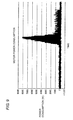
- FIG. 9 is a view illustrating an example of a supply electric power waveform in the case that the system power supply is supplied to a motor.
- the supply electric power waveform in which a peak is formed during the acceleration is obtained in the sampling in Step S12 in FIG. 8 .
- an outline of the supply electric power waveform in which the peak waveform is formed can be approximated to a right triangle.
- the supply electric power waveform is previously acquired before the threshold is calculated.
- the electric power is supplied from the system power supply 2 to the inverter 6, and the electric power is measured with the clamp type watt meter 13, which allows the supply electric power waveform to be sampled.
- the regenerative electric energy can be calculated by also acquiring the regenerative power waveform. Even if the measurement is not actually performed, data of the supply electric power waveform that is of the model is previously stored in the memory 32, and the data may be used.
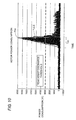
- FIG. 10 is a view illustrating an example of modeling of the supply electric power waveform in the case that the system power supply is supplied to the motor.
- Step S14 in FIG. 8 the modeling is performed in Step S14 in FIG. 8 .
- the supply electric power waveform is extracted while approximated to the right triangle in which the peak waveform is formed.
- the threshold of the electric energy, at which the peak assist discharge is started, is calculated such that the electric energy of the peak assist portion Ep[J] is supplied to a region where the peak of the right triangle is formed.
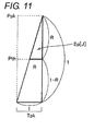
- FIG. 11 is a view illustrating the calculation of the threshold of the electric energy at which the peak assist discharge is started.
- the value (threshold) of the electric energy (motor power consumption) supplied from the system power supply is calculated in the case that the electric energy of the peak assist portion Ep[J] is supplied to the peak portion of the modeled right triangle. The value becomes start timing of the supply of the electric power.
- a threshold (peak assist discharge start threshold) Pth of the electric energy, at which the peak assist discharge is started is calculated based on the following equation.
- Ppk is the peak portion of the modeled right triangle, namely, the maximum electric energy value.
- Tpk is the acceleration period of the motor.
- the peak assist discharge is started when the value of the electric power supplied from the system power supply 2 reaches the calculated peak assist discharge start threshold Pth.
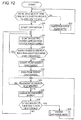
- FIG. 12 is a flowchart illustrating an operation of an electric storage device control system according to the embodiment.
- Step S20 it is determined whether the electric energy stored in the electric storage device is greater than or equal to the peak assist energy threshold. Specifically, the voltage level at the electric storage device 10 is measured to determine whether the voltage level is greater than or equal to the set peak assist energy threshold Thp.
- Step S20 When the electric energy stored in the electric storage device is less than the peak assist energy threshold (NO in Step S20), the system power supply charges the electric energy in the electric storage device (Step S22). The flow returns to Step S20.
- the processing is repeated until the electric energy stored in the electric storage device 10 is greater than or equal to the peak assist energy threshold Thp.
- Step S24 When the electric energy stored in the electric storage device is greater than or equal to the peak assist energy threshold (YES in Step S20), the operation is started (Step S24). Specifically, a motor control device (not illustrated) is driven to supply the electric power to the inverter 6 from the system power supply 2, thereby driving the motor 4.
- the supply electric power supplied from the system power supply is monitored (Step S26). Specifically, the value of the supply electric power supplied from the system power supply 2 is measured with the clamp type watt meter 13.
- Step S28 it is determined whether the supply electric power supplied from the system power supply 2 is greater than the peak assist discharge start threshold. Specifically, it is determined whether the measured electric power value is greater than the calculated peak assist discharge start threshold Pth.
- Step S26 The flow returns to Step S26 to repeat the processing until the supply electric power is greater than the peak assist discharge start threshold.
- the peak assist discharge is started (Step S30). Specifically, the electric storage device 10 supplies the electric energy of the peak assist portion to the inverter 6. Specifically, the electric energy of the peak assist portion can be discharged based on whether the voltage level at the electric storage device 10 decreases by a difference between the peak assist energy threshold Thp and the backup energy threshold Thb.
- the peak assist discharge is ended (Step S32).
- Step S34 it is determined whether the regenerative energy is generated. Specifically, the voltage level at the internal node of the inverter 6 is monitored, and whether the regenerative energy is generated is determined based on whether the voltage level is inverted.
- Step S34 When the regenerative energy is generated (YES in Step S34), the generated regenerative energy is charged in the electric storage device 10 (Step S36).
- Step S38 it is determined whether the electric energy stored in the electric storage device 10 is greater than or equal to the excess energy threshold. Specifically, it is determined whether the voltage level at the electric storage device 10 is greater than or equal to the excess energy threshold Tha.
- Step S38 When the electric energy stored in the electric storage device 10 is greater than or equal to the excess energy threshold (YES in Step S38), the flow goes to Step S40.
- Step S40 the flow goes to an excess discharge mode.
- the electric energy stored in the electric storage device 10 is less than the excess energy threshold (NO in Step S38)
- the flow returns to Step S26.
- the subsequent pieces of processing are identical to the above pieces of processing. Specifically, when the voltage level at the electric storage device 10 is less than the excess energy threshold Tha, the electric storage device 10 is charged until the voltage level at the electric storage device 10 is greater than or equal to the excess energy threshold Tha.
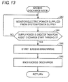
- FIG. 13 is a flowchart illustrating the excess discharge mode according to the embodiment.
- Step S42 the supply electric power supplied from the system power supply is monitored. Specifically, the value of the supply electric power supplied from the system power supply 2 is measured with the clamp type watt meter 13.
- Step S44 it is determined whether the supply electric power is greater than the peak assist discharge start threshold.
- Step S42 The flow returns to Step S42 to repeat the processing until the supply electric power is greater than the peak assist discharge start threshold.
- the excess discharge is started (Step S46).
- the excess discharge includes the peak assist discharge, and the electric storage device 10 supplies the electric energy of the peak assist portion to the inverter 6.
- the general electric power supplied from the system power supply 2 is supplied from the excess energy of the electric storage device 10.
- the excess discharge can be performed until the voltage level at the electric storage device 10 reaches the backup energy threshold Thb.
- Step S48 After the electric energy of the excess discharge portion is discharged, the excess discharge is ended (Step S48). The excess discharge is ended even if the regenerative energy is generated in the middle of the excess discharge.
- FIGS. 14A, 14B, and 14C are views illustrating a relationship among the drive of the motor, the electric power waveform supplied from the system power supply, and the electric storage capacity of the electric storage device according to the embodiment.
- the motor repeats a cycle, in which the motor is accelerated to the target rotation speed, driven at a constant speed, and then decelerated.
- the description in FIG. 14A is the same as the description in FIG. 3A .
- the electric energy is compensated by the peak assist discharge from the electric storage device 10 in addition to the system power supply.
- the electric energy is previously stored to the peak assist energy threshold in the electric storage device 10.
- the electric energy of the electric storage device 10 decreases by the electric energy of the peak assist portion.
- the regenerative energy is stored in the electric storage device 10 to raise the voltage level of the electric storage capacity.
- the electric energy supplied from the system power supply 2 is greater than the peak assist discharge start threshold again, the electric energy is compensated by the peak assist discharge from the electric storage device 10.
- the electric energy of the electric storage device 10 decreases by the electric energy of the peak assist portion.
- the regenerative energy is stored in the electric storage device 10 to raise the voltage level of the electric storage capacity again.
- the voltage level at the electric storage capacity is greater than or equal to the excess energy threshold. That is, the flow goes to an excess discharge mode.
- the peak assist electric energy is supplied by the excess discharge from the electric storage device 10.
- the excess energy is supplied instead of the system power supply 2.
- the excess energy is supplied to decrease the voltage level at the electric storage device 10 to the backup energy threshold.
- the regenerative energy is stored in the electric storage device 10 to raise the voltage level of the electric storage capacity.
- the processing is repeated in the same manner.
- the supply electric power supplied from the system power supply 2 is monitored, and the peak assist discharge is started when the supply electric power is greater than the peak assist discharge start threshold. Therefore, unlike the related art, it is not necessary to detect the momentary voltage drop of the electric power system, but the peak assist discharge can easily be performed.
- the regenerative energy is surely stored and discharged in and from the electric storage device, so that the efficient system can be constructed without generating the wasteful storage electric energy.
- the peak assist discharge start threshold is used as a trigger to start the excess discharge.
- the excess discharge may be started before the peak assist discharge start threshold, or the excess discharge may be started after the peak assist discharge.
- FIG. 15 is a view illustrating factory power consumption in the case of using the electric storage device control system according to the embodiment and in the case of a comparative example.
- the peak of the factory power consumption is maximized in the case that the regenerative energy is not used.
- the peak value can be suppressed compared with the case that the regenerative energy is not used.
- the regenerative energy is used, and the peak assist discharge is performed, which allows the peak value to be further suppressed.
- the maximum value of the electric energy supplied from the system power supply can be decreased. That is, cost can be reduced by decreasing the maximum electric energy of the electric energy purchased from a power producer.
- the EDLC is used as the electric storage device.
- any device may be used as long as the device can store and manage the electric energy.
- a lithium-ion capacitor (LiC) or a lithium-ion battery may be used instead of the EDLC.
- LiC lithium-ion capacitor
- a lithium-ion battery may be used instead of the EDLC.
- a range of use of the capacity may be restricted according to characteristics of the electric storage device.
- a State of Charge (SOC) is estimated according to the characteristics of the electric storage device, and the electric storage amount may be managed based on the estimation result.
- the inverter 6 connected to the motor 4 is described.
- the embodiment can also be applied to mechanisms, such as a servo driver connected to a servo motor, in which the regenerative energy is generated according to a given rule.
- the embodiment can be applied to either the case that the motor 4 is used as horizontal axis drive or the case that the motor 4 is used as vertical axis drive.
- the supply electric power supplied from the system power supply 2 is measured with the clamp type watt meter 13.
- the watt meter is not limited to the clamp type watt meter, but any type watt meter may be used as long as the supply electric power supplied from the system power supply 2 is measured.
- the supply electric power supplied from the system power supply 2 may be measured based on the DC voltage at the inverter 6 and the current passing through the inverter 6.
- 2 ... system power supply, 4 ... motor, 6 ... inverter, 8 ... bidirectional DC/DC converter, 10 ... electric storage device, 12 ... controller, 13 ... clamp type watt meter, 30 ... CPU, 32 ... memory, 34, 38, 40 ... ADC, 36 ... PWM circuit.
Landscapes
- Engineering & Computer Science (AREA)
- Power Engineering (AREA)
- Charge And Discharge Circuits For Batteries Or The Like (AREA)
- Supply And Distribution Of Alternating Current (AREA)
- Secondary Cells (AREA)
Applications Claiming Priority (1)
| Application Number | Priority Date | Filing Date | Title |
|---|---|---|---|
| JP2012058270A JP2013192413A (ja) | 2012-03-15 | 2012-03-15 | 蓄電デバイス制御方法、蓄電デバイス制御装置、蓄電デバイス制御システム |
Publications (2)
| Publication Number | Publication Date |
|---|---|
| EP2639921A2 true EP2639921A2 (fr) | 2013-09-18 |
| EP2639921A3 EP2639921A3 (fr) | 2014-09-10 |
Family
ID=48366109
Family Applications (1)
| Application Number | Title | Priority Date | Filing Date |
|---|---|---|---|
| EP13158913.7A Withdrawn EP2639921A3 (fr) | 2012-03-15 | 2013-03-13 | Procédé de commande pour un dispositif de stockage électrique, un dispositif pour contrôler un dispositif de stockage électrique et un système de commande pour un dispositif de stockage électrique |
Country Status (3)
| Country | Link |
|---|---|
| EP (1) | EP2639921A3 (fr) |
| JP (1) | JP2013192413A (fr) |
| CN (1) | CN103311941A (fr) |
Cited By (2)
| Publication number | Priority date | Publication date | Assignee | Title |
|---|---|---|---|---|
| DE102015226092A1 (de) * | 2015-12-18 | 2017-06-22 | Intrasys Gmbh Innovative Transport-Systeme | Volksbelustigungsvorrichtung mit mehreren Antriebsenergiequellen |
| EP3300208A1 (fr) * | 2016-09-23 | 2018-03-28 | Goodrich Control Systems | Appareil d'alimentation électrique pour un actionneur d'un véhicule aérospatial |
Families Citing this family (5)
| Publication number | Priority date | Publication date | Assignee | Title |
|---|---|---|---|---|
| KR101706030B1 (ko) * | 2014-06-19 | 2017-02-10 | 미쓰비시덴키 가부시키가이샤 | 교류 모터 구동 시스템 |
| JP5882429B1 (ja) * | 2014-09-12 | 2016-03-09 | 東芝エレベータ株式会社 | 電源装置 |
| CN105743112B (zh) * | 2016-04-27 | 2018-04-03 | 湖北文理学院 | 一种基于电池蓄能的交流柔性电力系统的控制方法 |
| JP7111557B2 (ja) * | 2018-08-23 | 2022-08-02 | ファナック株式会社 | 蓄電装置を有するモータ駆動システム |
| DE102019119969A1 (de) * | 2019-07-24 | 2021-01-28 | Volkswagen Aktiengesellschaft | Verfahren zum Anzeigen einer Warnmeldung |
Citations (1)
| Publication number | Priority date | Publication date | Assignee | Title |
|---|---|---|---|---|
| JP2009232526A (ja) | 2008-03-21 | 2009-10-08 | Meidensha Corp | 電力変換装置 |
Family Cites Families (12)
| Publication number | Priority date | Publication date | Assignee | Title |
|---|---|---|---|---|
| US5500561A (en) * | 1991-01-08 | 1996-03-19 | Wilhelm; William G. | Customer side power management system and method |
| JPH1141831A (ja) * | 1997-07-11 | 1999-02-12 | N T T Facilities:Kk | 電力貯蔵装置、及び電力貯蔵装置の運転方法 |
| JP2000069673A (ja) * | 1998-08-25 | 2000-03-03 | Hitachi Ltd | 電力貯蔵装置の制御方法および制御装置 |
| JP4512283B2 (ja) * | 2001-03-12 | 2010-07-28 | 株式会社小松製作所 | ハイブリッド式建設機械 |
| JP2003125537A (ja) * | 2001-10-11 | 2003-04-25 | Hokuriku Electric Power Co Inc:The | 電力貯蔵用二次電池の放電方法 |
| AT502460B1 (de) * | 2004-02-19 | 2009-01-15 | Siemens Ag Oesterreich | Einrichtung zur spitzenlast-abdeckung |
| JP2007332921A (ja) * | 2006-06-16 | 2007-12-27 | Shin Caterpillar Mitsubishi Ltd | ハイブリッド制御システムおよびハイブリッド式作業機械 |
| US8244419B2 (en) * | 2006-10-24 | 2012-08-14 | Mi-Jack Canada, Inc. | Marine power train system and method of storing energy in a marine vehicle |
| JP2011131829A (ja) * | 2009-12-25 | 2011-07-07 | Mitsubishi Fuso Truck & Bus Corp | ハイブリッド電気自動車の制御装置 |
| JP5510019B2 (ja) * | 2010-04-16 | 2014-06-04 | 富士通株式会社 | 電力制御方法、プログラム及び装置 |
| JP5533343B2 (ja) * | 2010-06-28 | 2014-06-25 | 富士通株式会社 | 電力平準化システム |
| WO2012014731A1 (fr) * | 2010-07-30 | 2012-02-02 | 三洋電機株式会社 | Dispositif de commande de demande |
-
2012
- 2012-03-15 JP JP2012058270A patent/JP2013192413A/ja active Pending
-
2013
- 2013-03-13 EP EP13158913.7A patent/EP2639921A3/fr not_active Withdrawn
- 2013-03-15 CN CN2013100830351A patent/CN103311941A/zh active Pending
Patent Citations (1)
| Publication number | Priority date | Publication date | Assignee | Title |
|---|---|---|---|---|
| JP2009232526A (ja) | 2008-03-21 | 2009-10-08 | Meidensha Corp | 電力変換装置 |
Cited By (3)
| Publication number | Priority date | Publication date | Assignee | Title |
|---|---|---|---|---|
| DE102015226092A1 (de) * | 2015-12-18 | 2017-06-22 | Intrasys Gmbh Innovative Transport-Systeme | Volksbelustigungsvorrichtung mit mehreren Antriebsenergiequellen |
| DE102015226092B4 (de) | 2015-12-18 | 2024-05-23 | Intrasys Gmbh Innovative Transport-Systeme | Volksbelustigungsvorrichtung mit einer Energieversorgungsvorrichtung mitmehreren Antriebsenergiequellen und Verfahren zur Steuerung derEnergieversorgungsvorrichtung |
| EP3300208A1 (fr) * | 2016-09-23 | 2018-03-28 | Goodrich Control Systems | Appareil d'alimentation électrique pour un actionneur d'un véhicule aérospatial |
Also Published As
| Publication number | Publication date |
|---|---|
| CN103311941A (zh) | 2013-09-18 |
| JP2013192413A (ja) | 2013-09-26 |
| EP2639921A3 (fr) | 2014-09-10 |
Similar Documents
| Publication | Publication Date | Title |
|---|---|---|
| EP2639921A2 (fr) | Procédé de commande pour un dispositif de stockage électrique, un dispositif pour contrôler un dispositif de stockage électrique et un système de commande pour un dispositif de stockage électrique | |
| JP4347982B2 (ja) | エレベーターの制御装置 | |
| JP5826440B1 (ja) | 交流モータ駆動システム | |
| CN101677144B (zh) | 包括超电容器的自治系统中电池的脉冲充电的方法 | |
| US9744876B2 (en) | Electric vehicle | |
| CN205509921U (zh) | 电动机驱动装置 | |
| EP2481624A1 (fr) | Système de charge de véhicule et véhicule électrique équipé de ce dernier | |
| US10081260B2 (en) | Supplemental charging control device for electric vehicle | |
| US20140372050A1 (en) | Life diagnosis method for power storage device | |
| JP6462905B2 (ja) | 位相シフトフルブリッジ充電器の制御システムおよび制御方法 | |
| KR20160013651A (ko) | 친환경 차량용 충전기의 충전 제어 방법 | |
| Saichand et al. | PWM block method for control of an ultracapacitor-based bidirectional DC–DC backup system | |
| US10112493B2 (en) | Charge-discharge control device | |
| JP2016052869A (ja) | 充電制御装置 | |
| JP5196011B2 (ja) | 充電制御システム | |
| US9580067B2 (en) | Charging/discharging control system for electricity storage device | |
| GB2563548A (en) | Electric power control device and vehicle | |
| JP2010119180A (ja) | 車両の制御装置 | |
| JP2011049032A (ja) | 電池昇温制御システム | |
| JP6402038B2 (ja) | 電力制御装置 | |
| JP6357343B2 (ja) | 電力貯蔵装置 |
Legal Events
| Date | Code | Title | Description |
|---|---|---|---|
| PUAI | Public reference made under article 153(3) epc to a published international application that has entered the european phase |
Free format text: ORIGINAL CODE: 0009012 |
|
| AK | Designated contracting states |
Kind code of ref document: A2 Designated state(s): AL AT BE BG CH CY CZ DE DK EE ES FI FR GB GR HR HU IE IS IT LI LT LU LV MC MK MT NL NO PL PT RO RS SE SI SK SM TR |
|
| AX | Request for extension of the european patent |
Extension state: BA ME |
|
| PUAL | Search report despatched |
Free format text: ORIGINAL CODE: 0009013 |
|
| AK | Designated contracting states |
Kind code of ref document: A3 Designated state(s): AL AT BE BG CH CY CZ DE DK EE ES FI FR GB GR HR HU IE IS IT LI LT LU LV MC MK MT NL NO PL PT RO RS SE SI SK SM TR |
|
| AX | Request for extension of the european patent |
Extension state: BA ME |
|
| RIC1 | Information provided on ipc code assigned before grant |
Ipc: H02J 3/32 20060101AFI20140805BHEP Ipc: H02J 3/00 20060101ALN20140805BHEP Ipc: H02J 7/34 20060101ALN20140805BHEP |
|
| STAA | Information on the status of an ep patent application or granted ep patent |
Free format text: STATUS: THE APPLICATION IS DEEMED TO BE WITHDRAWN |
|
| 18D | Application deemed to be withdrawn |
Effective date: 20150311 |