EP2640178B1 - Vorrichtung zum streifenförmigen aufbringen von düngemittel - Google Patents
Vorrichtung zum streifenförmigen aufbringen von düngemittel Download PDFInfo
- Publication number
- EP2640178B1 EP2640178B1 EP11779184.8A EP11779184A EP2640178B1 EP 2640178 B1 EP2640178 B1 EP 2640178B1 EP 11779184 A EP11779184 A EP 11779184A EP 2640178 B1 EP2640178 B1 EP 2640178B1
- Authority
- EP
- European Patent Office
- Prior art keywords
- booms
- set forth
- support
- transport position
- vehicle
- Prior art date
- Legal status (The legal status is an assumption and is not a legal conclusion. Google has not performed a legal analysis and makes no representation as to the accuracy of the status listed.)
- Not-in-force
Links
Images


Classifications
-
- A—HUMAN NECESSITIES
- A01—AGRICULTURE; FORESTRY; ANIMAL HUSBANDRY; HUNTING; TRAPPING; FISHING
- A01B—SOIL WORKING IN AGRICULTURE OR FORESTRY; PARTS, DETAILS, OR ACCESSORIES OF AGRICULTURAL MACHINES OR IMPLEMENTS, IN GENERAL
- A01B73/00—Means or arrangements to facilitate transportation of agricultural machines or implements, e.g. folding frames to reduce overall width
- A01B73/02—Folding frames
- A01B73/06—Folding frames foldable about a vertical axis
- A01B73/067—Folding frames foldable about a vertical axis to a position essentially rearward of the axis, in relation to the direction of travel
-
- A—HUMAN NECESSITIES
- A01—AGRICULTURE; FORESTRY; ANIMAL HUSBANDRY; HUNTING; TRAPPING; FISHING
- A01B—SOIL WORKING IN AGRICULTURE OR FORESTRY; PARTS, DETAILS, OR ACCESSORIES OF AGRICULTURAL MACHINES OR IMPLEMENTS, IN GENERAL
- A01B73/00—Means or arrangements to facilitate transportation of agricultural machines or implements, e.g. folding frames to reduce overall width
- A01B73/02—Folding frames
- A01B73/06—Folding frames foldable about a vertical axis
-
- A—HUMAN NECESSITIES
- A01—AGRICULTURE; FORESTRY; ANIMAL HUSBANDRY; HUNTING; TRAPPING; FISHING
- A01C—PLANTING; SOWING; FERTILISING
- A01C23/00—Distributing devices specially adapted for liquid manure or other fertilising liquid, including ammonia, e.g. transport tanks or sprinkling wagons
-
- A—HUMAN NECESSITIES
- A01—AGRICULTURE; FORESTRY; ANIMAL HUSBANDRY; HUNTING; TRAPPING; FISHING
- A01C—PLANTING; SOWING; FERTILISING
- A01C23/00—Distributing devices specially adapted for liquid manure or other fertilising liquid, including ammonia, e.g. transport tanks or sprinkling wagons
- A01C23/008—Tanks, chassis or related parts
-
- A—HUMAN NECESSITIES
- A01—AGRICULTURE; FORESTRY; ANIMAL HUSBANDRY; HUNTING; TRAPPING; FISHING
- A01C—PLANTING; SOWING; FERTILISING
- A01C23/00—Distributing devices specially adapted for liquid manure or other fertilising liquid, including ammonia, e.g. transport tanks or sprinkling wagons
- A01C23/02—Special arrangements for delivering the liquid directly into the soil
- A01C23/021—Sludge injectors, i.e. liquid manure injectors
- A01C23/022—Continuous injection tools
-
- A—HUMAN NECESSITIES
- A01—AGRICULTURE; FORESTRY; ANIMAL HUSBANDRY; HUNTING; TRAPPING; FISHING
- A01C—PLANTING; SOWING; FERTILISING
- A01C23/00—Distributing devices specially adapted for liquid manure or other fertilising liquid, including ammonia, e.g. transport tanks or sprinkling wagons
- A01C23/04—Distributing under pressure; Distributing mud; Adaptation of watering systems for fertilising-liquids
- A01C23/047—Spraying of liquid fertilisers
-
- B—PERFORMING OPERATIONS; TRANSPORTING
- B05—SPRAYING OR ATOMISING IN GENERAL; APPLYING FLUENT MATERIALS TO SURFACES, IN GENERAL
- B05B—SPRAYING APPARATUS; ATOMISING APPARATUS; NOZZLES
- B05B13/00—Machines or plants for applying liquids or other fluent materials to surfaces of objects or other work by spraying, not covered by groups B05B1/00 - B05B11/00
- B05B13/005—Machines or plants for applying liquids or other fluent materials to surfaces of objects or other work by spraying, not covered by groups B05B1/00 - B05B11/00 mounted on vehicles or designed to apply a liquid on a very large surface, e.g. on the road, on the surface of large containers
-
- B—PERFORMING OPERATIONS; TRANSPORTING
- B05—SPRAYING OR ATOMISING IN GENERAL; APPLYING FLUENT MATERIALS TO SURFACES, IN GENERAL
- B05B—SPRAYING APPARATUS; ATOMISING APPARATUS; NOZZLES
- B05B13/00—Machines or plants for applying liquids or other fluent materials to surfaces of objects or other work by spraying, not covered by groups B05B1/00 - B05B11/00
- B05B13/02—Means for supporting work; Arrangement or mounting of spray heads; Adaptation or arrangement of means for feeding work
- B05B13/04—Means for supporting work; Arrangement or mounting of spray heads; Adaptation or arrangement of means for feeding work the spray heads being moved during spraying operation
-
- B—PERFORMING OPERATIONS; TRANSPORTING
- B05—SPRAYING OR ATOMISING IN GENERAL; APPLYING FLUENT MATERIALS TO SURFACES, IN GENERAL
- B05B—SPRAYING APPARATUS; ATOMISING APPARATUS; NOZZLES
- B05B3/00—Spraying or sprinkling apparatus with moving outlet elements or moving deflecting elements
- B05B3/18—Spraying or sprinkling apparatus with moving outlet elements or moving deflecting elements with elements moving in a straight line, e.g. along a track; Mobile sprinklers
Definitions
- the present invention relates to an apparatus for strip-applying a fertilizer on agricultural land by means of drag hoses, which is adapted for mounting at the rear of a tanker vehicle, with two arms, each of which can be pivoted about a vertical axis between an application position and a transport position, with a Stützelnraum which is arranged pivotably about a vertical axis on the device and is adapted to support the boom in the transport position relative to the roadway in a spaced-apart from the axis support portion.
- Devices of the type mentioned above are usually used for environmentally friendly distribution of organic suspensions such as liquid manure on agricultural land. With the above-mentioned devices, a ground-level application is achieved, so that the distribution of ammonia is reduced in the ambient air.
- the application of fertilizer by means of tow hoses has proven itself, even on overgrown soil.
- the tow hoses are to be attached in a known manner to the devices for spreading the fertilizer.
- the attached to the device boom between a transport position and a dispensing position are back and forth.
- the arms are spread laterally relative to the direction of travel of the tanker holding the device.
- a maximum application width is achieved at a spread at right angles to the direction of travel or to the longitudinal direction of the vehicle.
- the pivoting movement preferably takes place about a vertical axis. Under vertical orientation is in this case a substantially vertical orientation of the Pivot axis understood relative to the vehicle ground, or a vertical orientation relative to a horizontal as assumed vehicle body.
- Pulled by tractors tanker provide in a known manner before pivoting boom, which are folded for transport from the laterally spread application position forward to the sides of the tanker.
- self-drivers - vehicles with their own drive and a short tank on a uniform vehicle body - is such a folding arrangement due to the high vehicle width, however, not feasible.
- a linkage device for a distribution vehicle which is adapted for strip-spreading fertilizers on agricultural land by means of drag hoses and having two arms, each of which proposes about a vertical axis between an application position and a transport position behind the tanker such that a maximum width of 3 m is maintained behind the tanker.
- the document proposes to arrange a left arm and a right arm on two different length pivot arms behind the tank and to pivot by 180 ° from a transport position to the discharge position and back.
- the invention was therefore based on the object to provide a device of the type mentioned, which allows a larger application width and at the same time ensures good handling of the device during transport.
- the invention solves the underlying task by a device according to claim 1.
- the invention takes advantage of the finding that the provision of a support device on the device provides the opportunity to spend the boom in a transport position in which the boom are pivoted straight back behind the tanker, without having to be nested.
- the known self-propelled vehicles which have only a short vehicle length
- either the folding down of the boom was not possible due to the change in the center of gravity, or the order width which was still achievable under an acceptable change of center of gravity was too low.
- the support device allows folding down basically arbitrarily long boom to the rear. As long as the distance between the support section and the rear of the vehicle is large enough, can thus be achieved in much larger order widths, which is limited only by the maximum permissible for road use team length.
- the support means comprises a drawbar, which is pivotable about the vertical axis and in the support section has one or more support wheels whose running direction is substantially parallel to a pulling direction of the drawbar.
- the drawbar is connected at a first end portion to a support frame of the device.
- the support portion is located at a second end portion of the support means opposite this end portion, so that beyond the support portion or the support wheels or unnecessary support of the device remains and the swinging is minimized when cornering. As a result, the handling in transport operation is improved.
- the or the support wheels are not driven.
- the support means for each of the two arms each have a support for transmitting the weight of the boom to the one or more support wheels.
- the supports of the two arms are preferably mounted on a cross member which is oriented substantially parallel to a plane in which the axes of the arms lie. Characterized in that the cross member is aligned substantially parallel to the plane of the axes of the boom, the boom are trapezoidally moved when the vehicle is cornering.
- the two arms are arranged in the transport position substantially parallel to each other. In this case, during cornering of the vehicle when the device is mounted in the transport position, a parallelogram-like movement of the arms relative to each other occurs.
- the device according to the invention is advantageously further developed in that the arms are height-adjustable by means of a lifting device, and in the transport position by means of lowering in contact with the respective support can be brought.
- the booms are brought by lifting out of contact with the respective support, and then can be pivoted from the transport position to the discharge position.
- the supports each have locking elements, with which the boom in the transport position by means of lowering can be brought into engagement.
- the locking elements prevent lateral, unintentional disengagement of the arms from the support of the device.
- the locking elements preferably have U-shaped holding sections and / or optionally further latching elements, such as hooks or clamping elements.
- the locking elements are preferably designed to prevent by means of substantially vertically formed guide elements inadvertent lateral pivoting of the boom. The danger for this is especially given when changes in height of the boom relative to the support means and in particular the respective support due to unevenness of the ground.
- the guiding elements are set up to feed the arms back to the support.
- a U-shaped holding portion preferably serve the two legs of the U-profile as guiding elements.
- the support means due to the pivoting about the horizontal axis permits a change in angle of the drawbar, unevenness on the road such as compressions or terrain hills are compensated during driving.
- the support means is pivotable about the horizontal axis such that the support means gets out of contact with the ground.
- the support means is pivoted to a substantially vertical position when the outriggers are out of the transport position. In particular, this is advantageous when the arms are in the dispensing position or on the way to the dispensing position.
- the support means is not needed in these cases, since due to the pivoting movement of the center of gravity of the support device is moved in the direction of the vehicle.
- the arms are pivotable in the dispensing position according to a further advantageous embodiment of the invention about a horizontal axis.
- the horizontal axis is preferably aligned in the longitudinal direction of the vehicle, so that pivoting this axis reduces the height of the right arm relative to the ground, at the same time the height of the opposite arm is increased to the local ground.
- the pivotability of the axis should preferably be +/- 10 ° relative to the horizontal and be infinitely adjustable.
- the cantilevers are preferably each pivotally mounted about the respective vertical axis on a pivot frame.
- the swing frame is preferably pivotally mounted about a horizontal axis on the support frame.
- the horizontal axis about which the pivot frame is pivotally mounted on the support frame is preferably the same axis about which the arms are horizontally pivotable in the deployment position.
- the cantilevers are mounted separately pivotable about a respective horizontal axis or about the same horizontal axis in deployment position.
- the provision of the swing frame is considered advantageous because it provides a mechanical joint connection with the rest of the device.
- the lifting device is formed on the tanker vehicle, and the support frame is adapted for mounting on the lifting device of the tanker vehicle.
- the lifting device is already formed on the tanker, the structure of the device according to the invention is simplified as a whole and the relevant own weight is reduced.
- the entire support frame is moved by the provided on the tanker lifting device in height.
- the supporting part of the support means for example the support wheel, remains on the ground due to the pivotability of the support means about the horizontal axis. It is only the support frame, and other related parts raised. This may be according to preferred embodiments of the swing frame and / or the pivotally mounted boom.
- the lifting device is formed on the support frame, and the swing frame is vertically movable by means of the lifting device relative to the support frame. This is particularly advantageous for vehicles without their own lifting device. In vehicles that are themselves already provided with a lifting device, however, the range of motion in the height adjustment is increased again by an additional lifting device, although a higher weight and higher complexity of the control must be taken into account.
- the outriggers each have an extension segment, which is arranged between a transport position and an application position and is pivotable back and forth on an end section of the respective jib.
- the extension segment is preferably pivotally mounted about a horizontal axis at the end portion of the respective boom and pivoted in the transport position by 180 ° in the direction of travel forward.
- the respective extension segment is removed from the transport position in pivots the application position, whereby a further increase in the application width is achieved.
- the cross member is designed to be height adjustable.
- the height support is adapted to compensate for a height change of the boom occurring, for example due to road bumps relative to the respective support by the cross member tracked by a height adjustment of the supports.
- the height adjustment is preferably spring assisted or motorized.
- the invention solves the underlying task further in a tank vehicle of the type mentioned in that the tanker vehicle has a dispensing device, which is formed according to an advantageous embodiment of the present invention.
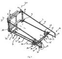
- FIG. 1 the device according to the invention for the application of fertilizers is shown schematically spatially.
- the device 1 has two arms 3, of which a boom 3 is mounted pivotably on a pivot frame 5 about a vertical axis A1.
- the second boom 3 is pivotally mounted on the pivot frame 5 about a vertical axis A2.
- Both arms 3 are identical, so that only one of the arms is provided with reference numerals.
- the booms 3 each have an upper and lower bearing section 9. Between the respective bearing sections 9 extends a vertical strut 17 forms a vehicle-proximal end of the boom 3.
- At the opposite end of the respective strut 17 of the respective arm 3 each have a second vertical strut 15 is arranged.
- the second vertical strut 15 and the first vertical strut 17 are formed substantially parallel to each other.
- the second vertical strut 15 is shorter than the first vertical strut 17, so that the boom 3 is formed overall trapezoidal.
- a lower horizontal strut 13 is oriented substantially horizontally, while an upper horizontal strut 11 is aligned sloping in the direction of the second vertical strut 15.
- the pivoting frame 5 is pivotally mounted on a support frame 7 about a horizontal axis, indicated by reference numeral D.
- the support frame 7 is on a (in FIG. 1 not shown) tanker attachable.
- the axis D extends substantially in the longitudinal direction of the tanker vehicle and substantially perpendicular to the axes A1 and A2.
- a receptacle 18, which can be coupled to a drawbar 27, is arranged on a region near the ground in the mounted state of the device. In FIG. 1 a drawbar 27 coupled thereto is shown.
- the drawbar 27 is pivotable about the vertical axis B relative to the support frame 7 of the device 1.
- the connection between receptacle 18 and drawbar 27 is arranged in an end portion 19 of the drawbar 27.
- a support section 21 is located at a distance from the end section of the drawbar.
- the support section 21 and the drawbar 27 are part of a support device 10.
- the support device 10 has a support wheel 29 in the support section 21.
- the support wheel 29 is mounted by means of an axis 31 in a wheel arch 33.
- the wheel arch 33 is arranged at an end of the drawbar 27 opposite the end section 19.
- On the wheel arch 33 a cross member 35 is arranged.
- two supports 23 are arranged on the cross member 35.
- the supports 23 are designed to receive a respective arm 3.
- FIG. 1 are the boom 3 in each case in the transport position and in engagement with the supports 23 and are supported by this.
- each case one or more locking elements 25 are arranged on the supports 23, which keep the horizontal strut 13 of the respective arm 3 locked in the transport position. Furthermore, at least one vertically aligned guide element 37 is formed on the supports in each case. The at least one guiding element 37 is designed for guiding in each case a height-adjusted arm 3 against unintentional lateral pivoting.
- the support device 10 is formed pivotable relative to the support frame 7 of the device about the horizontal axis C.
- Each of the two cantilevers 3 has an end portion 16 which is arranged opposite to the bearing of the respective cantilever.
- the boom 3 is arranged in each case in this end portion (not shown) for receiving an extension segment which can be pivoted back and forth between a transport position and an application position.
- FIG. 2 shows a top view of a device according to a preferred embodiment of the present invention, which is mounted on a tanker vehicle 100.
- the tanker 100 is located in FIG. 2 shown state in a cornering.
- the device 1 runs after the tanker 100 by the boom 3 are each supported by the support means 10 and held in the respective support 23.
- the cross member 35 is about an axis E (see FIG. 1 ) pivotally mounted on the wheel arch 33 and arranged parallel to a plane in which the axes are A1 and A2 of the boom 3. This plane is further formed parallel to the swing frame 5 and the support frame 7.
- the booms 3 are aligned parallel to one another, so that the support device 10 tracks the boom 3 parallelogram-like behind the vehicle 100.
- the pivotal movement of the device 1 in accordance with the support means 10 is also indicated by arrow 20.
- the drawbar 27 of the support device 10 is pivoted about the vertical axis B.
- the axis B, as in FIG. 2 shown in the same plane as the pivot axes A1 and A2.
- the vehicle 100 has a longitudinal axis which is substantially parallel to the axis D, about which the pivot arm 5 is pivotable relative to the support arm.
- FIGS. 3 and 4 the device 1 according to the invention is shown in side view.
- FIG. 3 shows the device 1 in a rear view (in the forward direction of travel of the vehicle) without vehicle 100.
- FIG. 4 shows a side projection of the Device off FIG. 3 with two indicated operating states. With regard to the extent identical reference numerals to the previous FIGS. 1 and 2 directed.
- FIGS. 3 and 4 is also the adjustability of the device 1 illustrated.
- the arms 3 of the device 1 are height-adjustable in the direction of the arrows 30 relative to the vehicle 100.
- the support wheel 29 stops on the ground, whereby the angle of the drawbar 27 relative to the axis C and the rest of the device 1 changed.
- the boom 3 are released from the position in their respective support 23 and moved along the guide 37 in height. After completed height adjustment, the boom 3 are pivoted from the transport position to the discharge position. Following or during this, the support means 10 is pivoted about the axis C in a substantially vertical position upwards.
- the support device 10 is thus approximated to the support frame 7 and the swing frame 5, so that the length of the composite vehicle 100 and device 1 (see FIG. 2 ) is minimized.
Landscapes
- Life Sciences & Earth Sciences (AREA)
- Soil Sciences (AREA)
- Engineering & Computer Science (AREA)
- Environmental Sciences (AREA)
- Water Supply & Treatment (AREA)
- Mechanical Engineering (AREA)
- Catching Or Destruction (AREA)
- Fertilizing (AREA)
Description
- Die vorliegende Erfindung betrifft eine Vorrichtung zum streifenförmigen Aufbringen eines Düngemittels auf landwirtschaftliche Nutzflächen mittels Schleppschläuchen, die zur Montage an dem Heck eines Tankfahrzeugs eingerichtet ist, mit zwei Auslegern, die jeweils um eine vertikale Achse zwischen einer Ausbringposition und einer Transportposition hin- und herschwenkbar sind, mit einer Stützelnrichtung, welche um eine vertikale Achse schwenkbar an der Vorrichtung angeordnet ist und dazu ausgebildet ist, die Ausleger in der Transportposition gegenüber der Fahrbahn in einem von der Achse beabstandeten Stützabschnitt zu stützen.
- Vorrichtungen der vorstehend genannten Art werden gewöhnlicherweise zur umweltschonenden Verteilung organischer Suspensionen wie beispielsweise Gülle auf landwirtschaftlichen Nutzflächen eingesetzt. Mit den vorstehend genannten Vorrichtungen wird eine bodennahe Applikation erzielt, so dass die Verteilung von Ammoniak in der Umgebungsluft gemindert wird. Die Ausbringung von Düngemittel mittels Schleppschläuchen hat sich bewährt, auch auf bewachsenem Boden. Die Schleppschläuche sind in bekannter Weise an den Vorrichtungen zum Ausbringen des Düngemittels anzubringen.
- Um eine möglichst große Auftragsbreite im Ausbring-Betrieb zu erreichen, sind die an der Vorrichtung angebrachten Ausleger zwischen einer Transportposition und einer Ausbringposition hin- und herschwenkbar. In der Ausbringposition sind die Ausleger relativ zu der Fahrtrichtung des die Vorrichtung haltenden Tankfahrzeugs seitlich abgespreizt. Eine maximale Auftragsbreite wird bei einer Abspreizung im rechten Winkel zur Fahrtrichtung beziehungsweise zur Längsrichtung des Fahrzeugs erreicht. Die Schwenkbewegung erfolgt vorzugsweise um eine vertikale Achse. Unter vertikaler Ausrichtung wird hierbei eine im Wesentlichen senkrechte Ausrichtung der Schwenkachse relativ zum Fahrzeug-Untergrund verstanden, bzw. eine senkrechte Ausrichtung relativ zu einem als horizontal angenommenen Fahrzeugaufbau.
- Um das Tankfahrzeug an seinen Bestimmungsort zum Ausbringen des Düngemittels zu verbringen, ist es oftmals notwendig, das Fahrzeug über öffentliche Straßen oder Wirtschaftswege zu bewegen. Die Vorrichtung zum Ausbringen von Düngemittel kann folglich während des Transports nicht in ihrer Ausbringposition verbleiben.
- Von Zugmaschinen gezogene Tankwagen sehen in bekannter Weise schwenkbare Ausleger vor, welche zum Transport von der seitlich abgespreizten Ausbringposition nach vorne an die Seiten des Tankwagens herangeklappt werden. Bei sogenannten Selbstfahrern - Fahrzeuge mit eigenen Antrieb und einem kurzen Tank auf einem einheitlichen Fahrzeugaufbau - ist eine solche Klappanordnung auf Grund der hohen Fahrzeugbreite allerdings nicht umsetzbar.
- Aus der
DE 200 17 937 U1 ist eine Gestängevorrichtung für ein Verteilerfahrzeug bekannt, welche zum streifenförmigen Ausbringen von Düngemittel auf landwirtschaftlichen Nutzflächen mittels Schleppschläuchen eingerichtet ist und zwei Ausleger aufweist, die jeweils um eine vertikale Achse zwischen einer Ausbringposition und einer Transportposition hinter dem Tankwagen derart vorschlägt, dass eine maximale Breite von 3 m hinter dem Tankwagen eingehalten wird. Die Druckschrift schlägt vor, einen linken Ausleger und einen rechten Ausleger an zwei unterschiedlich langen Schwenkarmen hinter dem Tank anzuordnen und um jeweils 180° von einer Transportposition in die Ausbringposition und zurück zu verschwenken. - Mit der dort vorgeschlagenen Lösung sind allerdings lediglich Auftragsbreiten von bis zu 9 m erreichbar. Zudem erfordert die dort vorgeschlagene Lösung einen erhöhten Teileaufwand. Weiterhin können der linke und rechte Ausleger nicht zeitgleich verschwenkt werden, da ein Ausleger den anderen in der Transportposition verdeckt.
- Aus der
DE 202008 015 564 A1 ist eine Vorrichtung nach dem Obergegriff des Anspruchs 1 bekannt. - Der Erfindung lag folglich die Aufgabe zu Grunde, eine Vorrichtung der eingangs genannten Art anzugeben, welche eine größere Auftragsbreite ermöglicht und gleichzeitig eine gute Handhabbarkeit der Vorrichtung beim Transport gewährleistet.
- Die Erfindung löst die ihr zu Grunde liegende Aufgabe durch einer Vorrichtung nach dem Anspruch 1. Die Erfindung macht sich die Erkenntnis zu Nutze, dass das Vorsehen einer Stützeinrichtung an der Vorrichtung die Möglichkeit schafft, die Ausleger in eine Transportposition zu verbringen, in welcher die Ausleger gerade nach hinten hinter das Tankfahrzeug geschwenkt sind, ohne ineinander verschachtelt werden zu müssen. Bei den bekannten Selbstfahrern, die nur eine kurze Fahrzeuglänge aufweisen, war entweder das Abklappen der Ausleger nach hinten auf Grund der Schwerpunktveränderung nicht möglich, oder die unter akzeptabler Schwerpunktsveränderung noch erreichbare Auftragsbreite war zu gering. Die Stützeinrichtung erlaubt ein Abklappen prinzipiell beliebig langer Ausleger nach hinten. Solange der Abstand zwischen dem Stütz-Abschnitt und dem Heck des Fahrzeugs groß genug ist, lassen sich somit im deutlich größere Auftragsbreiten erreichen, die nur durch die maximal für den Straßenbetrieb zulässige Gespann-Länge begrenzt wird.
- Die Erfindung wird vorteilhaft dadurch weitergebildet, dass die Stützeinrichtung eine Zugdeichsel aufweist, welche um die vertikale Achse schwenkbar ist und in dem Stütz-Abschnitt ein oder mehrere Stützräder aufweist, deren Laufrichtung im Wesentlichen parallel zu einer Zugrichtung der Zugdeichsel ist. Durch eine derartige Ausrichtung der Stützräder ist gewährleistet, dass die Stützeinrichtung im Betrieb des Fahrzeugs jedenfalls bei Vorwärtsfahrt des Fahrzeugs Im Wesentlichen spurtreu dem Fahrzeug nachläuft. Das eine beziehungsweise die mehreren Stützräder folgen der durch die Zugdeichsel vorgegebenen Bewegung. Nachdem die Stützeinrichtung auch die Ausleger stützt, laufen die nach hinten zur Stützeinrichtung verschwenkten Ausleger in Transportposition ebenfalls der von dem Fahrzeug vorgegebenen Bewegungsrichtung bei Kurvenfahrten. Die mittels der Stützeinrichtung abgestützte Vorrichtung in Transportposition weist ein Fahrverhalten auf, welches mit einem einachsigen Anhänger vergleichbar ist. Vorzugsweise ist die Zugdeichsel an einem ersten Endabschnitt mit einem Tragrahmen der Vorrichtung verbunden. Weiter vorzugsweise befindet sich der Stützabschnitt an einem diesem Endabschnitt gegenüberliegenden zweiten Endabschnitt der Stützeinrichtung, so dass jenseits des Stützabschnitts bzw. des oder der Stützräder kein unnötiger Überstand der Vorrichtung verbleibt und das Ausschwenken bei Kurvenfahrt minimiert wird. Hierdurch wird die Handhabbarkeit im Transport-Betrieb verbessert. In einer besonders bevorzugten Ausführungsform sind das bzw. die Stützräder nicht angetrieben.
- In einer bevorzugten Ausführungsform der Erfindung weist die Stützeinrichtung für jeden der beiden Ausleger jeweils ein Auflager zum Übertragen der Gewichtskraft der Ausleger auf das eine oder die mehreren Stützräder auf.
- Die Auflager der beiden Ausleger sind vorzugsweise an einem Querträger montiert, welcher im Wesentlichen parallel zu einer Ebene ausgerichtet ist, in welcher die Achsen der Ausleger liegen. Dadurch, dass der Querträger im Wesentlichen parallel zu der Ebene der Achsen der Ausleger ausgerichtet ist, werden die Ausleger trapezförmig bewegt, wenn das Fahrzeug sich In der Kurvenfahrt befindet.
- Besonders bevorzugt ist es, wenn die beiden Ausleger in der Transportposition im Wesentlichen parallel zueinander angeordnet sind. In diesem Fall tritt während der Kurvenfahrt des Fahrzeugs bei montierter Vorrichtung in Transportposition eine parallelogrammartige Bewegung der Ausleger relativ zueinander auf.
- Die erfindungsgemäße Vorrichtung wird dadurch vorteilhaft weitergebildet, dass die Ausleger mittels einer Hubeinrichtung höhenbeweglich sind, und in der Transportposition mittels Absenken in Kontakt mit dem jeweiligen Auflager bringbar sind. Im Gegenzug werden die Ausleger mittels Anheben außer Kontakt mit dem jeweiligen Auflager gebracht, und lassen sich sodann von der Transportposition in die Ausbringposition schwenken. Vorzugsweise weisen die Auflager jeweils Arretierelemente auf, mit denen die Ausleger in der Transportposition mittels Absenken in Eingriff bringbar sind. Die Arretierelemente verhindern ein seitliches, unbeabsichtigtes Außereingriffgeraten der Ausleger von der Stützeinrichtung der Vorrichtung. Die Arretierelemente weisen vorzugsweise U-förmige Halteabschnitte auf und/oder optional weitere Rastelemente, wie beispielsweise Haken oder Klemmelemente. Die Arretierelemente sind vorzugsweise dazu ausgebildet, mittels im Wesentlichen vertikal ausgebildeten Führ-Elementen ein unbeabsichtigtes seitliches Schwenken der Ausleger zu unterbinden. Die Gefahr hierfür ist insbesondere dann gegeben, wenn sich aufgrund von Unebenheiten des Untergrunds die Höhe der Ausleger relativ zu der Stützeinrichtung und insbesondere dem jeweiligen Auflager ändert. Die Führ-Elemente sind dazu eingerichtet, die Ausleger wieder dem Auflager zuzuführen. Bei einem U-förmigen Halteabschnitt dienen vorzugsweise die beiden Schenkel des U-Profils als Führ-Elemente.
- Gemäß der erfindungsgemäßen Vorrichtung ist die Stützeinrichtung in dem Endabschnitt um eine horizontale Achse schwenkbar gelagert. Dadurch, dass die Stützeinrichtung infolge der Schwenkbarkeit um die horizontale Achse eine Winkeländerung der Zugdeichsel zulässt, werden Unebenheiten auf der Fahrbahn wie beispielsweise Kompressionen oder Geländekuppen im Fahrbetrieb ausgeglichen. Die Stützeinrichtung ist derart um die horizontale Achse schwenkbar, dass die Stützeinrichtung außer Kontakt mit dem Boden gerät. Erfindungsgemäß wird die Stützeinrichtung in eine im Wesentlichen vertikale Position geschwenkt, wenn die Ausleger sich außerhalb der Transportposition befinden. Insbesondere ist dies vorteilhaft, wenn die Ausleger sich in der Ausgabeposition oder auf dem Weg in die Ausgabeposition befinden. Die Stützeinrichtung wird in diesen Fällen nicht benötigt, da auf Grund der Schwenkbewegung der Schwerpunkt der Stützeinrichtung in Richtung Fahrzeug bewegt wird. Zum Einhalten einer Kippstabilität ist es folglich nicht mehr notwendig, die Stützeinrichtung auf dem Boden weiter hinter dem Fahrzeug herzuziehen. Darüberhinaus wird durch das Verschwenken der Stützeinrichtung derart, dass sie außer Kontakt mit dem Boden gerät oder in eine im Wesentlichen vertikale Position, die Manövrierfähigkeit und Beweglichkeit des mit der erfindungsgemäßen Vorrichtung versehen Fahrzeugs weiter erhöht.
- Die Ausleger sind in der Ausbringposition gemäß einer weiteren vorteilhaften Ausführungsform der Erfindung um eine horizontale Achse schwenkbar. Die horizontale Achse ist vorzugsweise in Längsrichtung des Fahrzeugs ausgerichtet, so dass ein Verschwenken dieser Achse die Höhe des rechten Auslegers gegenüber dem Untergrund verringert, wobei gleichzeitig die Höhe des gegenüberliegenden Auslegers zum dortigen Untergrund erhöht wird. Eine Schräglage des Fahrzeugs, beispielsweise aufgrund ungleich tief eingesunkener Räder, wird ausgeglichen. Dabei sollte die Verschwenkbarkeit der Achse vorzugsweise +/-10° gegenüber der Horizontalen betragen und stufenlos einstellbar sein.
- Die Ausleger sind vorzugsweise jeweils um die jeweilige vertikale Achse schwenkbar an einem Schwenkrahmen gelagert. Der Schwenkrahmen ist vorzugsweise um eine horizontale Achse schwenkbar an dem Tragrahmen gelagert. Die horizontale Achse, um welche der Schwenkrahmen schwenkbar an dem Tragrahmen gelagert ist, ist vorzugsweise die gleiche Achse, um welche die Ausleger in der Ausbringposition horizontal schwenkbar sind.
- Gemäß einer alternativen Ausführungsform sind die Ausleger separat voneinander um jeweils eine horizontale Achse oder um die gleiche horizontale Achse in Ausbringposition schwenkbar gelagert. Das Vorsehen des Schwenkrahmens wird als vorteilhaft angesehen, da hierdurch eine mechanische gemeinsame Verbindung mit dem Rest der Vorrichtung geschaffen wird.
- Gemäß einer weiteren vorteilhaften Ausführungsform ist die Hubeinrichtung an dem Tankfahrzeug ausgebildet, und der Tragrahmen ist zur Montage an der Hubeinrichtung des Tankfahrzeugs eingerichtet. Dadurch, dass die Hubeinrichtung am Tankfahrzeug bereits ausgebildet ist, wird der Aufbau der erfindungsgemäßen Vorrichtung insgesamt vereinfacht und das diesbezügliche Eigengewicht reduziert. Zur Höhenbeweglichkeit der Ausleger wird der gesamte Tragrahmen von der am Tankfahrzeug vorgesehenen Hubeinrichtung in der Höhe bewegt.
- Wenngleich der ganze Tragrahmen in der Höhe bewegt wird, bleibt der stützende Teil der Stützeinrichtung, beispielsweise das Stützrad, aufgrund der Schwenkbarkeit der Stützeinrichtung um die horizontale Achse auf dem Boden. Es wird lediglich der Tragrahmen, und weitere damit verbundene Teile angehoben. Dies kann gemäß bevorzugten Ausführungsformen der Schwenkrahmen sein und/oder die schwenkbar gelagerten Ausleger.
- Alternativ ist die Hubeinrichtung an dem Tragrahmen ausgebildet, und der Schwenkrahmen ist mittels der Hubeinrichtung relativ zu dem Tragrahmen höhenbeweglich. Dies ist insbesondere vorteilhaft bei Fahrzeugen ohne eigene Hubeinrichtung. Bei Fahrzeugen, die selbst bereits mit einer Hubeinrichtung versehen sind, wird durch eine zusätzliche Hubeinrichtung allerdings der Bewegungsspielraum in der Höhenverstellung nochmals erhöht, wenngleich ein höheres Gewicht und höhere Komplexität der Steuerung in Kauf genommen werden muss.
- Die Ausleger weisen gemäß einer weiteren vorteilhaften Ausführungsform jeweils ein Verlängerungs-Segment auf, welches zwischen einer Transportposition und einer Ausbringposition hin- und herschwenkbar an einem Endabschnitt des jeweiligen Auslegers angeordnet ist. Das Verlängerungs-Segment ist vorzugsweise um eine horizontale Achse schwenkbar an dem Endabschnitt des jeweiligen Auslegers befestigt und in der Transportposition um 180° in Fahrtrichtung nach vorne geschwenkt. In Ausbringposition wird das jeweilige Verlängerungs-Segment aus der Transportposition in die Ausbringposition verschwenkt, wodurch eine weitere Vergrößerung der Auftragsbreite erreicht wird.
- In noch einer weiteren bevorzugten Ausführungsform der Erfindung ist der Querträger höhenverstellbar ausgebildet. Auf diese Weise ist der Höhenträger dazu ausgebildet, eine beispielsweise aufgrund von Fahrbahnunebenheiten auftretenden Höhenänderung der Ausleger relativ zu dem jeweiligen Auflager zu kompensieren, indem der Querträger durch eine Höhenverstellung die Auflager nachführt. Die Höhenverstellung erfolgt vorzugsweise federunterstützt oder motorisch.
- Die Erfindung löst die ihr zu Grund liegende Aufgabe weiterhin bei einem Tankfahrzeug der eingangs genannten Art dadurch, dass das Tankfahrzeug eine Ausbringvorrichtung aufweist, die gemäß einer vorteilhaften Ausführungsform der vorliegenden Erfindung ausgebildet ist.
- Die Erfindung wird im Folgenden anhand bevorzugter Ausführungsformen und unter Bezugnahme auf die beigefügten Figuren näher erläutert. Hierbei zeigt
- Figur 1
- eine räumliche Darstellung der erfindungsgemäßen Vorrichtung in einer bevorzugten Ausführungsform;
- Figur 2
- eine schematische Seitenansicht des erfindungsgemäßen Tankfahrzeugs samt erfindungsgemäßer Vorrichtung in einer bevorzugten Ausführungsform;
- Figur 3
- eine Seitenansicht der erfindungsgemäßen Vorrichtung aus den
Figuren 1 und2 ; und - Figur 4
- eine weitere Seitenansicht der Vorrichtung aus
Figur 3 . - In
Figur 1 ist die erfindungsgemäße Vorrichtung zum Ausbringen von Düngemittel schematisch räumlich dargestellt. Die Vorrichtung 1 weist zwei Ausleger 3 auf, von denen ein Ausleger 3 um eine vertikale Achse A1 schwenkbar an einem Schwenkrahmen 5 gelagert ist. Der zweite Ausleger 3 ist um eine vertikale Achse A2 schwenkbar an dem Schwenkrahmen 5 gelagert. Beide Ausleger 3 sind baugleich, so dass nur einer der Ausleger mit Bezugszeichen versehen ist. Die Ausleger 3 weisen jeweils einen oberen und unteren Lagerabschnitt 9 auf. Zwischen den jeweiligen Lagerabschnitten 9 erstreckt sich eine erste vertikale Strebe 17. Die vertikale Strebe 17 bildet ein fahrzeugnahes Ende der Ausleger 3. An dem der jeweiligen Strebe 17 gegenüberliegenden Ende des jeweiligen Auslegers 3 ist jeweils eine zweite vertikale Strebe 15 angeordnet. Die zweite vertikale Strebe 15 und die erste vertikale Strebe 17 sind im Wesentlichen parallel zueinander ausgebildet. Die zweite vertikale Strebe 15 ist kürzer als die erste vertikale Strebe 17, so dass der Ausleger 3 insgesamt trapezförmig ausgebildet ist. Hierbei ist eine untere horizontale Strebe 13 im Wesentlichen horizontal ausgerichtet, während eine obere horizontale Strebe 11 in Richtung der zweiten vertikalen Strebe 15 abfallend ausgerichtet ist. - Der Schwenkrahmen 5 ist um eine horizontale Achse, angedeutet mit Bezugszeichen D, schwenkbar an einem Tragrahmen 7 gelagert. Der Tragrahmen 7 ist an einem (in
Figur 1 nicht dargestellten) Tankfahrzeug anbringbar. Die Achse D verläuft im Wesentlichen in Längsrichtung des Tankfahrzeugs und im Wesentlichen rechtwinklig zu den Achsen A1 und A2. An einem im montierten Zustand der Vorrichtung bodennahen Bereich ist eine Aufnahme 18 angeordnet, die mit einer Zugdeichsel 27 koppelbar ist. InFigur 1 ist eine daran angekoppelte Zugdeichsel 27 dargestellt. Die Zugdeichsel 27 ist um die vertikale Achse B relativ zu dem Tragrahmen 7 der Vorrichtung 1 verschwenkbar. Die Verbindung zwischen Aufnahme 18 und Zugdeichsel 27 ist in einem Endabschnitt 19 der Zugdeichsel 27 angeordnet. Von dem Endabschnitt der Zugdeichsel beabstandet befindet sich ein Stützabschnitt 21. Der Stützabschnitt 21 und die Zugdeichsel 27 sind Teil einer Stützeinrichtung 10. - Die Stützeinrichtung 10 weist in dem Stützabschnitt 21 ein Stützrad 29 auf. Das Stützrad 29 ist mittels einer Achse 31 in einem Radkasten 33 gelagert. Der Radkasten 33 Ist an einem dem Endabschnitt 19 gegenüberliegenden Ende der Zugdeichsel 27 angeordnet. Auf dem Radkasten 33 ist ein Querträger 35 angeordnet. Im Wesentlichen symmetrisch beidseits des Radkastens sind an dem Querträger 35 zwei Auflager 23 angeordnet. Die Auflager 23 sind zur Aufnahme jeweils eines Auslegers 3 ausgebildet. In
Figur 1 befinden sich die Ausleger 3 jeweils in Transportposition und im Eingriff mit den Auflagern 23 und werden durch diese abgestützt. - An den Auflagern 23 ist jeweils eines beziehungsweise sind mehrere Arretierelemente 25 angeordnet, welche die horizontale Strebe 13 des jeweiligen Auslegers 3 in der Transportposition arretiert halten. Weiterhin ist an den Auflagern jeweils mindestens ein vertikal ausgerichtetes Führ-Element 37 ausgebildet. Das mindestens eine Führ-Element 37 ist zum Führen jeweils eines höhenverstellten Auslegers 3 gegen unbeabsichtigtes seitliches Verschwenken ausgebildet. Diesbezüglich wird auf die nachfolgenden Erörterungen verwiesen.
- Die Stützeinrichtung 10 ist relativ zu dem Tragrahmen 7 der Vorrichtung um die horizontale Achse C schwenkbar ausgebildet.
- Jeder der beiden Ausleger 3 weist einen End-Abschnitt 16 auf, der gegenüberliegend von der Lagerung des jeweiligen Auslegers angeordnet ist. Der Ausleger 3 ist jeweils in diesem End-Abschnitt (nicht dargestellt) zur Aufnahme eines Verlängerungs-Segments eingerichtet, welches zwischen einer Transportposition und einer Ausbringposition hin- und herschwenkbar ist.
-
Figur 2 zeigt eine Draufsicht von oben auf eine Vorrichtung gemäß einer bevorzugten Ausführungsform der vorliegenden Erfindung, die an einem Tankfahrzeug 100 montiert ist. Das Tankfahrzeug 100 befindet sich im inFigur 2 gezeigten Zustand in einer Kurvenfahrt. Die Vorrichtung 1 läuft dem Tankfahrzeug 100 nach, indem die Ausleger 3 jeweils von der Stützeinrichtung 10 gestützt und in dem jeweiligen Auflager 23 gehalten sind. Der Querträger 35 ist um eine Achse E (sieheFigur 1 ) schwenkbar auf dem Radkasten 33 gelagert und parallel zu einer Ebene angeordnet, in welcher die Achsen A1 und A2 der Ausleger 3 liegen. Diese Ebene ist weiterhin parallel zu dem Schwenkrahmen 5 und dem Tragrahmen 7 ausgebildet. Die Ausleger 3 sind parallel zueinander ausgerichtet, so dass die Stützeinrichtung 10 die Ausleger 3 parallelogrammartig hinter dem Fahrzeug 100 nachführt. - Die Schwenkbewegung der Vorrichtung 1 im Einklang mit der Stützeinrichtung 10 ist auch durch Pfeil 20 angedeutet. Die Zugdeichsel 27 der Stützeinrichtung 10 ist um die vertikale Achse B verschwenkt. Vorzugsweise verläuft die Achse B, wie in
Figur 2 gezeigt, in der gleichen Ebene wie die Schwenkachsen A1 und A2. - Das Fahrzeug 100 besitzt eine Längsachse, welche im Wesentlichen parallel zu der Achse D, um welche der Schwenkarm 5 relativ zu dem Tragarm schwenkbar ist.
- In den
Figuren 3 und 4 ist die erfindungsgemäße Vorrichtung 1 in Seitenansicht dargestellt.Figur 3 zeigt die Vorrichtung 1 in einer Ansicht von hinten (in VorwärtsFahrtrichtung des Fahrzeugs) ohne Fahrzeug 100.Figur 4 zeigt eine Seitenprojektion der Vorrichtung ausFigur 3 mit zwei angedeuteten Betriebszuständen. In Bezug auf die insoweit identischen Bezugszeichen wird auf die vorigenFiguren 1 und2 verwiesen. In denFiguren 3 und 4 ist auch die Verstellbarkeit der Vorrichtung 1 veranschaulicht. Die Ausleger 3 der Vorrichtung 1 sind in Richtung der Pfeile 30 relativ zu dem Fahrzeug 100 höhenverstellbar. Wird die Vorrichtung 1 beziehungsweise werden insbesondere jeweils die Ausleger 3 in Richtung des Pfeils 30 in gezeigter Orientierung nach oben bewegt, bleibt das Stützrad 29 auf dem Boden stehen, wodurch sich der Winkel der Zugdeichsel 27 relativ zu der Achse C und dem Rest der Vorrichtung 1 verändert. Die Ausleger 3 werden aus der Position in ihrem jeweiligen Auflager 23 gelöst und entlang der Führung 37 in der Höhe bewegt. Nach vollzogener Höhenverstellung werden die Ausleger 3 aus der Transportposition in die Ausbringposition verschwenkt. Im Anschluss daran oder währenddessen wird die Stützeinrichtung 10 um die Achse C in eine im Wesentlichen vertikale Position nach oben verschwenkt. Die Stützeinrichtung 10 wird so dem Tragrahmen 7 und dem Schwenkrahmen 5 angenähert, so dass die Länge des Verbundes aus Fahrzeug 100 und Vorrichtung 1 (sieheFigur 2 ) minimiert wird.
Claims (15)
- Vorrichtung (1) zum streifenförmigen Ausbringen eines Düngemittels auf landwirtschaftliche Nutzflächen mittels Schleppschläuchen, die zur Montage an dem Heck eines Tankfahrzeugs (100) eingerichtet ist, mit zwei Auslegern (3), die jeweils um eine vertikale Achse (A1, A2) zwischen einer Ausbringposition und einer Transportposition hin- und herschwenkbar sind,
mit einer Stützeinrichtung (10), welche um eine vertikale Achse (B) schwenkbar an der Vorrichtung (1) angeordnet und dazu ausgebildet ist, die Ausleger (3) in der Transportposition gegenüber der Fahrbahn in einem von der Achse (B) beabstandeten Stütz-Abschnitt (21) zu stützen,
dadurch gekennzeichnet, dass die Stützeinrichtung (10) in dem Endabschnitt um eine horizontale Achse (C) schwenkbar gelagert und um die horizontale Achse (C) in eine im Wesentlichen vertikale Position schwenkbar ist, wenn die Ausleger (3) sich außerhalb der Transportposition befinden. - Vorrichtung (1) nach Anspruch 1,
dadurch gekennzeichnet, dass die Stützeinrichtung (10) eine Zugdeichsel (27) aufweist, welche um die vertikale Achse (B) schwenkbar ist, und in dem Stütz-Abschnitt (21) ein oder mehrere Stützräder (29) aufweist, deren Laufrichtung im Wesentlichen parallel zu einer Zugrichtung der Zugdeichsel (27) ist. - Vorrichtung (1) nach Anspruch 1 oder 2,
dadurch gekennzeichnet, dass die Stützeinrichtung (10) für jeden der beiden Ausleger (3) jeweils ein Auflager (23) zur Kraftübertragung der Ausleger (3) auf das eine oder die mehreren Stützräder (29) aufweist. - Vorrichtung (1) nach Anspruch 3,
dadurch gekennzeichnet, dass die Auflager (23) der beiden Ausleger (3) an einem Querträger (35) montiert sind, welcher im Wesentlichen parallel zu einer Ebene, in welcher die Achsen (A1,A2) der Ausleger (3) liegen, ausgerichtet ist. - Vorrichtung (1) nach einem der vorstehenden Ansprüche,
dadurch gekennzeichnet, dass die beiden Ausleger (3) in der Transportposition im Wesentlichen parallel zu einander angeordnet sind. - Vorrichtung (1) nach einem der vorstehenden Ansprüche 3 bis 5,
dadurch gekennzeichnet, dass die Ausleger (3) mittels einer Hubeinrichtung höhenbeweglich sind, und in der Transportposition mittels Absenken in Kontakt mit dem jeweiligen Auflager (23) bringbar sind. - Vorrichtung (1) nach Anspruch 6,
dadurch gekennzeichnet, dass die Auflager (23) jeweils Arretierelemente (25) aufweisen, mit denen die Ausleger (3) in der Transportposition mittels Absenken in Eingriff bringbar sind. - Vorrichtung (1) nach einem der vorstehenden Ansprüche,
dadurch gekennzeichnet, dass die Ausleger (3) in der Ausbringposition um eine horizontale Achse (D) schwenkbar sind. - Vorrichtung (1) nach Anspruch 8,
dadurch gekennzeichnet, dass die Ausleger (3) jeweils um die vertikale Achse (A1, A2) schwenkbar an einem Schwenkrahmen (5) gelagert sind. - Vorrichtung (1) nach Anspruch 9,
dadurch gekennzeichnet, dass der Schwenkrahmen (5) um eine horizontale Achse (D) schwenkbar an einem Tragrahmen (7) gelagert ist. - Vorrichtung (1) nach einem der Ansprüche 6 bis 10,
dadurch gekennzeichnet, dass die Hubeinrichtung an dem Tankfahrzeug (100) ausgebildet ist und der Tragrahmen (7) zur Montage an der Hubeinrichtung des Tankfahrzeugs (100) eingerichtet ist. - Vorrichtung (1) nach einem der Ansprüche 1 bis 11,
dadurch gekennzeichnet, dass die Hubeinrichtung an dem Tragrahmen (7) ausgebildet ist und der Schwenkrahmen (5) mittels der Hubeinrichtung relativ zu dem Tragrahmen (7) höhenbeweglich ist. - Vorrichtung (1) nach einem der vorstehenden Ansprüche,
dadurch gekennzeichnet, dass die Ausleger (3) jeweils ein Verlängerungs-Segment aufweisen, welches zwischen einer Transportposition und einer Ausbringposition hin- und herschwenkbar an einem End-Abschnitt des jeweiligen Auslegers (16) angeordnet ist. - Vorrichtung nach einem der Ansprüche 4 bis 13,
dadurch gekennzeichnet, dass der Querträger (35) höhenverstellbar ausgebildet ist. - Tankfahrzeug (100), insbesondere landwirtschaftliches Tankfahrzeug, mit einer Vorrichtung (1) zum streifenförmigen Aufbringen eines Düngemittels auf landwirtschaftliche Nutzflächen mittels von Verteilerorganen gespeister Schleppschläuche, die an dem Heck eines landwirtschaftlichen Tankfahrzeugs (100) montiert ist,
dadurch gekennzeichnet, dass die Vorrichtung (1) zum streifenförmigen Aufbringen eines Düngemittels nach einem der Ansprüche 1 bis 14 ausgebildet ist.
Priority Applications (1)
| Application Number | Priority Date | Filing Date | Title |
|---|---|---|---|
| PL11779184T PL2640178T3 (pl) | 2010-11-15 | 2011-11-07 | Urządzenie do nanoszenia pasami nawozu |
Applications Claiming Priority (2)
| Application Number | Priority Date | Filing Date | Title |
|---|---|---|---|
| DE202010015383U DE202010015383U1 (de) | 2010-11-15 | 2010-11-15 | Vorrichtung zum streifenförmigen Aufbringen von Düngemittel |
| PCT/EP2011/069528 WO2012065871A1 (de) | 2010-11-15 | 2011-11-07 | Vorrichtung zum streifenförmigen aufbringen von düngemittel |
Publications (2)
| Publication Number | Publication Date |
|---|---|
| EP2640178A1 EP2640178A1 (de) | 2013-09-25 |
| EP2640178B1 true EP2640178B1 (de) | 2016-01-27 |
Family
ID=45832846
Family Applications (1)
| Application Number | Title | Priority Date | Filing Date |
|---|---|---|---|
| EP11779184.8A Not-in-force EP2640178B1 (de) | 2010-11-15 | 2011-11-07 | Vorrichtung zum streifenförmigen aufbringen von düngemittel |
Country Status (6)
| Country | Link |
|---|---|
| US (1) | US8807451B2 (de) |
| EP (1) | EP2640178B1 (de) |
| CA (1) | CA2817807C (de) |
| DE (1) | DE202010015383U1 (de) |
| PL (1) | PL2640178T3 (de) |
| WO (1) | WO2012065871A1 (de) |
Families Citing this family (3)
| Publication number | Priority date | Publication date | Assignee | Title |
|---|---|---|---|---|
| DE202014001511U1 (de) | 2014-02-20 | 2015-05-21 | Hugo Vogelsang Maschinenbau Gmbh | Einbringvorrichtung für Mehrschichtdüngung |
| CN116216534A (zh) * | 2023-03-24 | 2023-06-06 | 浙江财经大学 | 一种提高桥梁建造安全的定朝向悬臂起重机 |
| CN116472836B (zh) * | 2023-05-04 | 2025-09-26 | 海南大学 | 环境信息采集装置、水肥一体化控制系统及控制方法 |
Family Cites Families (5)
| Publication number | Priority date | Publication date | Assignee | Title |
|---|---|---|---|---|
| DE4217375A1 (de) | 1992-05-26 | 1993-12-02 | Claas Saulgau Gmbh | Landwirtschaftliche Arbeitsmaschine, besonders Kreiselheuwender |
| DE20017937U1 (de) | 2000-10-19 | 2001-11-29 | Hugo Vogelsang Maschinenbau GmbH, 49632 Essen | Gestängevorrichtung für Verteilerfahrzeug |
| DE10339162B4 (de) * | 2003-08-26 | 2010-09-16 | Zunhammer, Sebastian, Dipl.-Ing. (FH) | Gülleausbringfahrzeug |
| DE202007011631U1 (de) * | 2006-12-11 | 2007-10-18 | Leeb Mechanik Gmbh | Aufhängevorrichtung für ein ausladendes landwirtschaftliches Anbaugerät |
| DE202008015564U1 (de) * | 2008-11-24 | 2009-02-19 | Zunhammer, Sebastian, Dipl.-Ing. (FH) | Gülleausbring-Vorrichtung |
-
2010
- 2010-11-15 DE DE202010015383U patent/DE202010015383U1/de not_active Expired - Lifetime
-
2011
- 2011-11-07 US US13/885,197 patent/US8807451B2/en not_active Expired - Fee Related
- 2011-11-07 WO PCT/EP2011/069528 patent/WO2012065871A1/de not_active Ceased
- 2011-11-07 PL PL11779184T patent/PL2640178T3/pl unknown
- 2011-11-07 EP EP11779184.8A patent/EP2640178B1/de not_active Not-in-force
- 2011-11-07 CA CA2817807A patent/CA2817807C/en not_active Expired - Fee Related
Also Published As
| Publication number | Publication date |
|---|---|
| US20130233214A1 (en) | 2013-09-12 |
| CA2817807C (en) | 2016-12-13 |
| EP2640178A1 (de) | 2013-09-25 |
| WO2012065871A1 (de) | 2012-05-24 |
| PL2640178T3 (pl) | 2016-06-30 |
| CA2817807A1 (en) | 2012-05-24 |
| US8807451B2 (en) | 2014-08-19 |
| DE202010015383U1 (de) | 2012-02-16 |
Similar Documents
| Publication | Publication Date | Title |
|---|---|---|
| DD229572A5 (de) | Geraetetraeger mit mindestens einem seitenrahmen | |
| EP2660127B1 (de) | Fahrwerkeinheit und Moduleinheit für einen Routenzug | |
| DE9213091U1 (de) | Kreiselegge | |
| EP0679326B1 (de) | Sich auf Laufrädern auf dem Boden abstützende Einheit | |
| DE7338262U (de) | Landwirtschaftliche arbeitsmaschine | |
| DE2513413A1 (de) | Verfahren zur umwandlung eines geraeterahmens aus einem vorwaertsfahrenden erntebetriebszustand in einen seitwaertsfahrenden transportzustand | |
| EP3143861B1 (de) | Landwirtschaftliches mähwerk und zuggespann und verfahren zum betreiben des mähwerks | |
| EP2640178A1 (de) | Vorrichtung zum streifenförmigen aufbringen von düngemittel | |
| DE1634764A1 (de) | Vorrichtung zum Verschwenken eines an ein Tragfahrzeug schwenkbar angeschlossenen,eventuell mit einem Bedienungssitz versehenen Tiefloeffels | |
| DE2622444A1 (de) | Anbauvorrichtung fuer landwirtschaftliche verteilmaschinen | |
| DE2319308C2 (de) | Maschine zum Ausbringen von verteilbarem Material | |
| EP1021943A2 (de) | Landwirtschaftliche Verteilmaschine | |
| DE202005011305U1 (de) | Vorrichtung zur Seitenstabilisierung der Unterlenker einer Geräteanbauvorrichtung eines Ackerschleppers | |
| EP2371194B1 (de) | Vorrichtung zum Verteilen von Saatgut und/oder Dünger | |
| DE202011101157U1 (de) | Landwirtschaftliche Maschine | |
| DE102008062712A1 (de) | Mähwerk mit Querfördereinrichtung | |
| DE825639C (de) | Vorrichtung fuer Fahrzeuge, insbesondere Zugmaschinen, zur Verhuetung des Kippens bei Schwerpunktverlagerung | |
| DE3315813A1 (de) | Anbaubock fuer die dreipunkt-hebevorrichtung eines schleppers | |
| DE202020107319U1 (de) | Feldspritze | |
| EP1520462A2 (de) | Gülleausbringfahrzeug | |
| DE884881C (de) | Mit einem mittleren, zugleich angetriebenen und lenkbaren Vorderrad ausgebildeter Dreirad-Schlepper, besonders fuer die Landwirtschaft | |
| EP0381926A2 (de) | Kupplungsvorrichtung zum Ankuppeln geschleppter Geräte bzw. Fahrzeuge, insbesondere solcher für die Landwirtschaft | |
| BE1026215B1 (de) | Verbindungsvorrichtung zum verbinden eines hubtransportwagens oder etwas entsprechendem mit einer zugmaschine | |
| DE1582169A1 (de) | Erntebergungsmaschine,insbesondere Feldhaecksler | |
| EP0158313A2 (de) | Vorrichtung zur Lockerung des Untergrunds für landwirtschaftliche Fahrzeuge und fahrbare Geräte |
Legal Events
| Date | Code | Title | Description |
|---|---|---|---|
| PUAI | Public reference made under article 153(3) epc to a published international application that has entered the european phase |
Free format text: ORIGINAL CODE: 0009012 |
|
| 17P | Request for examination filed |
Effective date: 20130617 |
|
| AK | Designated contracting states |
Kind code of ref document: A1 Designated state(s): AL AT BE BG CH CY CZ DE DK EE ES FI FR GB GR HR HU IE IS IT LI LT LU LV MC MK MT NL NO PL PT RO RS SE SI SK SM TR |
|
| DAX | Request for extension of the european patent (deleted) | ||
| GRAP | Despatch of communication of intention to grant a patent |
Free format text: ORIGINAL CODE: EPIDOSNIGR1 |
|
| INTG | Intention to grant announced |
Effective date: 20150707 |
|
| GRAS | Grant fee paid |
Free format text: ORIGINAL CODE: EPIDOSNIGR3 |
|
| GRAA | (expected) grant |
Free format text: ORIGINAL CODE: 0009210 |
|
| AK | Designated contracting states |
Kind code of ref document: B1 Designated state(s): AL AT BE BG CH CY CZ DE DK EE ES FI FR GB GR HR HU IE IS IT LI LT LU LV MC MK MT NL NO PL PT RO RS SE SI SK SM TR |
|
| REG | Reference to a national code |
Ref country code: GB Ref legal event code: FG4D Free format text: NOT ENGLISH |
|
| REG | Reference to a national code |
Ref country code: CH Ref legal event code: EP |
|
| REG | Reference to a national code |
Ref country code: AT Ref legal event code: REF Ref document number: 772230 Country of ref document: AT Kind code of ref document: T Effective date: 20160215 |
|
| REG | Reference to a national code |
Ref country code: IE Ref legal event code: FG4D Free format text: LANGUAGE OF EP DOCUMENT: GERMAN |
|
| REG | Reference to a national code |
Ref country code: DE Ref legal event code: R096 Ref document number: 502011008802 Country of ref document: DE |
|
| REG | Reference to a national code |
Ref country code: LT Ref legal event code: MG4D |
|
| REG | Reference to a national code |
Ref country code: NL Ref legal event code: MP Effective date: 20160127 |
|
| PG25 | Lapsed in a contracting state [announced via postgrant information from national office to epo] |
Ref country code: NL Free format text: LAPSE BECAUSE OF FAILURE TO SUBMIT A TRANSLATION OF THE DESCRIPTION OR TO PAY THE FEE WITHIN THE PRESCRIBED TIME-LIMIT Effective date: 20160127 |
|
| PG25 | Lapsed in a contracting state [announced via postgrant information from national office to epo] |
Ref country code: ES Free format text: LAPSE BECAUSE OF FAILURE TO SUBMIT A TRANSLATION OF THE DESCRIPTION OR TO PAY THE FEE WITHIN THE PRESCRIBED TIME-LIMIT Effective date: 20160127 Ref country code: NO Free format text: LAPSE BECAUSE OF FAILURE TO SUBMIT A TRANSLATION OF THE DESCRIPTION OR TO PAY THE FEE WITHIN THE PRESCRIBED TIME-LIMIT Effective date: 20160427 Ref country code: GR Free format text: LAPSE BECAUSE OF FAILURE TO SUBMIT A TRANSLATION OF THE DESCRIPTION OR TO PAY THE FEE WITHIN THE PRESCRIBED TIME-LIMIT Effective date: 20160428 Ref country code: HR Free format text: LAPSE BECAUSE OF FAILURE TO SUBMIT A TRANSLATION OF THE DESCRIPTION OR TO PAY THE FEE WITHIN THE PRESCRIBED TIME-LIMIT Effective date: 20160127 |
|
| PG25 | Lapsed in a contracting state [announced via postgrant information from national office to epo] |
Ref country code: SE Free format text: LAPSE BECAUSE OF FAILURE TO SUBMIT A TRANSLATION OF THE DESCRIPTION OR TO PAY THE FEE WITHIN THE PRESCRIBED TIME-LIMIT Effective date: 20160127 Ref country code: RS Free format text: LAPSE BECAUSE OF FAILURE TO SUBMIT A TRANSLATION OF THE DESCRIPTION OR TO PAY THE FEE WITHIN THE PRESCRIBED TIME-LIMIT Effective date: 20160127 Ref country code: LT Free format text: LAPSE BECAUSE OF FAILURE TO SUBMIT A TRANSLATION OF THE DESCRIPTION OR TO PAY THE FEE WITHIN THE PRESCRIBED TIME-LIMIT Effective date: 20160127 Ref country code: IS Free format text: LAPSE BECAUSE OF FAILURE TO SUBMIT A TRANSLATION OF THE DESCRIPTION OR TO PAY THE FEE WITHIN THE PRESCRIBED TIME-LIMIT Effective date: 20160527 Ref country code: PT Free format text: LAPSE BECAUSE OF FAILURE TO SUBMIT A TRANSLATION OF THE DESCRIPTION OR TO PAY THE FEE WITHIN THE PRESCRIBED TIME-LIMIT Effective date: 20160527 Ref country code: LV Free format text: LAPSE BECAUSE OF FAILURE TO SUBMIT A TRANSLATION OF THE DESCRIPTION OR TO PAY THE FEE WITHIN THE PRESCRIBED TIME-LIMIT Effective date: 20160127 |
|
| REG | Reference to a national code |
Ref country code: DE Ref legal event code: R097 Ref document number: 502011008802 Country of ref document: DE |
|
| PG25 | Lapsed in a contracting state [announced via postgrant information from national office to epo] |
Ref country code: DK Free format text: LAPSE BECAUSE OF FAILURE TO SUBMIT A TRANSLATION OF THE DESCRIPTION OR TO PAY THE FEE WITHIN THE PRESCRIBED TIME-LIMIT Effective date: 20160127 Ref country code: EE Free format text: LAPSE BECAUSE OF FAILURE TO SUBMIT A TRANSLATION OF THE DESCRIPTION OR TO PAY THE FEE WITHIN THE PRESCRIBED TIME-LIMIT Effective date: 20160127 |
|
| REG | Reference to a national code |
Ref country code: FR Ref legal event code: PLFP Year of fee payment: 6 |
|
| PG25 | Lapsed in a contracting state [announced via postgrant information from national office to epo] |
Ref country code: RO Free format text: LAPSE BECAUSE OF FAILURE TO SUBMIT A TRANSLATION OF THE DESCRIPTION OR TO PAY THE FEE WITHIN THE PRESCRIBED TIME-LIMIT Effective date: 20160127 Ref country code: SK Free format text: LAPSE BECAUSE OF FAILURE TO SUBMIT A TRANSLATION OF THE DESCRIPTION OR TO PAY THE FEE WITHIN THE PRESCRIBED TIME-LIMIT Effective date: 20160127 Ref country code: SM Free format text: LAPSE BECAUSE OF FAILURE TO SUBMIT A TRANSLATION OF THE DESCRIPTION OR TO PAY THE FEE WITHIN THE PRESCRIBED TIME-LIMIT Effective date: 20160127 |
|
| PLBE | No opposition filed within time limit |
Free format text: ORIGINAL CODE: 0009261 |
|
| STAA | Information on the status of an ep patent application or granted ep patent |
Free format text: STATUS: NO OPPOSITION FILED WITHIN TIME LIMIT |
|
| 26N | No opposition filed |
Effective date: 20161028 |
|
| PG25 | Lapsed in a contracting state [announced via postgrant information from national office to epo] |
Ref country code: BE Free format text: LAPSE BECAUSE OF NON-PAYMENT OF DUE FEES Effective date: 20161130 Ref country code: BG Free format text: LAPSE BECAUSE OF FAILURE TO SUBMIT A TRANSLATION OF THE DESCRIPTION OR TO PAY THE FEE WITHIN THE PRESCRIBED TIME-LIMIT Effective date: 20160427 Ref country code: SI Free format text: LAPSE BECAUSE OF FAILURE TO SUBMIT A TRANSLATION OF THE DESCRIPTION OR TO PAY THE FEE WITHIN THE PRESCRIBED TIME-LIMIT Effective date: 20160127 |
|
| REG | Reference to a national code |
Ref country code: CH Ref legal event code: PL |
|
| PG25 | Lapsed in a contracting state [announced via postgrant information from national office to epo] |
Ref country code: LI Free format text: LAPSE BECAUSE OF NON-PAYMENT OF DUE FEES Effective date: 20161130 Ref country code: CH Free format text: LAPSE BECAUSE OF NON-PAYMENT OF DUE FEES Effective date: 20161130 |
|
| REG | Reference to a national code |
Ref country code: IE Ref legal event code: MM4A |
|
| PG25 | Lapsed in a contracting state [announced via postgrant information from national office to epo] |
Ref country code: LU Free format text: LAPSE BECAUSE OF NON-PAYMENT OF DUE FEES Effective date: 20161130 |
|
| REG | Reference to a national code |
Ref country code: FR Ref legal event code: PLFP Year of fee payment: 7 |
|
| PG25 | Lapsed in a contracting state [announced via postgrant information from national office to epo] |
Ref country code: IE Free format text: LAPSE BECAUSE OF NON-PAYMENT OF DUE FEES Effective date: 20161107 |
|
| REG | Reference to a national code |
Ref country code: AT Ref legal event code: MM01 Ref document number: 772230 Country of ref document: AT Kind code of ref document: T Effective date: 20161107 |
|
| PG25 | Lapsed in a contracting state [announced via postgrant information from national office to epo] |
Ref country code: AT Free format text: LAPSE BECAUSE OF NON-PAYMENT OF DUE FEES Effective date: 20161107 |
|
| REG | Reference to a national code |
Ref country code: BE Ref legal event code: MM Effective date: 20161130 |
|
| PG25 | Lapsed in a contracting state [announced via postgrant information from national office to epo] |
Ref country code: CY Free format text: LAPSE BECAUSE OF FAILURE TO SUBMIT A TRANSLATION OF THE DESCRIPTION OR TO PAY THE FEE WITHIN THE PRESCRIBED TIME-LIMIT Effective date: 20160127 Ref country code: HU Free format text: LAPSE BECAUSE OF FAILURE TO SUBMIT A TRANSLATION OF THE DESCRIPTION OR TO PAY THE FEE WITHIN THE PRESCRIBED TIME-LIMIT; INVALID AB INITIO Effective date: 20111107 |
|
| PG25 | Lapsed in a contracting state [announced via postgrant information from national office to epo] |
Ref country code: MK Free format text: LAPSE BECAUSE OF FAILURE TO SUBMIT A TRANSLATION OF THE DESCRIPTION OR TO PAY THE FEE WITHIN THE PRESCRIBED TIME-LIMIT Effective date: 20160127 Ref country code: MC Free format text: LAPSE BECAUSE OF FAILURE TO SUBMIT A TRANSLATION OF THE DESCRIPTION OR TO PAY THE FEE WITHIN THE PRESCRIBED TIME-LIMIT Effective date: 20160127 |
|
| PG25 | Lapsed in a contracting state [announced via postgrant information from national office to epo] |
Ref country code: MT Free format text: LAPSE BECAUSE OF FAILURE TO SUBMIT A TRANSLATION OF THE DESCRIPTION OR TO PAY THE FEE WITHIN THE PRESCRIBED TIME-LIMIT Effective date: 20160127 |
|
| PG25 | Lapsed in a contracting state [announced via postgrant information from national office to epo] |
Ref country code: TR Free format text: LAPSE BECAUSE OF FAILURE TO SUBMIT A TRANSLATION OF THE DESCRIPTION OR TO PAY THE FEE WITHIN THE PRESCRIBED TIME-LIMIT Effective date: 20160127 Ref country code: AL Free format text: LAPSE BECAUSE OF FAILURE TO SUBMIT A TRANSLATION OF THE DESCRIPTION OR TO PAY THE FEE WITHIN THE PRESCRIBED TIME-LIMIT Effective date: 20160127 |
|
| PGFP | Annual fee paid to national office [announced via postgrant information from national office to epo] |
Ref country code: FI Payment date: 20181120 Year of fee payment: 8 Ref country code: PL Payment date: 20181009 Year of fee payment: 8 Ref country code: CZ Payment date: 20181030 Year of fee payment: 8 Ref country code: DE Payment date: 20181204 Year of fee payment: 8 |
|
| PGFP | Annual fee paid to national office [announced via postgrant information from national office to epo] |
Ref country code: GB Payment date: 20181126 Year of fee payment: 8 Ref country code: FR Payment date: 20181127 Year of fee payment: 8 Ref country code: IT Payment date: 20181122 Year of fee payment: 8 |
|
| REG | Reference to a national code |
Ref country code: DE Ref legal event code: R119 Ref document number: 502011008802 Country of ref document: DE |
|
| REG | Reference to a national code |
Ref country code: FI Ref legal event code: MAE |
|
| PG25 | Lapsed in a contracting state [announced via postgrant information from national office to epo] |
Ref country code: FI Free format text: LAPSE BECAUSE OF NON-PAYMENT OF DUE FEES Effective date: 20191107 Ref country code: CZ Free format text: LAPSE BECAUSE OF NON-PAYMENT OF DUE FEES Effective date: 20191107 |
|
| GBPC | Gb: european patent ceased through non-payment of renewal fee |
Effective date: 20191107 |
|
| PG25 | Lapsed in a contracting state [announced via postgrant information from national office to epo] |
Ref country code: DE Free format text: LAPSE BECAUSE OF NON-PAYMENT OF DUE FEES Effective date: 20200603 Ref country code: GB Free format text: LAPSE BECAUSE OF NON-PAYMENT OF DUE FEES Effective date: 20191107 Ref country code: FR Free format text: LAPSE BECAUSE OF NON-PAYMENT OF DUE FEES Effective date: 20191130 Ref country code: IT Free format text: LAPSE BECAUSE OF NON-PAYMENT OF DUE FEES Effective date: 20191107 |
|
| PG25 | Lapsed in a contracting state [announced via postgrant information from national office to epo] |
Ref country code: PL Free format text: LAPSE BECAUSE OF NON-PAYMENT OF DUE FEES Effective date: 20191107 |