EP2640178B1 - Dispositif pour l'épandage d'engrais selon des bandes - Google Patents
Dispositif pour l'épandage d'engrais selon des bandes Download PDFInfo
- Publication number
- EP2640178B1 EP2640178B1 EP11779184.8A EP11779184A EP2640178B1 EP 2640178 B1 EP2640178 B1 EP 2640178B1 EP 11779184 A EP11779184 A EP 11779184A EP 2640178 B1 EP2640178 B1 EP 2640178B1
- Authority
- EP
- European Patent Office
- Prior art keywords
- booms
- set forth
- support
- transport position
- vehicle
- Prior art date
- Legal status (The legal status is an assumption and is not a legal conclusion. Google has not performed a legal analysis and makes no representation as to the accuracy of the status listed.)
- Not-in-force
Links
Images


Classifications
-
- A—HUMAN NECESSITIES
- A01—AGRICULTURE; FORESTRY; ANIMAL HUSBANDRY; HUNTING; TRAPPING; FISHING
- A01B—SOIL WORKING IN AGRICULTURE OR FORESTRY; PARTS, DETAILS, OR ACCESSORIES OF AGRICULTURAL MACHINES OR IMPLEMENTS, IN GENERAL
- A01B73/00—Means or arrangements to facilitate transportation of agricultural machines or implements, e.g. folding frames to reduce overall width
- A01B73/02—Folding frames
- A01B73/06—Folding frames foldable about a vertical axis
- A01B73/067—Folding frames foldable about a vertical axis to a position essentially rearward of the axis, in relation to the direction of travel
-
- A—HUMAN NECESSITIES
- A01—AGRICULTURE; FORESTRY; ANIMAL HUSBANDRY; HUNTING; TRAPPING; FISHING
- A01B—SOIL WORKING IN AGRICULTURE OR FORESTRY; PARTS, DETAILS, OR ACCESSORIES OF AGRICULTURAL MACHINES OR IMPLEMENTS, IN GENERAL
- A01B73/00—Means or arrangements to facilitate transportation of agricultural machines or implements, e.g. folding frames to reduce overall width
- A01B73/02—Folding frames
- A01B73/06—Folding frames foldable about a vertical axis
-
- A—HUMAN NECESSITIES
- A01—AGRICULTURE; FORESTRY; ANIMAL HUSBANDRY; HUNTING; TRAPPING; FISHING
- A01C—PLANTING; SOWING; FERTILISING
- A01C23/00—Distributing devices specially adapted for liquid manure or other fertilising liquid, including ammonia, e.g. transport tanks or sprinkling wagons
-
- A—HUMAN NECESSITIES
- A01—AGRICULTURE; FORESTRY; ANIMAL HUSBANDRY; HUNTING; TRAPPING; FISHING
- A01C—PLANTING; SOWING; FERTILISING
- A01C23/00—Distributing devices specially adapted for liquid manure or other fertilising liquid, including ammonia, e.g. transport tanks or sprinkling wagons
- A01C23/008—Tanks, chassis or related parts
-
- A—HUMAN NECESSITIES
- A01—AGRICULTURE; FORESTRY; ANIMAL HUSBANDRY; HUNTING; TRAPPING; FISHING
- A01C—PLANTING; SOWING; FERTILISING
- A01C23/00—Distributing devices specially adapted for liquid manure or other fertilising liquid, including ammonia, e.g. transport tanks or sprinkling wagons
- A01C23/02—Special arrangements for delivering the liquid directly into the soil
- A01C23/021—Sludge injectors, i.e. liquid manure injectors
- A01C23/022—Continuous injection tools
-
- A—HUMAN NECESSITIES
- A01—AGRICULTURE; FORESTRY; ANIMAL HUSBANDRY; HUNTING; TRAPPING; FISHING
- A01C—PLANTING; SOWING; FERTILISING
- A01C23/00—Distributing devices specially adapted for liquid manure or other fertilising liquid, including ammonia, e.g. transport tanks or sprinkling wagons
- A01C23/04—Distributing under pressure; Distributing mud; Adaptation of watering systems for fertilising-liquids
- A01C23/047—Spraying of liquid fertilisers
-
- B—PERFORMING OPERATIONS; TRANSPORTING
- B05—SPRAYING OR ATOMISING IN GENERAL; APPLYING FLUENT MATERIALS TO SURFACES, IN GENERAL
- B05B—SPRAYING APPARATUS; ATOMISING APPARATUS; NOZZLES
- B05B13/00—Machines or plants for applying liquids or other fluent materials to surfaces of objects or other work by spraying, not covered by groups B05B1/00 - B05B11/00
- B05B13/005—Machines or plants for applying liquids or other fluent materials to surfaces of objects or other work by spraying, not covered by groups B05B1/00 - B05B11/00 mounted on vehicles or designed to apply a liquid on a very large surface, e.g. on the road, on the surface of large containers
-
- B—PERFORMING OPERATIONS; TRANSPORTING
- B05—SPRAYING OR ATOMISING IN GENERAL; APPLYING FLUENT MATERIALS TO SURFACES, IN GENERAL
- B05B—SPRAYING APPARATUS; ATOMISING APPARATUS; NOZZLES
- B05B13/00—Machines or plants for applying liquids or other fluent materials to surfaces of objects or other work by spraying, not covered by groups B05B1/00 - B05B11/00
- B05B13/02—Means for supporting work; Arrangement or mounting of spray heads; Adaptation or arrangement of means for feeding work
- B05B13/04—Means for supporting work; Arrangement or mounting of spray heads; Adaptation or arrangement of means for feeding work the spray heads being moved during spraying operation
-
- B—PERFORMING OPERATIONS; TRANSPORTING
- B05—SPRAYING OR ATOMISING IN GENERAL; APPLYING FLUENT MATERIALS TO SURFACES, IN GENERAL
- B05B—SPRAYING APPARATUS; ATOMISING APPARATUS; NOZZLES
- B05B3/00—Spraying or sprinkling apparatus with moving outlet elements or moving deflecting elements
- B05B3/18—Spraying or sprinkling apparatus with moving outlet elements or moving deflecting elements with elements moving in a straight line, e.g. along a track; Mobile sprinklers
Definitions
- the present invention relates to an apparatus for strip-applying a fertilizer on agricultural land by means of drag hoses, which is adapted for mounting at the rear of a tanker vehicle, with two arms, each of which can be pivoted about a vertical axis between an application position and a transport position, with a Stützelnraum which is arranged pivotably about a vertical axis on the device and is adapted to support the boom in the transport position relative to the roadway in a spaced-apart from the axis support portion.
- Devices of the type mentioned above are usually used for environmentally friendly distribution of organic suspensions such as liquid manure on agricultural land. With the above-mentioned devices, a ground-level application is achieved, so that the distribution of ammonia is reduced in the ambient air.
- the application of fertilizer by means of tow hoses has proven itself, even on overgrown soil.
- the tow hoses are to be attached in a known manner to the devices for spreading the fertilizer.
- the attached to the device boom between a transport position and a dispensing position are back and forth.
- the arms are spread laterally relative to the direction of travel of the tanker holding the device.
- a maximum application width is achieved at a spread at right angles to the direction of travel or to the longitudinal direction of the vehicle.
- the pivoting movement preferably takes place about a vertical axis. Under vertical orientation is in this case a substantially vertical orientation of the Pivot axis understood relative to the vehicle ground, or a vertical orientation relative to a horizontal as assumed vehicle body.
- Pulled by tractors tanker provide in a known manner before pivoting boom, which are folded for transport from the laterally spread application position forward to the sides of the tanker.
- self-drivers - vehicles with their own drive and a short tank on a uniform vehicle body - is such a folding arrangement due to the high vehicle width, however, not feasible.
- a linkage device for a distribution vehicle which is adapted for strip-spreading fertilizers on agricultural land by means of drag hoses and having two arms, each of which proposes about a vertical axis between an application position and a transport position behind the tanker such that a maximum width of 3 m is maintained behind the tanker.
- the document proposes to arrange a left arm and a right arm on two different length pivot arms behind the tank and to pivot by 180 ° from a transport position to the discharge position and back.
- the invention was therefore based on the object to provide a device of the type mentioned, which allows a larger application width and at the same time ensures good handling of the device during transport.
- the invention solves the underlying task by a device according to claim 1.
- the invention takes advantage of the finding that the provision of a support device on the device provides the opportunity to spend the boom in a transport position in which the boom are pivoted straight back behind the tanker, without having to be nested.
- the known self-propelled vehicles which have only a short vehicle length
- either the folding down of the boom was not possible due to the change in the center of gravity, or the order width which was still achievable under an acceptable change of center of gravity was too low.
- the support device allows folding down basically arbitrarily long boom to the rear. As long as the distance between the support section and the rear of the vehicle is large enough, can thus be achieved in much larger order widths, which is limited only by the maximum permissible for road use team length.
- the support means comprises a drawbar, which is pivotable about the vertical axis and in the support section has one or more support wheels whose running direction is substantially parallel to a pulling direction of the drawbar.
- the drawbar is connected at a first end portion to a support frame of the device.
- the support portion is located at a second end portion of the support means opposite this end portion, so that beyond the support portion or the support wheels or unnecessary support of the device remains and the swinging is minimized when cornering. As a result, the handling in transport operation is improved.
- the or the support wheels are not driven.
- the support means for each of the two arms each have a support for transmitting the weight of the boom to the one or more support wheels.
- the supports of the two arms are preferably mounted on a cross member which is oriented substantially parallel to a plane in which the axes of the arms lie. Characterized in that the cross member is aligned substantially parallel to the plane of the axes of the boom, the boom are trapezoidally moved when the vehicle is cornering.
- the two arms are arranged in the transport position substantially parallel to each other. In this case, during cornering of the vehicle when the device is mounted in the transport position, a parallelogram-like movement of the arms relative to each other occurs.
- the device according to the invention is advantageously further developed in that the arms are height-adjustable by means of a lifting device, and in the transport position by means of lowering in contact with the respective support can be brought.
- the booms are brought by lifting out of contact with the respective support, and then can be pivoted from the transport position to the discharge position.
- the supports each have locking elements, with which the boom in the transport position by means of lowering can be brought into engagement.
- the locking elements prevent lateral, unintentional disengagement of the arms from the support of the device.
- the locking elements preferably have U-shaped holding sections and / or optionally further latching elements, such as hooks or clamping elements.
- the locking elements are preferably designed to prevent by means of substantially vertically formed guide elements inadvertent lateral pivoting of the boom. The danger for this is especially given when changes in height of the boom relative to the support means and in particular the respective support due to unevenness of the ground.
- the guiding elements are set up to feed the arms back to the support.
- a U-shaped holding portion preferably serve the two legs of the U-profile as guiding elements.
- the support means due to the pivoting about the horizontal axis permits a change in angle of the drawbar, unevenness on the road such as compressions or terrain hills are compensated during driving.
- the support means is pivotable about the horizontal axis such that the support means gets out of contact with the ground.
- the support means is pivoted to a substantially vertical position when the outriggers are out of the transport position. In particular, this is advantageous when the arms are in the dispensing position or on the way to the dispensing position.
- the support means is not needed in these cases, since due to the pivoting movement of the center of gravity of the support device is moved in the direction of the vehicle.
- the arms are pivotable in the dispensing position according to a further advantageous embodiment of the invention about a horizontal axis.
- the horizontal axis is preferably aligned in the longitudinal direction of the vehicle, so that pivoting this axis reduces the height of the right arm relative to the ground, at the same time the height of the opposite arm is increased to the local ground.
- the pivotability of the axis should preferably be +/- 10 ° relative to the horizontal and be infinitely adjustable.
- the cantilevers are preferably each pivotally mounted about the respective vertical axis on a pivot frame.
- the swing frame is preferably pivotally mounted about a horizontal axis on the support frame.
- the horizontal axis about which the pivot frame is pivotally mounted on the support frame is preferably the same axis about which the arms are horizontally pivotable in the deployment position.
- the cantilevers are mounted separately pivotable about a respective horizontal axis or about the same horizontal axis in deployment position.
- the provision of the swing frame is considered advantageous because it provides a mechanical joint connection with the rest of the device.
- the lifting device is formed on the tanker vehicle, and the support frame is adapted for mounting on the lifting device of the tanker vehicle.
- the lifting device is already formed on the tanker, the structure of the device according to the invention is simplified as a whole and the relevant own weight is reduced.
- the entire support frame is moved by the provided on the tanker lifting device in height.
- the supporting part of the support means for example the support wheel, remains on the ground due to the pivotability of the support means about the horizontal axis. It is only the support frame, and other related parts raised. This may be according to preferred embodiments of the swing frame and / or the pivotally mounted boom.
- the lifting device is formed on the support frame, and the swing frame is vertically movable by means of the lifting device relative to the support frame. This is particularly advantageous for vehicles without their own lifting device. In vehicles that are themselves already provided with a lifting device, however, the range of motion in the height adjustment is increased again by an additional lifting device, although a higher weight and higher complexity of the control must be taken into account.
- the outriggers each have an extension segment, which is arranged between a transport position and an application position and is pivotable back and forth on an end section of the respective jib.
- the extension segment is preferably pivotally mounted about a horizontal axis at the end portion of the respective boom and pivoted in the transport position by 180 ° in the direction of travel forward.
- the respective extension segment is removed from the transport position in pivots the application position, whereby a further increase in the application width is achieved.
- the cross member is designed to be height adjustable.
- the height support is adapted to compensate for a height change of the boom occurring, for example due to road bumps relative to the respective support by the cross member tracked by a height adjustment of the supports.
- the height adjustment is preferably spring assisted or motorized.
- the invention solves the underlying task further in a tank vehicle of the type mentioned in that the tanker vehicle has a dispensing device, which is formed according to an advantageous embodiment of the present invention.
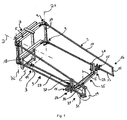
- FIG. 1 the device according to the invention for the application of fertilizers is shown schematically spatially.
- the device 1 has two arms 3, of which a boom 3 is mounted pivotably on a pivot frame 5 about a vertical axis A1.
- the second boom 3 is pivotally mounted on the pivot frame 5 about a vertical axis A2.
- Both arms 3 are identical, so that only one of the arms is provided with reference numerals.
- the booms 3 each have an upper and lower bearing section 9. Between the respective bearing sections 9 extends a vertical strut 17 forms a vehicle-proximal end of the boom 3.
- At the opposite end of the respective strut 17 of the respective arm 3 each have a second vertical strut 15 is arranged.
- the second vertical strut 15 and the first vertical strut 17 are formed substantially parallel to each other.
- the second vertical strut 15 is shorter than the first vertical strut 17, so that the boom 3 is formed overall trapezoidal.
- a lower horizontal strut 13 is oriented substantially horizontally, while an upper horizontal strut 11 is aligned sloping in the direction of the second vertical strut 15.
- the pivoting frame 5 is pivotally mounted on a support frame 7 about a horizontal axis, indicated by reference numeral D.
- the support frame 7 is on a (in FIG. 1 not shown) tanker attachable.
- the axis D extends substantially in the longitudinal direction of the tanker vehicle and substantially perpendicular to the axes A1 and A2.
- a receptacle 18, which can be coupled to a drawbar 27, is arranged on a region near the ground in the mounted state of the device. In FIG. 1 a drawbar 27 coupled thereto is shown.
- the drawbar 27 is pivotable about the vertical axis B relative to the support frame 7 of the device 1.
- the connection between receptacle 18 and drawbar 27 is arranged in an end portion 19 of the drawbar 27.
- a support section 21 is located at a distance from the end section of the drawbar.
- the support section 21 and the drawbar 27 are part of a support device 10.
- the support device 10 has a support wheel 29 in the support section 21.
- the support wheel 29 is mounted by means of an axis 31 in a wheel arch 33.
- the wheel arch 33 is arranged at an end of the drawbar 27 opposite the end section 19.
- On the wheel arch 33 a cross member 35 is arranged.
- two supports 23 are arranged on the cross member 35.
- the supports 23 are designed to receive a respective arm 3.
- FIG. 1 are the boom 3 in each case in the transport position and in engagement with the supports 23 and are supported by this.
- each case one or more locking elements 25 are arranged on the supports 23, which keep the horizontal strut 13 of the respective arm 3 locked in the transport position. Furthermore, at least one vertically aligned guide element 37 is formed on the supports in each case. The at least one guiding element 37 is designed for guiding in each case a height-adjusted arm 3 against unintentional lateral pivoting.
- the support device 10 is formed pivotable relative to the support frame 7 of the device about the horizontal axis C.
- Each of the two cantilevers 3 has an end portion 16 which is arranged opposite to the bearing of the respective cantilever.
- the boom 3 is arranged in each case in this end portion (not shown) for receiving an extension segment which can be pivoted back and forth between a transport position and an application position.
- FIG. 2 shows a top view of a device according to a preferred embodiment of the present invention, which is mounted on a tanker vehicle 100.
- the tanker 100 is located in FIG. 2 shown state in a cornering.
- the device 1 runs after the tanker 100 by the boom 3 are each supported by the support means 10 and held in the respective support 23.
- the cross member 35 is about an axis E (see FIG. 1 ) pivotally mounted on the wheel arch 33 and arranged parallel to a plane in which the axes are A1 and A2 of the boom 3. This plane is further formed parallel to the swing frame 5 and the support frame 7.
- the booms 3 are aligned parallel to one another, so that the support device 10 tracks the boom 3 parallelogram-like behind the vehicle 100.
- the pivotal movement of the device 1 in accordance with the support means 10 is also indicated by arrow 20.
- the drawbar 27 of the support device 10 is pivoted about the vertical axis B.
- the axis B, as in FIG. 2 shown in the same plane as the pivot axes A1 and A2.
- the vehicle 100 has a longitudinal axis which is substantially parallel to the axis D, about which the pivot arm 5 is pivotable relative to the support arm.
- FIGS. 3 and 4 the device 1 according to the invention is shown in side view.
- FIG. 3 shows the device 1 in a rear view (in the forward direction of travel of the vehicle) without vehicle 100.
- FIG. 4 shows a side projection of the Device off FIG. 3 with two indicated operating states. With regard to the extent identical reference numerals to the previous FIGS. 1 and 2 directed.
- FIGS. 3 and 4 is also the adjustability of the device 1 illustrated.
- the arms 3 of the device 1 are height-adjustable in the direction of the arrows 30 relative to the vehicle 100.
- the support wheel 29 stops on the ground, whereby the angle of the drawbar 27 relative to the axis C and the rest of the device 1 changed.
- the boom 3 are released from the position in their respective support 23 and moved along the guide 37 in height. After completed height adjustment, the boom 3 are pivoted from the transport position to the discharge position. Following or during this, the support means 10 is pivoted about the axis C in a substantially vertical position upwards.
- the support device 10 is thus approximated to the support frame 7 and the swing frame 5, so that the length of the composite vehicle 100 and device 1 (see FIG. 2 ) is minimized.
Landscapes
- Life Sciences & Earth Sciences (AREA)
- Soil Sciences (AREA)
- Engineering & Computer Science (AREA)
- Environmental Sciences (AREA)
- Water Supply & Treatment (AREA)
- Mechanical Engineering (AREA)
- Catching Or Destruction (AREA)
- Fertilizing (AREA)
Claims (15)
- Dispositif (1) pour l'épandage en bandes d'un engrais sur des surfaces agricoles utiles à l'aide de tuyaux flexibles, qui est conçu pour être monté à l'arrière d'un véhicule-citerne (100), avec deux flèches (3), qui peuvent pivoter avec un mouvement de va-et-vient autour d'un axe vertical (A1, A2) entre une position d'épandage et une position de transport, avec un dispositif d'appui (10) qui est disposé sur le dispositif (1) de manière pivotante autour d'un axe vertical (B) et conçu pour soutenir les flèches (3) dans la position de transport par rapport à la chaussée dans une portion d'appui (21) éloignée de l'axe (B), caractérisé en ce que le dispositif d'appui (10) est logé de manière pivotante dans la portion d'extrémité autour d'un axe horizontal (C) et est pivotant autour de l'axe horizontal (C) vers une position essentiellement verticale, lorsque les flèches (3) se trouvent hors de la position de transport.
- Dispositif (1) selon la revendication 1,
caractérisé en ce que le dispositif d'appui (10) comprend un timon de traction (27) qui est pivotant autour de l'axe vertical (B) et comprend dans la portion d'appui (21) une ou plusieurs roues d'appui (29) dont la direction de roulement est essentiellement parallèle à la direction de traction du timon de traction (27). - Dispositif (1) selon la revendication 1 ou 2,
caractérisé en ce que le dispositif d'appui (10) comprend, pour chacune des deux flèches (3), un support (23) pour la transmission des forces des flèches (3) vers une ou plusieurs des roues d'appui (29). - Dispositif (1) selon la revendication 3,
caractérisé en ce que les supports (23) des deux flèches (3) sont montés sur une traverse (35) qui est alignée parallèlement à un plan dans lequel les axes (A1, A2) des flèches (3). - Dispositif (1) selon l'une des revendications précédentes,
caractérisé en ce que les deux flèches (3) sont disposées essentiellement parallèlement l'un à l'autre. - Dispositif (1) selon l'une des revendications précédentes 3 à 5,
caractérisé en ce que les flèches (3) sont mobiles en hauteur à l'aide d'un dispositif de levage et peuvent être amenées dans la position de transport à l'aide d'un abaissement en contact avec le support (23) correspondant. - Dispositif (1) selon la revendication 6,
caractérisé en ce que les supports (23) comprennent chacun des éléments de blocage (25) avec lesquels les flèches (3) peuvent être amenées en emboîtement dans la position de transport à l'aide d'un abaissement. - Dispositif (1) selon l'une des revendications précédentes,
caractérisé en ce que les flèches (3) peuvent pivoter dans la position d'épandage autour d'un axe horizontal (D). - Dispositif (1) selon la revendication 8,
caractérisé en ce que les flèches (3) sont logées de manière pivotante autour de l'axe vertical (A1, A2) au niveau d'un châssis pivotant (5). - Dispositif (1) selon la revendication 9,
caractérisé en ce que le châssis pivotant (5) est logé de manière pivotante autour d'un axe horizontal (D) au niveau d'un châssis de support (7). - Dispositif (1) selon l'une des revendications 6 à 10,
caractérisé en ce que le dispositif de levage est disposé sur le véhicule-citerne (100) et le châssis de support (7) est conçu pour le montage sur le dispositif de levage du véhicule-citerne (100). - Dispositif (1) selon l'une des revendications 1 à 11,
caractérisé en ce que le dispositif de levage est disposé sur le châssis de support (7) et le châssis pivotant (5) est mobile en hauteur par rapport au châssis de support (7) à l'aide du dispositif de levage. - Dispositif (1) selon l'une des revendications précédentes,
caractérisé en ce que les flèches (3) comprennent chacune un segment de rallonge qui peut être pivoté avec un mouvement de va-et-vient entre une position de transport et une position d'épandage au niveau d'une portion d'extrémité de la flèche (16) correspondante. - Dispositif (1) selon l'une des revendications 4 à 13,
caractérisé en ce que la traverse (35) est conçue de manière réglable en hauteur. - Véhicule-citerne (100), plus particulièrement véhicule-citerne agricole, avec un dispositif (1) pour l'épandage en bandes d'un engrais sur des surfaces agricoles utiles à l'aide de tuyaux flexibles alimentés par des éléments de répartition, qui est monté à l'arrière d'un véhicule-citerne agricole (100),
caractérisé en ce que le dispositif (1) est conçu pour l'épandage en bandes d'un engrais selon l'une des revendications 1 à 14.
Priority Applications (1)
| Application Number | Priority Date | Filing Date | Title |
|---|---|---|---|
| PL11779184T PL2640178T3 (pl) | 2010-11-15 | 2011-11-07 | Urządzenie do nanoszenia pasami nawozu |
Applications Claiming Priority (2)
| Application Number | Priority Date | Filing Date | Title |
|---|---|---|---|
| DE202010015383U DE202010015383U1 (de) | 2010-11-15 | 2010-11-15 | Vorrichtung zum streifenförmigen Aufbringen von Düngemittel |
| PCT/EP2011/069528 WO2012065871A1 (fr) | 2010-11-15 | 2011-11-07 | Dispositif pour l'épandage d'engrais selon des bandes |
Publications (2)
| Publication Number | Publication Date |
|---|---|
| EP2640178A1 EP2640178A1 (fr) | 2013-09-25 |
| EP2640178B1 true EP2640178B1 (fr) | 2016-01-27 |
Family
ID=45832846
Family Applications (1)
| Application Number | Title | Priority Date | Filing Date |
|---|---|---|---|
| EP11779184.8A Not-in-force EP2640178B1 (fr) | 2010-11-15 | 2011-11-07 | Dispositif pour l'épandage d'engrais selon des bandes |
Country Status (6)
| Country | Link |
|---|---|
| US (1) | US8807451B2 (fr) |
| EP (1) | EP2640178B1 (fr) |
| CA (1) | CA2817807C (fr) |
| DE (1) | DE202010015383U1 (fr) |
| PL (1) | PL2640178T3 (fr) |
| WO (1) | WO2012065871A1 (fr) |
Families Citing this family (3)
| Publication number | Priority date | Publication date | Assignee | Title |
|---|---|---|---|---|
| DE202014001511U1 (de) | 2014-02-20 | 2015-05-21 | Hugo Vogelsang Maschinenbau Gmbh | Einbringvorrichtung für Mehrschichtdüngung |
| CN116216534A (zh) * | 2023-03-24 | 2023-06-06 | 浙江财经大学 | 一种提高桥梁建造安全的定朝向悬臂起重机 |
| CN116472836B (zh) * | 2023-05-04 | 2025-09-26 | 海南大学 | 环境信息采集装置、水肥一体化控制系统及控制方法 |
Family Cites Families (5)
| Publication number | Priority date | Publication date | Assignee | Title |
|---|---|---|---|---|
| DE4217375A1 (de) | 1992-05-26 | 1993-12-02 | Claas Saulgau Gmbh | Landwirtschaftliche Arbeitsmaschine, besonders Kreiselheuwender |
| DE20017937U1 (de) | 2000-10-19 | 2001-11-29 | Hugo Vogelsang Maschinenbau GmbH, 49632 Essen | Gestängevorrichtung für Verteilerfahrzeug |
| DE10339162B4 (de) * | 2003-08-26 | 2010-09-16 | Zunhammer, Sebastian, Dipl.-Ing. (FH) | Gülleausbringfahrzeug |
| DE202007011631U1 (de) * | 2006-12-11 | 2007-10-18 | Leeb Mechanik Gmbh | Aufhängevorrichtung für ein ausladendes landwirtschaftliches Anbaugerät |
| DE202008015564U1 (de) * | 2008-11-24 | 2009-02-19 | Zunhammer, Sebastian, Dipl.-Ing. (FH) | Gülleausbring-Vorrichtung |
-
2010
- 2010-11-15 DE DE202010015383U patent/DE202010015383U1/de not_active Expired - Lifetime
-
2011
- 2011-11-07 PL PL11779184T patent/PL2640178T3/pl unknown
- 2011-11-07 WO PCT/EP2011/069528 patent/WO2012065871A1/fr not_active Ceased
- 2011-11-07 US US13/885,197 patent/US8807451B2/en not_active Expired - Fee Related
- 2011-11-07 CA CA2817807A patent/CA2817807C/fr not_active Expired - Fee Related
- 2011-11-07 EP EP11779184.8A patent/EP2640178B1/fr not_active Not-in-force
Also Published As
| Publication number | Publication date |
|---|---|
| EP2640178A1 (fr) | 2013-09-25 |
| CA2817807A1 (fr) | 2012-05-24 |
| US8807451B2 (en) | 2014-08-19 |
| WO2012065871A1 (fr) | 2012-05-24 |
| CA2817807C (fr) | 2016-12-13 |
| DE202010015383U1 (de) | 2012-02-16 |
| PL2640178T3 (pl) | 2016-06-30 |
| US20130233214A1 (en) | 2013-09-12 |
Similar Documents
| Publication | Publication Date | Title |
|---|---|---|
| DD229572A5 (de) | Geraetetraeger mit mindestens einem seitenrahmen | |
| EP0679326B1 (fr) | Chariot trainé avec roues porteurs | |
| EP2660127B1 (fr) | Unité de châssis et unité de module pour un chariot tracteur | |
| DE9213091U1 (de) | Kreiselegge | |
| DE7338262U (de) | Landwirtschaftliche arbeitsmaschine | |
| DE2513413A1 (de) | Verfahren zur umwandlung eines geraeterahmens aus einem vorwaertsfahrenden erntebetriebszustand in einen seitwaertsfahrenden transportzustand | |
| EP3143861B1 (fr) | Faucheuse et attelage tracté et procédé de fonctionnement de la faucheuse | |
| EP2640178A1 (fr) | Dispositif pour l'épandage d'engrais selon des bandes | |
| DE1634764A1 (de) | Vorrichtung zum Verschwenken eines an ein Tragfahrzeug schwenkbar angeschlossenen,eventuell mit einem Bedienungssitz versehenen Tiefloeffels | |
| DE2622444A1 (de) | Anbauvorrichtung fuer landwirtschaftliche verteilmaschinen | |
| DE2319308C2 (de) | Maschine zum Ausbringen von verteilbarem Material | |
| EP1021943A2 (fr) | Epandeur agricole | |
| DE202005011305U1 (de) | Vorrichtung zur Seitenstabilisierung der Unterlenker einer Geräteanbauvorrichtung eines Ackerschleppers | |
| EP2371194B1 (fr) | Dispositif de répartition de semences et/ou d'engrais | |
| DE202011101157U1 (de) | Landwirtschaftliche Maschine | |
| DE102008062712A1 (de) | Mähwerk mit Querfördereinrichtung | |
| DE825639C (de) | Vorrichtung fuer Fahrzeuge, insbesondere Zugmaschinen, zur Verhuetung des Kippens bei Schwerpunktverlagerung | |
| DE3315813A1 (de) | Anbaubock fuer die dreipunkt-hebevorrichtung eines schleppers | |
| DE202020107319U1 (de) | Feldspritze | |
| EP1520462A2 (fr) | Véhicule d'épandage de lisier | |
| DE884881C (de) | Mit einem mittleren, zugleich angetriebenen und lenkbaren Vorderrad ausgebildeter Dreirad-Schlepper, besonders fuer die Landwirtschaft | |
| EP0381926A2 (fr) | Dispositif d'accouplement d'outils traînés, par exemple des remorques agricoles | |
| BE1026215B1 (de) | Verbindungsvorrichtung zum verbinden eines hubtransportwagens oder etwas entsprechendem mit einer zugmaschine | |
| DE1582169A1 (de) | Erntebergungsmaschine,insbesondere Feldhaecksler | |
| EP0158313A2 (fr) | Dispositif pour l'ameublissement du sous-sol adaptable sur véhicules agricoles et machines mobiles |
Legal Events
| Date | Code | Title | Description |
|---|---|---|---|
| PUAI | Public reference made under article 153(3) epc to a published international application that has entered the european phase |
Free format text: ORIGINAL CODE: 0009012 |
|
| 17P | Request for examination filed |
Effective date: 20130617 |
|
| AK | Designated contracting states |
Kind code of ref document: A1 Designated state(s): AL AT BE BG CH CY CZ DE DK EE ES FI FR GB GR HR HU IE IS IT LI LT LU LV MC MK MT NL NO PL PT RO RS SE SI SK SM TR |
|
| DAX | Request for extension of the european patent (deleted) | ||
| GRAP | Despatch of communication of intention to grant a patent |
Free format text: ORIGINAL CODE: EPIDOSNIGR1 |
|
| INTG | Intention to grant announced |
Effective date: 20150707 |
|
| GRAS | Grant fee paid |
Free format text: ORIGINAL CODE: EPIDOSNIGR3 |
|
| GRAA | (expected) grant |
Free format text: ORIGINAL CODE: 0009210 |
|
| AK | Designated contracting states |
Kind code of ref document: B1 Designated state(s): AL AT BE BG CH CY CZ DE DK EE ES FI FR GB GR HR HU IE IS IT LI LT LU LV MC MK MT NL NO PL PT RO RS SE SI SK SM TR |
|
| REG | Reference to a national code |
Ref country code: GB Ref legal event code: FG4D Free format text: NOT ENGLISH |
|
| REG | Reference to a national code |
Ref country code: CH Ref legal event code: EP |
|
| REG | Reference to a national code |
Ref country code: AT Ref legal event code: REF Ref document number: 772230 Country of ref document: AT Kind code of ref document: T Effective date: 20160215 |
|
| REG | Reference to a national code |
Ref country code: IE Ref legal event code: FG4D Free format text: LANGUAGE OF EP DOCUMENT: GERMAN |
|
| REG | Reference to a national code |
Ref country code: DE Ref legal event code: R096 Ref document number: 502011008802 Country of ref document: DE |
|
| REG | Reference to a national code |
Ref country code: LT Ref legal event code: MG4D |
|
| REG | Reference to a national code |
Ref country code: NL Ref legal event code: MP Effective date: 20160127 |
|
| PG25 | Lapsed in a contracting state [announced via postgrant information from national office to epo] |
Ref country code: NL Free format text: LAPSE BECAUSE OF FAILURE TO SUBMIT A TRANSLATION OF THE DESCRIPTION OR TO PAY THE FEE WITHIN THE PRESCRIBED TIME-LIMIT Effective date: 20160127 |
|
| PG25 | Lapsed in a contracting state [announced via postgrant information from national office to epo] |
Ref country code: ES Free format text: LAPSE BECAUSE OF FAILURE TO SUBMIT A TRANSLATION OF THE DESCRIPTION OR TO PAY THE FEE WITHIN THE PRESCRIBED TIME-LIMIT Effective date: 20160127 Ref country code: NO Free format text: LAPSE BECAUSE OF FAILURE TO SUBMIT A TRANSLATION OF THE DESCRIPTION OR TO PAY THE FEE WITHIN THE PRESCRIBED TIME-LIMIT Effective date: 20160427 Ref country code: GR Free format text: LAPSE BECAUSE OF FAILURE TO SUBMIT A TRANSLATION OF THE DESCRIPTION OR TO PAY THE FEE WITHIN THE PRESCRIBED TIME-LIMIT Effective date: 20160428 Ref country code: HR Free format text: LAPSE BECAUSE OF FAILURE TO SUBMIT A TRANSLATION OF THE DESCRIPTION OR TO PAY THE FEE WITHIN THE PRESCRIBED TIME-LIMIT Effective date: 20160127 |
|
| PG25 | Lapsed in a contracting state [announced via postgrant information from national office to epo] |
Ref country code: SE Free format text: LAPSE BECAUSE OF FAILURE TO SUBMIT A TRANSLATION OF THE DESCRIPTION OR TO PAY THE FEE WITHIN THE PRESCRIBED TIME-LIMIT Effective date: 20160127 Ref country code: RS Free format text: LAPSE BECAUSE OF FAILURE TO SUBMIT A TRANSLATION OF THE DESCRIPTION OR TO PAY THE FEE WITHIN THE PRESCRIBED TIME-LIMIT Effective date: 20160127 Ref country code: LT Free format text: LAPSE BECAUSE OF FAILURE TO SUBMIT A TRANSLATION OF THE DESCRIPTION OR TO PAY THE FEE WITHIN THE PRESCRIBED TIME-LIMIT Effective date: 20160127 Ref country code: IS Free format text: LAPSE BECAUSE OF FAILURE TO SUBMIT A TRANSLATION OF THE DESCRIPTION OR TO PAY THE FEE WITHIN THE PRESCRIBED TIME-LIMIT Effective date: 20160527 Ref country code: PT Free format text: LAPSE BECAUSE OF FAILURE TO SUBMIT A TRANSLATION OF THE DESCRIPTION OR TO PAY THE FEE WITHIN THE PRESCRIBED TIME-LIMIT Effective date: 20160527 Ref country code: LV Free format text: LAPSE BECAUSE OF FAILURE TO SUBMIT A TRANSLATION OF THE DESCRIPTION OR TO PAY THE FEE WITHIN THE PRESCRIBED TIME-LIMIT Effective date: 20160127 |
|
| REG | Reference to a national code |
Ref country code: DE Ref legal event code: R097 Ref document number: 502011008802 Country of ref document: DE |
|
| PG25 | Lapsed in a contracting state [announced via postgrant information from national office to epo] |
Ref country code: DK Free format text: LAPSE BECAUSE OF FAILURE TO SUBMIT A TRANSLATION OF THE DESCRIPTION OR TO PAY THE FEE WITHIN THE PRESCRIBED TIME-LIMIT Effective date: 20160127 Ref country code: EE Free format text: LAPSE BECAUSE OF FAILURE TO SUBMIT A TRANSLATION OF THE DESCRIPTION OR TO PAY THE FEE WITHIN THE PRESCRIBED TIME-LIMIT Effective date: 20160127 |
|
| REG | Reference to a national code |
Ref country code: FR Ref legal event code: PLFP Year of fee payment: 6 |
|
| PG25 | Lapsed in a contracting state [announced via postgrant information from national office to epo] |
Ref country code: RO Free format text: LAPSE BECAUSE OF FAILURE TO SUBMIT A TRANSLATION OF THE DESCRIPTION OR TO PAY THE FEE WITHIN THE PRESCRIBED TIME-LIMIT Effective date: 20160127 Ref country code: SK Free format text: LAPSE BECAUSE OF FAILURE TO SUBMIT A TRANSLATION OF THE DESCRIPTION OR TO PAY THE FEE WITHIN THE PRESCRIBED TIME-LIMIT Effective date: 20160127 Ref country code: SM Free format text: LAPSE BECAUSE OF FAILURE TO SUBMIT A TRANSLATION OF THE DESCRIPTION OR TO PAY THE FEE WITHIN THE PRESCRIBED TIME-LIMIT Effective date: 20160127 |
|
| PLBE | No opposition filed within time limit |
Free format text: ORIGINAL CODE: 0009261 |
|
| STAA | Information on the status of an ep patent application or granted ep patent |
Free format text: STATUS: NO OPPOSITION FILED WITHIN TIME LIMIT |
|
| 26N | No opposition filed |
Effective date: 20161028 |
|
| PG25 | Lapsed in a contracting state [announced via postgrant information from national office to epo] |
Ref country code: BE Free format text: LAPSE BECAUSE OF NON-PAYMENT OF DUE FEES Effective date: 20161130 Ref country code: BG Free format text: LAPSE BECAUSE OF FAILURE TO SUBMIT A TRANSLATION OF THE DESCRIPTION OR TO PAY THE FEE WITHIN THE PRESCRIBED TIME-LIMIT Effective date: 20160427 Ref country code: SI Free format text: LAPSE BECAUSE OF FAILURE TO SUBMIT A TRANSLATION OF THE DESCRIPTION OR TO PAY THE FEE WITHIN THE PRESCRIBED TIME-LIMIT Effective date: 20160127 |
|
| REG | Reference to a national code |
Ref country code: CH Ref legal event code: PL |
|
| PG25 | Lapsed in a contracting state [announced via postgrant information from national office to epo] |
Ref country code: LI Free format text: LAPSE BECAUSE OF NON-PAYMENT OF DUE FEES Effective date: 20161130 Ref country code: CH Free format text: LAPSE BECAUSE OF NON-PAYMENT OF DUE FEES Effective date: 20161130 |
|
| REG | Reference to a national code |
Ref country code: IE Ref legal event code: MM4A |
|
| PG25 | Lapsed in a contracting state [announced via postgrant information from national office to epo] |
Ref country code: LU Free format text: LAPSE BECAUSE OF NON-PAYMENT OF DUE FEES Effective date: 20161130 |
|
| REG | Reference to a national code |
Ref country code: FR Ref legal event code: PLFP Year of fee payment: 7 |
|
| PG25 | Lapsed in a contracting state [announced via postgrant information from national office to epo] |
Ref country code: IE Free format text: LAPSE BECAUSE OF NON-PAYMENT OF DUE FEES Effective date: 20161107 |
|
| REG | Reference to a national code |
Ref country code: AT Ref legal event code: MM01 Ref document number: 772230 Country of ref document: AT Kind code of ref document: T Effective date: 20161107 |
|
| PG25 | Lapsed in a contracting state [announced via postgrant information from national office to epo] |
Ref country code: AT Free format text: LAPSE BECAUSE OF NON-PAYMENT OF DUE FEES Effective date: 20161107 |
|
| REG | Reference to a national code |
Ref country code: BE Ref legal event code: MM Effective date: 20161130 |
|
| PG25 | Lapsed in a contracting state [announced via postgrant information from national office to epo] |
Ref country code: CY Free format text: LAPSE BECAUSE OF FAILURE TO SUBMIT A TRANSLATION OF THE DESCRIPTION OR TO PAY THE FEE WITHIN THE PRESCRIBED TIME-LIMIT Effective date: 20160127 Ref country code: HU Free format text: LAPSE BECAUSE OF FAILURE TO SUBMIT A TRANSLATION OF THE DESCRIPTION OR TO PAY THE FEE WITHIN THE PRESCRIBED TIME-LIMIT; INVALID AB INITIO Effective date: 20111107 |
|
| PG25 | Lapsed in a contracting state [announced via postgrant information from national office to epo] |
Ref country code: MK Free format text: LAPSE BECAUSE OF FAILURE TO SUBMIT A TRANSLATION OF THE DESCRIPTION OR TO PAY THE FEE WITHIN THE PRESCRIBED TIME-LIMIT Effective date: 20160127 Ref country code: MC Free format text: LAPSE BECAUSE OF FAILURE TO SUBMIT A TRANSLATION OF THE DESCRIPTION OR TO PAY THE FEE WITHIN THE PRESCRIBED TIME-LIMIT Effective date: 20160127 |
|
| PG25 | Lapsed in a contracting state [announced via postgrant information from national office to epo] |
Ref country code: MT Free format text: LAPSE BECAUSE OF FAILURE TO SUBMIT A TRANSLATION OF THE DESCRIPTION OR TO PAY THE FEE WITHIN THE PRESCRIBED TIME-LIMIT Effective date: 20160127 |
|
| PG25 | Lapsed in a contracting state [announced via postgrant information from national office to epo] |
Ref country code: TR Free format text: LAPSE BECAUSE OF FAILURE TO SUBMIT A TRANSLATION OF THE DESCRIPTION OR TO PAY THE FEE WITHIN THE PRESCRIBED TIME-LIMIT Effective date: 20160127 Ref country code: AL Free format text: LAPSE BECAUSE OF FAILURE TO SUBMIT A TRANSLATION OF THE DESCRIPTION OR TO PAY THE FEE WITHIN THE PRESCRIBED TIME-LIMIT Effective date: 20160127 |
|
| PGFP | Annual fee paid to national office [announced via postgrant information from national office to epo] |
Ref country code: FI Payment date: 20181120 Year of fee payment: 8 Ref country code: PL Payment date: 20181009 Year of fee payment: 8 Ref country code: CZ Payment date: 20181030 Year of fee payment: 8 Ref country code: DE Payment date: 20181204 Year of fee payment: 8 |
|
| PGFP | Annual fee paid to national office [announced via postgrant information from national office to epo] |
Ref country code: GB Payment date: 20181126 Year of fee payment: 8 Ref country code: FR Payment date: 20181127 Year of fee payment: 8 Ref country code: IT Payment date: 20181122 Year of fee payment: 8 |
|
| REG | Reference to a national code |
Ref country code: DE Ref legal event code: R119 Ref document number: 502011008802 Country of ref document: DE |
|
| REG | Reference to a national code |
Ref country code: FI Ref legal event code: MAE |
|
| PG25 | Lapsed in a contracting state [announced via postgrant information from national office to epo] |
Ref country code: FI Free format text: LAPSE BECAUSE OF NON-PAYMENT OF DUE FEES Effective date: 20191107 Ref country code: CZ Free format text: LAPSE BECAUSE OF NON-PAYMENT OF DUE FEES Effective date: 20191107 |
|
| GBPC | Gb: european patent ceased through non-payment of renewal fee |
Effective date: 20191107 |
|
| PG25 | Lapsed in a contracting state [announced via postgrant information from national office to epo] |
Ref country code: DE Free format text: LAPSE BECAUSE OF NON-PAYMENT OF DUE FEES Effective date: 20200603 Ref country code: GB Free format text: LAPSE BECAUSE OF NON-PAYMENT OF DUE FEES Effective date: 20191107 Ref country code: FR Free format text: LAPSE BECAUSE OF NON-PAYMENT OF DUE FEES Effective date: 20191130 Ref country code: IT Free format text: LAPSE BECAUSE OF NON-PAYMENT OF DUE FEES Effective date: 20191107 |
|
| PG25 | Lapsed in a contracting state [announced via postgrant information from national office to epo] |
Ref country code: PL Free format text: LAPSE BECAUSE OF NON-PAYMENT OF DUE FEES Effective date: 20191107 |