EP2640306B1 - Système d'implant dentaire et procédé pour la fabrication d'un système d'implant dentaire - Google Patents
Système d'implant dentaire et procédé pour la fabrication d'un système d'implant dentaire Download PDFInfo
- Publication number
- EP2640306B1 EP2640306B1 EP11807636.3A EP11807636A EP2640306B1 EP 2640306 B1 EP2640306 B1 EP 2640306B1 EP 11807636 A EP11807636 A EP 11807636A EP 2640306 B1 EP2640306 B1 EP 2640306B1
- Authority
- EP
- European Patent Office
- Prior art keywords
- coating
- connecting stud
- dental implant
- implant system
- region
- Prior art date
- Legal status (The legal status is an assumption and is not a legal conclusion. Google has not performed a legal analysis and makes no representation as to the accuracy of the status listed.)
- Active
Links
- 239000004053 dental implant Substances 0.000 title claims description 47
- 238000004519 manufacturing process Methods 0.000 title claims description 13
- 239000007943 implant Substances 0.000 claims description 80
- 238000000576 coating method Methods 0.000 claims description 70
- 239000011248 coating agent Substances 0.000 claims description 67
- 239000000463 material Substances 0.000 claims description 58
- 239000000919 ceramic Substances 0.000 claims description 37
- 238000000034 method Methods 0.000 claims description 12
- 238000005530 etching Methods 0.000 claims description 10
- 230000008569 process Effects 0.000 claims description 8
- RVTZCBVAJQQJTK-UHFFFAOYSA-N oxygen(2-);zirconium(4+) Chemical compound [O-2].[O-2].[Zr+4] RVTZCBVAJQQJTK-UHFFFAOYSA-N 0.000 claims description 7
- 239000011148 porous material Substances 0.000 claims description 7
- 229910001928 zirconium oxide Inorganic materials 0.000 claims description 7
- PNEYBMLMFCGWSK-UHFFFAOYSA-N Alumina Chemical compound [O-2].[O-2].[O-2].[Al+3].[Al+3] PNEYBMLMFCGWSK-UHFFFAOYSA-N 0.000 claims description 6
- 239000006185 dispersion Substances 0.000 claims description 4
- 239000002086 nanomaterial Substances 0.000 claims description 4
- SIWVEOZUMHYXCS-UHFFFAOYSA-N oxo(oxoyttriooxy)yttrium Chemical compound O=[Y]O[Y]=O SIWVEOZUMHYXCS-UHFFFAOYSA-N 0.000 claims description 4
- 238000010521 absorption reaction Methods 0.000 claims description 2
- XLYOFNOQVPJJNP-UHFFFAOYSA-N water Substances O XLYOFNOQVPJJNP-UHFFFAOYSA-N 0.000 claims description 2
- 229920002994 synthetic fiber Polymers 0.000 claims 3
- XAGFODPZIPBFFR-UHFFFAOYSA-N aluminium Chemical compound [Al] XAGFODPZIPBFFR-UHFFFAOYSA-N 0.000 claims 1
- 229910052782 aluminium Inorganic materials 0.000 claims 1
- 239000004411 aluminium Substances 0.000 claims 1
- 238000007373 indentation Methods 0.000 claims 1
- 125000006850 spacer group Chemical group 0.000 description 38
- 235000019589 hardness Nutrition 0.000 description 19
- 229910052751 metal Inorganic materials 0.000 description 12
- 239000002184 metal Substances 0.000 description 12
- 230000015572 biosynthetic process Effects 0.000 description 11
- 239000004033 plastic Substances 0.000 description 10
- 230000005540 biological transmission Effects 0.000 description 8
- 238000007788 roughening Methods 0.000 description 8
- 239000004696 Poly ether ether ketone Substances 0.000 description 7
- 239000002253 acid Substances 0.000 description 7
- 239000000853 adhesive Substances 0.000 description 7
- 230000001070 adhesive effect Effects 0.000 description 7
- 230000001055 chewing effect Effects 0.000 description 7
- 238000013461 design Methods 0.000 description 7
- 229920002530 polyetherether ketone Polymers 0.000 description 7
- 238000011282 treatment Methods 0.000 description 7
- RTAQQCXQSZGOHL-UHFFFAOYSA-N Titanium Chemical compound [Ti] RTAQQCXQSZGOHL-UHFFFAOYSA-N 0.000 description 6
- 229910010293 ceramic material Inorganic materials 0.000 description 6
- 229910052719 titanium Inorganic materials 0.000 description 6
- 239000010936 titanium Substances 0.000 description 6
- 230000008901 benefit Effects 0.000 description 5
- JUPQTSLXMOCDHR-UHFFFAOYSA-N benzene-1,4-diol;bis(4-fluorophenyl)methanone Chemical compound OC1=CC=C(O)C=C1.C1=CC(F)=CC=C1C(=O)C1=CC=C(F)C=C1 JUPQTSLXMOCDHR-UHFFFAOYSA-N 0.000 description 5
- 230000000694 effects Effects 0.000 description 5
- 230000002349 favourable effect Effects 0.000 description 5
- 230000007774 longterm Effects 0.000 description 5
- IJGRMHOSHXDMSA-UHFFFAOYSA-N Atomic nitrogen Chemical compound N#N IJGRMHOSHXDMSA-UHFFFAOYSA-N 0.000 description 4
- 238000005299 abrasion Methods 0.000 description 4
- 238000010276 construction Methods 0.000 description 4
- 238000001035 drying Methods 0.000 description 4
- 150000002500 ions Chemical class 0.000 description 4
- TWNQGVIAIRXVLR-UHFFFAOYSA-N oxo(oxoalumanyloxy)alumane Chemical compound O=[Al]O[Al]=O TWNQGVIAIRXVLR-UHFFFAOYSA-N 0.000 description 4
- 239000002245 particle Substances 0.000 description 4
- 238000010079 rubber tapping Methods 0.000 description 4
- 239000000470 constituent Substances 0.000 description 3
- 238000003780 insertion Methods 0.000 description 3
- 230000037431 insertion Effects 0.000 description 3
- 238000002360 preparation method Methods 0.000 description 3
- 230000001954 sterilising effect Effects 0.000 description 3
- 238000004659 sterilization and disinfection Methods 0.000 description 3
- 239000000126 substance Substances 0.000 description 3
- 230000003746 surface roughness Effects 0.000 description 3
- 230000008961 swelling Effects 0.000 description 3
- VYPSYNLAJGMNEJ-UHFFFAOYSA-N Silicium dioxide Chemical compound O=[Si]=O VYPSYNLAJGMNEJ-UHFFFAOYSA-N 0.000 description 2
- MCMNRKCIXSYSNV-UHFFFAOYSA-N Zirconium dioxide Chemical compound O=[Zr]=O MCMNRKCIXSYSNV-UHFFFAOYSA-N 0.000 description 2
- 230000002009 allergenic effect Effects 0.000 description 2
- 230000008859 change Effects 0.000 description 2
- 239000000460 chlorine Substances 0.000 description 2
- 238000002845 discoloration Methods 0.000 description 2
- 238000004090 dissolution Methods 0.000 description 2
- 229910000449 hafnium oxide Inorganic materials 0.000 description 2
- WIHZLLGSGQNAGK-UHFFFAOYSA-N hafnium(4+);oxygen(2-) Chemical compound [O-2].[O-2].[Hf+4] WIHZLLGSGQNAGK-UHFFFAOYSA-N 0.000 description 2
- 239000007769 metal material Substances 0.000 description 2
- 229910044991 metal oxide Inorganic materials 0.000 description 2
- 150000004706 metal oxides Chemical class 0.000 description 2
- 229910052757 nitrogen Inorganic materials 0.000 description 2
- 230000000737 periodic effect Effects 0.000 description 2
- 235000019592 roughness Nutrition 0.000 description 2
- 238000005488 sandblasting Methods 0.000 description 2
- 229910002076 stabilized zirconia Inorganic materials 0.000 description 2
- 238000002560 therapeutic procedure Methods 0.000 description 2
- 229920001169 thermoplastic Polymers 0.000 description 2
- 239000004416 thermosoftening plastic Substances 0.000 description 2
- 229910052727 yttrium Inorganic materials 0.000 description 2
- VWQVUPCCIRVNHF-UHFFFAOYSA-N yttrium atom Chemical compound [Y] VWQVUPCCIRVNHF-UHFFFAOYSA-N 0.000 description 2
- 241000894006 Bacteria Species 0.000 description 1
- OKTJSMMVPCPJKN-UHFFFAOYSA-N Carbon Chemical compound [C] OKTJSMMVPCPJKN-UHFFFAOYSA-N 0.000 description 1
- ZAMOUSCENKQFHK-UHFFFAOYSA-N Chlorine atom Chemical compound [Cl] ZAMOUSCENKQFHK-UHFFFAOYSA-N 0.000 description 1
- PXGOKWXKJXAPGV-UHFFFAOYSA-N Fluorine Chemical compound FF PXGOKWXKJXAPGV-UHFFFAOYSA-N 0.000 description 1
- 206010020751 Hypersensitivity Diseases 0.000 description 1
- 206010061218 Inflammation Diseases 0.000 description 1
- OAICVXFJPJFONN-UHFFFAOYSA-N Phosphorus Chemical compound [P] OAICVXFJPJFONN-UHFFFAOYSA-N 0.000 description 1
- NINIDFKCEFEMDL-UHFFFAOYSA-N Sulfur Chemical compound [S] NINIDFKCEFEMDL-UHFFFAOYSA-N 0.000 description 1
- 229910001069 Ti alloy Inorganic materials 0.000 description 1
- QCWXUUIWCKQGHC-UHFFFAOYSA-N Zirconium Chemical compound [Zr] QCWXUUIWCKQGHC-UHFFFAOYSA-N 0.000 description 1
- 238000004026 adhesive bonding Methods 0.000 description 1
- 230000007815 allergy Effects 0.000 description 1
- 229910045601 alloy Inorganic materials 0.000 description 1
- 239000000956 alloy Substances 0.000 description 1
- 238000005275 alloying Methods 0.000 description 1
- 229910002087 alumina-stabilized zirconia Inorganic materials 0.000 description 1
- QVGXLLKOCUKJST-UHFFFAOYSA-N atomic oxygen Chemical compound [O] QVGXLLKOCUKJST-UHFFFAOYSA-N 0.000 description 1
- 230000001580 bacterial effect Effects 0.000 description 1
- 229910052799 carbon Inorganic materials 0.000 description 1
- 229910052729 chemical element Inorganic materials 0.000 description 1
- 229910052801 chlorine Inorganic materials 0.000 description 1
- 239000000356 contaminant Substances 0.000 description 1
- 238000011109 contamination Methods 0.000 description 1
- RKTYLMNFRDHKIL-UHFFFAOYSA-N copper;5,10,15,20-tetraphenylporphyrin-22,24-diide Chemical compound [Cu+2].C1=CC(C(=C2C=CC([N-]2)=C(C=2C=CC=CC=2)C=2C=CC(N=2)=C(C=2C=CC=CC=2)C2=CC=C3[N-]2)C=2C=CC=CC=2)=NC1=C3C1=CC=CC=C1 RKTYLMNFRDHKIL-UHFFFAOYSA-N 0.000 description 1
- 238000005336 cracking Methods 0.000 description 1
- 238000013016 damping Methods 0.000 description 1
- 230000001419 dependent effect Effects 0.000 description 1
- 238000011161 development Methods 0.000 description 1
- 238000000635 electron micrograph Methods 0.000 description 1
- 239000004744 fabric Substances 0.000 description 1
- 229910052731 fluorine Inorganic materials 0.000 description 1
- 239000011737 fluorine Substances 0.000 description 1
- PCHJSUWPFVWCPO-UHFFFAOYSA-N gold Chemical compound [Au] PCHJSUWPFVWCPO-UHFFFAOYSA-N 0.000 description 1
- 239000010931 gold Substances 0.000 description 1
- 229910052737 gold Inorganic materials 0.000 description 1
- 230000035876 healing Effects 0.000 description 1
- 238000010438 heat treatment Methods 0.000 description 1
- 238000000265 homogenisation Methods 0.000 description 1
- 229910052739 hydrogen Inorganic materials 0.000 description 1
- 239000001257 hydrogen Substances 0.000 description 1
- 125000004435 hydrogen atom Chemical class [H]* 0.000 description 1
- 230000004054 inflammatory process Effects 0.000 description 1
- 238000013532 laser treatment Methods 0.000 description 1
- 239000007788 liquid Substances 0.000 description 1
- 230000007246 mechanism Effects 0.000 description 1
- 238000002844 melting Methods 0.000 description 1
- 230000008018 melting Effects 0.000 description 1
- 229910021645 metal ion Inorganic materials 0.000 description 1
- 239000000203 mixture Substances 0.000 description 1
- 229910052760 oxygen Inorganic materials 0.000 description 1
- 239000001301 oxygen Substances 0.000 description 1
- 230000035515 penetration Effects 0.000 description 1
- 229910052698 phosphorus Inorganic materials 0.000 description 1
- 239000011574 phosphorus Substances 0.000 description 1
- 229920001643 poly(ether ketone) Polymers 0.000 description 1
- 239000000843 powder Substances 0.000 description 1
- 239000002244 precipitate Substances 0.000 description 1
- 238000003825 pressing Methods 0.000 description 1
- 239000002994 raw material Substances 0.000 description 1
- 239000000376 reactant Substances 0.000 description 1
- 230000004044 response Effects 0.000 description 1
- 150000003839 salts Chemical class 0.000 description 1
- 238000007789 sealing Methods 0.000 description 1
- 229910052710 silicon Inorganic materials 0.000 description 1
- 239000010703 silicon Substances 0.000 description 1
- 239000000377 silicon dioxide Substances 0.000 description 1
- 238000005245 sintering Methods 0.000 description 1
- 239000007787 solid Substances 0.000 description 1
- 239000002904 solvent Substances 0.000 description 1
- 229910052717 sulfur Inorganic materials 0.000 description 1
- 239000011593 sulfur Substances 0.000 description 1
- 238000004381 surface treatment Methods 0.000 description 1
- 238000012360 testing method Methods 0.000 description 1
- 230000001225 therapeutic effect Effects 0.000 description 1
- 210000001519 tissue Anatomy 0.000 description 1
- 238000012546 transfer Methods 0.000 description 1
- WFKWXMTUELFFGS-UHFFFAOYSA-N tungsten Chemical compound [W] WFKWXMTUELFFGS-UHFFFAOYSA-N 0.000 description 1
- 229910052721 tungsten Inorganic materials 0.000 description 1
- 239000010937 tungsten Substances 0.000 description 1
- 239000011800 void material Substances 0.000 description 1
- 238000009736 wetting Methods 0.000 description 1
- RUDFQVOCFDJEEF-UHFFFAOYSA-N yttrium(III) oxide Inorganic materials [O-2].[O-2].[O-2].[Y+3].[Y+3] RUDFQVOCFDJEEF-UHFFFAOYSA-N 0.000 description 1
- 229910052726 zirconium Inorganic materials 0.000 description 1
Images

Classifications
-
- A—HUMAN NECESSITIES
- A61—MEDICAL OR VETERINARY SCIENCE; HYGIENE
- A61C—DENTISTRY; APPARATUS OR METHODS FOR ORAL OR DENTAL HYGIENE
- A61C8/00—Means to be fixed to the jaw-bone for consolidating natural teeth or for fixing dental prostheses thereon; Dental implants; Implanting tools
- A61C8/0012—Means to be fixed to the jaw-bone for consolidating natural teeth or for fixing dental prostheses thereon; Dental implants; Implanting tools characterised by the material or composition, e.g. ceramics, surface layer, metal alloy
- A61C8/0013—Means to be fixed to the jaw-bone for consolidating natural teeth or for fixing dental prostheses thereon; Dental implants; Implanting tools characterised by the material or composition, e.g. ceramics, surface layer, metal alloy with a surface layer, coating
-
- A—HUMAN NECESSITIES
- A61—MEDICAL OR VETERINARY SCIENCE; HYGIENE
- A61C—DENTISTRY; APPARATUS OR METHODS FOR ORAL OR DENTAL HYGIENE
- A61C8/00—Means to be fixed to the jaw-bone for consolidating natural teeth or for fixing dental prostheses thereon; Dental implants; Implanting tools
- A61C8/0012—Means to be fixed to the jaw-bone for consolidating natural teeth or for fixing dental prostheses thereon; Dental implants; Implanting tools characterised by the material or composition, e.g. ceramics, surface layer, metal alloy
-
- A—HUMAN NECESSITIES
- A61—MEDICAL OR VETERINARY SCIENCE; HYGIENE
- A61C—DENTISTRY; APPARATUS OR METHODS FOR ORAL OR DENTAL HYGIENE
- A61C13/00—Dental prostheses; Making same
- A61C13/0003—Making bridge-work, inlays, implants or the like
- A61C13/0006—Production methods
- A61C13/0007—Production methods using sand blasting
-
- A—HUMAN NECESSITIES
- A61—MEDICAL OR VETERINARY SCIENCE; HYGIENE
- A61C—DENTISTRY; APPARATUS OR METHODS FOR ORAL OR DENTAL HYGIENE
- A61C13/00—Dental prostheses; Making same
- A61C13/0003—Making bridge-work, inlays, implants or the like
- A61C13/0006—Production methods
- A61C13/0018—Production methods using laser
-
- A—HUMAN NECESSITIES
- A61—MEDICAL OR VETERINARY SCIENCE; HYGIENE
- A61C—DENTISTRY; APPARATUS OR METHODS FOR ORAL OR DENTAL HYGIENE
- A61C8/00—Means to be fixed to the jaw-bone for consolidating natural teeth or for fixing dental prostheses thereon; Dental implants; Implanting tools
- A61C8/0048—Connecting the upper structure to the implant, e.g. bridging bars
- A61C8/005—Connecting devices for joining an upper structure with an implant member, e.g. spacers
-
- A—HUMAN NECESSITIES
- A61—MEDICAL OR VETERINARY SCIENCE; HYGIENE
- A61C—DENTISTRY; APPARATUS OR METHODS FOR ORAL OR DENTAL HYGIENE
- A61C8/00—Means to be fixed to the jaw-bone for consolidating natural teeth or for fixing dental prostheses thereon; Dental implants; Implanting tools
- A61C8/0048—Connecting the upper structure to the implant, e.g. bridging bars
- A61C8/005—Connecting devices for joining an upper structure with an implant member, e.g. spacers
- A61C8/006—Connecting devices for joining an upper structure with an implant member, e.g. spacers with polygonal positional means, e.g. hexagonal or octagonal
-
- A—HUMAN NECESSITIES
- A61—MEDICAL OR VETERINARY SCIENCE; HYGIENE
- A61C—DENTISTRY; APPARATUS OR METHODS FOR ORAL OR DENTAL HYGIENE
- A61C8/00—Means to be fixed to the jaw-bone for consolidating natural teeth or for fixing dental prostheses thereon; Dental implants; Implanting tools
- A61C8/0048—Connecting the upper structure to the implant, e.g. bridging bars
- A61C8/005—Connecting devices for joining an upper structure with an implant member, e.g. spacers
- A61C8/0068—Connecting devices for joining an upper structure with an implant member, e.g. spacers with an additional screw
-
- A—HUMAN NECESSITIES
- A61—MEDICAL OR VETERINARY SCIENCE; HYGIENE
- A61C—DENTISTRY; APPARATUS OR METHODS FOR ORAL OR DENTAL HYGIENE
- A61C8/00—Means to be fixed to the jaw-bone for consolidating natural teeth or for fixing dental prostheses thereon; Dental implants; Implanting tools
- A61C8/0048—Connecting the upper structure to the implant, e.g. bridging bars
- A61C8/005—Connecting devices for joining an upper structure with an implant member, e.g. spacers
- A61C8/0069—Connecting devices for joining an upper structure with an implant member, e.g. spacers tapered or conical connection
-
- A—HUMAN NECESSITIES
- A61—MEDICAL OR VETERINARY SCIENCE; HYGIENE
- A61C—DENTISTRY; APPARATUS OR METHODS FOR ORAL OR DENTAL HYGIENE
- A61C8/00—Means to be fixed to the jaw-bone for consolidating natural teeth or for fixing dental prostheses thereon; Dental implants; Implanting tools
- A61C8/0018—Means to be fixed to the jaw-bone for consolidating natural teeth or for fixing dental prostheses thereon; Dental implants; Implanting tools characterised by the shape
- A61C8/0022—Self-screwing
-
- A—HUMAN NECESSITIES
- A61—MEDICAL OR VETERINARY SCIENCE; HYGIENE
- A61C—DENTISTRY; APPARATUS OR METHODS FOR ORAL OR DENTAL HYGIENE
- A61C8/00—Means to be fixed to the jaw-bone for consolidating natural teeth or for fixing dental prostheses thereon; Dental implants; Implanting tools
- A61C8/0086—Means to be fixed to the jaw-bone for consolidating natural teeth or for fixing dental prostheses thereon; Dental implants; Implanting tools with shock absorbing means
-
- Y—GENERAL TAGGING OF NEW TECHNOLOGICAL DEVELOPMENTS; GENERAL TAGGING OF CROSS-SECTIONAL TECHNOLOGIES SPANNING OVER SEVERAL SECTIONS OF THE IPC; TECHNICAL SUBJECTS COVERED BY FORMER USPC CROSS-REFERENCE ART COLLECTIONS [XRACs] AND DIGESTS
- Y10—TECHNICAL SUBJECTS COVERED BY FORMER USPC
- Y10T—TECHNICAL SUBJECTS COVERED BY FORMER US CLASSIFICATION
- Y10T29/00—Metal working
- Y10T29/49—Method of mechanical manufacture
- Y10T29/49567—Dental appliance making
Definitions
- the invention relates to a dental implant system having a first implant part intended for insertion into a jawbone and having a second implant part assigned thereto for attachment of a tooth replacement piece, wherein the implant parts are integrally formed on one of the implant parts. can be mechanically connected to one another in a receiving channel provided in the other implant portion receiving connector.
- dental implants can be used as part of the reconstructive therapy. They are usually used instead of an extracted or failed tooth in the jaw bone to hold there after a healing period of about four to twelve weeks serving as a denture prosthetic part or a crown.
- a dental implant is usually formed as a suitably shaped metal body, which is inserted by screwing at the intended location in the jawbone.
- the dental implant usually has at the apical end a mostly self-tapping screw thread with which the dental implant is inserted into the correspondingly prepared implant bed.
- dental implant systems can be designed in several parts.
- a basically two-part construction can be provided, the dental implant system being a first implant part, also designated as an actual implant or post part, for insertion into the jawbone and, in addition to this, an associated second, also referred to as abutment part second implant part comprises, to which in turn provided as a prosthesis or the like tooth replacement piece can be attached.
- the first implant part or post part is usually provided on its outer side with a thread, which can be designed as a self-tapping or not as a self-tapping thread.
- the post part is usually anchored in a correspondingly prepared implant bed of the jawbone.
- the design of the provided in the outer region of the dental implant thread is usually designed for a high primary stability of the arrangement and a uniform transmission of the forces occurring in the chewing load of the dental implant forces in the jawbone.
- connection pin which is integrally formed on one of the implant parts, as a rule on the abutment part, is usually provided. This can be inserted into a receiving channel provided in the other implant part, as a rule in the post part.
- the connecting pin on the one hand and the receiving channel on the other hand are usually adapted to each other so that with a relatively simple mountability still good guidance of the components into one another and thus a sufficiently high mechanical stability can be achieved.
- the body part which is usually equipped at its upper portion with a crown, another prosthetic restoration or the like in a conventional manner, can be glued to the mechanical connection with the post part via the inserted into the receiving channel connecting pin with the post part.
- the body part can also be pressed into the post part and fixed only by jamming, or else additionally fixed by cementing or gluing.
- the dental implant when screwing the body part and especially later in chewing mechanically extremely heavily loaded, so that an adhesive bond of the type mentioned may not have sufficiently high mechanical stability just in view of the desired very long residence time in the patient's mouth.
- the body part can also be screwed to the post part via a suitably chosen connecting screw.
- the thread of the connecting screw When inserting the thread of the connecting screw is usually screwed into an associated internal thread in the post part.
- the screw head of the connecting screw presses it against the dental implant via a countersink of the abutment part.
- Such multi-part dental implant systems with a screw connection between the mounting part and post part for example, from DE 10 2006 018 726 A1 or the DE 10 2008 054 138 A1 known.
- the first implant part or post part and likewise the second implant part or head or mounting part usually consist of a suitably chosen metal, in particular of titanium or a titanium alloy.
- a suitably chosen metal in particular of titanium or a titanium alloy.
- This choice of materials provides acceptable tolerability for the patient and good biocompatibility.
- implant systems manufactured on this material basis have a high long-term stability with low susceptibility to fractures.
- titanium is widely used as a raw material for implant systems and also enjoys extensive scientific acceptance, especially since the sterilization required for use within the reconstructive therapy can be ensured comparatively easily and reliably.
- the material costs are also limited, so that comparatively large numbers of implant systems can be produced on this basis usually with acceptable cost.
- a multi-part implant system based on titanium, in which an elastic sealing element is provided in the connecting region between the post and body part to compensate for gaps, is from the CH 696 625 A5 known.
- an allergenic potential may not be excluded in such metal-based implant systems. Allergies to metals are usually caused by the formation of metal ions. In addition, there is the danger that inflammatory reactions in the patient's mouth could be caused by particles separated from the implant, for example by flaking off the implant surface or by abrasion in multi-part systems.
- the intrinsic color of the metallic implant components can have an aesthetically and / or optically disturbing influence, and the electrical conductivity of the metal components can lead to disturbing effects.
- Ceramics are particularly suitable as the base material for implants, usually based on zirconium oxide (preferably yttria or alumina stabilized), or zirconium-containing alloys, zirconia-alumina ceramics or ceramics containing either zirconia or alumina or at least one of the ceramics as a main component.
- ceramics can be used, which are based on silicon or silica and z. As admixtures of nitrogen, hydrogen, carbon or tungsten include. Ceramic implant systems have the general advantage of high biocompatibility and thus good compatibility, the allergenic potential is extremely low.
- the surface is largely unfavorable for bacterial growth, so that such implants in their entirety are particularly favorable for long-term applications and long residence times in the patient's mouth.
- almost no gray discoloration occurs in the surrounding tissue, so that particularly high-quality aesthetic effects can be achieved.
- Ceramic-based dental implants are currently known essentially only in one-piece design.
- the material properties of the ceramic components eg brittle, high hardness, low to no ductility
- material hardnesses according to Vickers
- material hardnesses according to Vickers
- a dental implant system of the above-mentioned type based on ceramics, whose connecting pin has in its contact region to the receiving channel a coating forming an elastic element, wherein the surface of the connecting pin to form a material connection with this elastic element is made porous, is known from EP 0 015 599 A1 known.
- this system has only an insufficient mechanical stability with respect to the forces occurring during a chewing load.
- the invention is therefore based on the object to provide a - preferably two- or multi-part executed - implant system of the type mentioned above, which also with the use of ceramic or their basic material properties comparable base materials for at least one of the implant parts a special stability and long service life allows. Furthermore, a particularly suitable manufacturing method for the implant system should be specified.
- the connecting pin is made of a material having a hardness of at least 500, preferably of at least 750, more preferably of at least 1000, and has in a contact region to the receiving channel on its surface one of a softer compared to the material of the connecting pin material, in particular with a hardness of at most 25, preferably of at most 20, more preferably at most 15, formed coating with a layer thickness of at most 0.3 mm, preferably as a spacer on.
- the coating surface area porous preferably having a porosity of at least 0.1, carried out with the surface of the connecting pin in the region of the material connection with coating a r a - Value of at most 10%, preferably of at most 5%, the coating thickness of the coating.
- the average roughness of the surface is advantageously at most 10% of the layer thickness of the coating.
- the stated hardness values are to be understood as hardness values according to Vickers on the basis of a test force of 10 kiloponds in accordance with DIN, ie the said hardness value of 500 corresponds, for example, to a standard specification of 500 HV 10.
- the invention is based on the consideration that in multi-part implant systems a high stability and longevity can be achieved if the forces occurring in the chewing processes are taken into account in a suitable manner. Especially in the transmission of these forces in multi-part dental implant systems from Body part in the anchored in the jaw bone post part should be ensured a largely material-friendly power transmission. This is particularly achievable by consistently making a planar contact while largely avoiding localized contact points between the implant parts. In contrast to metal-based systems, in which such surface contact almost automatically occurs due to the higher elastic deformability and the ductility of the material in response to the applied forces, the surface contact in ceramic-based systems could be due to the lack of ductility of the material and be insufficient in view of almost necessarily existing manufacturing tolerances and inaccuracies.
- an additional element is now provided in the structure of the dental implant system which, in the manner of a compensating body, is intended to prevent the formation of local, point contact points between the implant parts.
- the spacer provided for this purpose should be predetermined with regard to its choice of material in such a way that-due to suitable ductility-it produces a suitable compensation in the intermediate space between the implant parts and thus ensures a flat force transmission between the components.
- the material of the spacer should be chosen correspondingly softer and thus deformable than the material of the actual implant parts.
- the spacer could be designed as a braid by materially bonded to it, that is, for example glued or fused, material threads so that it is present in particular in the form of a net-like coating.
- a reliable adjustment of a suitable possibly due to production occurring surface roughness of the contact surfaces balancing minimum distance between the contact surfaces possible
- suitable for a material intake volumes are formed.
- These are particularly suitable for absorbing excess material, such as adhesive or the like.
- spacers considered inventive is thus particularly suitable for bonding the implant parts together.
- the spacer is designed as applied to the surface of the connecting pin coating.
- the coating may be partially or web-like mounted on the surface of the connecting pin, but is advantageously carried out continuously and over the entire surface. This results in a full-surface design of the spacer on the connecting pin.
- the spacer for bonding the implant parts together as well as for the preparation of a connection by screwing since the spacer in this case can then also cause a damping in the power transmission between the screwed together implant parts.
- the spacer is positively connected, ie in particular as a coating or glued or fused element, connected to the connecting pin.
- the spacer may also be applied in the manner of an inner coating on the inside of the receiving channel, so that it is also positioned after mounting the implant parts in the connecting region of the implant parts with each other between them.
- a combination of two spacers, ie one on each of the two implant parts, is also possible.
- the cohesive connection of the spacer with the connecting pin executed particularly intimately.
- the connecting pin has a roughened and / or porous surface in the region of its connection to the spacer or in the region of the coating.
- the porosity of the surface is designed such that a porous surface arises precisely in the region of the cohesive connection of the connecting pin with the coating, preferably with a porosity having a structure size of at most one micrometer, alternatively or additionally preferably with a porosity of at least 0.1.
- a porous surface is ensured that just in combination with a suitable choice of material for the coating whose material can penetrate at least partially into the porosity-related cavities present in the surface and thus creates a particularly intimate bond.
- the porosity is a dimensionless measurand. It represents the ratio of void volume to total volume of a substance or mixture of substances and is defined as 1 minus the quotient of bulk density of a solid and pure density.
- the intended roughening is advantageously applied to the surface after the actual production, ie in particular within the scope of an additional treatment step.
- the roughening can be carried out, for example, mechanically (for example by irradiation, for example by sandblasting), chemically (for example by etching) or by irradiation with a laser, preferably with a femtosecond laser.
- a laser which has a pulse duration of less than about 1 ps, can also targeted structures or pattern structure be applied to the surface to be coated, which also still a deeper damage to the underlying material, ie in particular the ceramic can be avoided.
- the connecting pin advantageously has, in cross section, an outer contour adapted to the contour of the associated receiving channel. Seen in the longitudinal direction of the connecting pin or receiving channel, both can also be designed with a constant cross-section, that is, for example, with a cylindrical base body.
- the cross-sections taper in the direction of the free end of the connecting pin, in a particularly advantageous embodiment in a conical design, so that in a particularly simple manner good adhesion and high tightness can be achieved.
- the outer contour of the connecting pin - and adapted accordingly the receiving channel in its inner contour - in cross-section at least partially or in sections a multiple symmetry.
- the spacer is advantageously dimensioned such that, on the one hand, excessive flexibility and deformability of the assembled overall system due to excessive layer thickness are avoided and, on the other hand, reliable compensation of surface roughness and manufacturing tolerances is ensured.
- the fact is also preferably taken into account that just with conical connections between the body part and the post part, the elastic deformability of the post part is used to compensate for production-related angle tolerances with respect to the cone angle.
- the angle tolerances are usually dimensioned in this way, the cone angle of the mold cavity in the post part is smaller than the cone angle of the contact pin formed on the body part.
- total length, diameter of the post part, etc. has a layer thickness of at least 0.001 mm, preferably at least 0.05 mm, more preferably at least 0.01 mm, and / or of at most 0.3 mm, preferably at most 0.2 mm, particularly preferably at most 0.1 mm.
- the respective components, in particular the implant parts are advantageously selected in view of a high long-term stability, especially in the intended operating environment, and also with regard to particularly good compatibility and biocompatibility.
- a suitably chosen metal preferably gold, which is sufficiently soft, in particular with regard to the choice of material of the actual implant parts, could be selected for the spacer.
- the spacer made of a plastic, preferably made of a high-strength thermoplastic from the group of polyether ketones, in particular polyetheretherketone, also known as PEEK produced.
- PEEK usually has a hardness of Vickers of about 12 and thus fulfills the now proposed design criterion particularly satisfactory.
- the plastic forming the spacer has a modulus of elasticity of at least 1000 MPa.
- the spacer is sufficiently hard to withstand the forces occurring during chewing, so that a plastic deformation and a "swelling" of the material are avoided.
- the distance-holder plastic forming in additional or alternative advantageous embodiment, a water absorption of at most 1% , preferably of at most 0.5%, more preferably of at most 0.2%.
- the components of the implant system are advantageously designed for easy sterilization.
- the plastic forming the spacer advantageously has a softening temperature of at least 140 ° C., preferably of at least 160 ° C., more preferably of 300 ° C., so that standard superheated steam sterilizations are carried out without restriction (usually at a temperature of 134 ° C.) can be made once or several times as needed.
- the connecting pin is preferably formed of a ceramic, in particular of zirconium oxide, so that overall a high stability of the system is ensured.
- a ceramic connecting pin with applied surface coating is particularly advantageous for use in combination with a post part or receiving channel made of titanium or other metallic material, since basically in the material pairing ceramic / metal, especially ceramic / titanium, due to the significantly greater hardness of Ceramic with metal abrasion and corresponding surface and color changes must be expected.
- the mentioned ceramic usually has a hardness according to Vickers ("Vickers hardness", HV) of more than 1000 on. Since the mentioned effects occur already amplified with ceramics having a Vickers hardness of 500 or more, the spacer provided as an intermediate or buffer element is already particularly advantageous for this reason.
- the mentioned effects, in particular the surface abrasion can be effectively avoided in particular by the surface coating acting as a spacer between ceramic on the one hand and metal, in particular titanium, on the other hand.
- a total of one ceramic, in particular zirconium oxide or aluminum oxide, is used for the implant parts, in any case as the main component, as a result of which a metal-free basic body is provided.
- Such materials are characterized by their excellent biocompatibility and provide a bacteria-resistant surface.
- the connecting pin made of yttrium and / or alumina-stabilized zirconia is carried out, wherein in a further advantageous embodiment, the surface of the connecting pin in the region of the material connection with the spacer a depletion zone with a reduced compared to the inner volume of the connecting pin yttrium or aluminum oxide content.
- a ceramic base body may preferably be treated by means of laser treatment and / or in a liquid and / or gaseous medium, preferably in an acid bath, wherein the acid bath is mixed with ions, each consisting of an element from one of the V. to VII. Main Group of the Periodic Table of the Elements or include such an element as a component.
- ions each consisting of an element from one of the V. to VII. Main Group of the Periodic Table of the Elements or include such an element as a component.
- this process leads to the formation of surface structures which ensure particularly favorable wetting properties and to the use of the ceramic body as a carrier body for the spacer allow a particularly good adhesion of the intended as a spacer coating.
- the treatment of the ceramic base body in the manner of the etching and in particular the intercrystalline etching namely forms a specific nanostructure on the surface.
- a multiplicity of comparatively smaller pores or depressions having a mean extent in the sub-micron range, preferably less than 500 nm and in particular less than 250 nm, are to be found.
- Such structures can be detected for example by means of electron micrographs.
- the surface is characterized in particular by the fact that the depth of the nanostructure, ie the depth of the thereby obtainable pores, is greater than the structure width, ie the characteristic lateral extent of the structures achieved.
- the intended porosity of the surface is thus provided with particularly favorable for the desired high-strength cohesive connection properties.
- the ratio in the nanostructure between the structure depth and the structure width is greater than 1: 1, advantageously greater than 1.5: 1 and in particular greater than 2: 1.
- the advantageously provided depletion zone in the surface region which ultimately brings about the desired structure and the desired properties in the connection with the material of the spacer, in particular by selective or at least selectively accelerated dissolution of individual components such as chemical elements and / or oxides from the surface, preferably by a suitably selected etching process.
- Such favorable structures can be created, in particular, by detaching individual elements and / or individual metal oxides (zirconium oxide, aluminum oxide, yttrium oxide, hafnium oxide, etc.) present in the ceramic, in particular yttrium oxide and hafnium oxide, from the surface.
- a depletion zone of these metal oxides is formed on and / or in the vicinity of the surface near the surface.
- the ratio between the tetragonal and the monoclinic phase in the stabilized zirconia has changed.
- the proportion of the monoclinic phase in the surface could be increased or reduced by at least 0.1%, advantageously to or more than 0.5% and in particular to or by more than 1.5% by such a method become. Since the surface is pressurized by the lower density of the monoclinic phase, the initial crack formation is inhibited in this way, so that an increase in the initial strength can be expected.
- the preparation of the intended depletion zone in the surface of the ceramic body can be carried out in particular by an etching process in a suitably selected acid bath.
- the envisaged reactants for the ceramic of the main body ie the ions with constituents from the fifth to seventh main group of the Periodic Table of the Elements, can act in particular as salt formers for the respective metal.
- the acid bath may comprise ions consisting of or comprising as constituents nitrogen (N), oxygen (O), fluorine (F), chlorine (Cl), sulfur (S) and / or phosphorus (P).
- N nitrogen
- O oxygen
- F fluorine
- Cl chlorine
- S sulfur
- P sulfur
- the stated object is achieved by roughening the connecting pin on its surface prior to the production of the integral connection with the spacer in the region of the intended connection with the spacer.
- the roughening can be made in an advantageous embodiment by laser irradiation or by sandblasting.
- the connecting pin is made porous on its surface in the region of the intended connection with the spacer on the surface before the bonded connection with the spacer is produced, preferably by means of an etching process.
- a coating provided for forming the spacer on the connecting pin is advantageously applied to this a dispersion, which is then dried.
- the dispersion advantageously provided for the formation of the coating particles are held with a particle size of up to 20 microns in solution.
- the dispersion can then be sprayed on or otherwise applied in a suitable manner, in which case advantageously a drying step at a drying temperature of, for example, about 150 ° C. can take place.
- a drying step at a drying temperature of, for example, about 150 ° C. can take place.
- the solvent components are volatilized, so that the material particles precipitate and thus form the coating.
- the drying is preferably carried out in vacuo or under reduced pressure, so that the formation of air inclusions is kept particularly low. In particular, since such air pockets could block the entry of the material into the surface pores of the carrier body, in this way an intimate cohesive connection is particularly favored.
- a heat treatment of the provided with the coating connection pin at a treatment temperature above the softening temperature of the coating material preferably of at least 350 ° C, more preferably of at least 400 ° C.
- a treatment temperature above the softening temperature of the coating material preferably of at least 350 ° C, more preferably of at least 400 ° C.
- This can be done in the manner of melting the applied material, a homogenization, wherein optionally at the same time a penetration of the coating material is promoted in surface pores or roughnesses in the connecting pin.
- a treatment is particularly favorable and effective for layer thicknesses up to about 0.1 mm.
- a powder coating could be provided for layer thicknesses greater than 0.1 mm.
- the advantages achieved by the invention are, in particular, that inaccuracies and manufacturing tolerances in the components can be compensated for by the spacers provided in the connecting region of connecting pin and receiving channel, so that even when using ceramic materials for the connecting pin or the implant parts as a whole Contact between These parts can be produced. In this way, even with regard to the high chewing forces occurring, a material-sparing and reliable forwarding of the forces is possible, so that the use of the ceramic materials which are in themselves desirable is also possible in multi-part dental implant systems.
- a porosity of at least 0.1, provided at least in the surface area is particularly advantageous in order to be able to apply an adhesive coating of a plastic, in particular PEEK.
- the advantages of a plastic-based coating on a ceramic base body are in particular the change in the chemical properties and in particular the acid resistance. With regard to the mechanical property changes, in particular the optimized introduction of force / force transmission must be mentioned. But even the change of the coefficient of friction p by means of an adhesive coating provides ceramic materials significant advantages in the applicability, especially in comparison to other metallic materials.
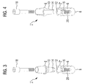
- the dental implant system 1, 1 ', 1 "according to the FIG. 1 to 4 is intended for use in the jawbone instead of an extracted or failed tooth to hold there as a prosthetic prosthetic part or a crown.
- the dental implant system 1, 1 ', 1 " is designed in several parts and comprises a first implant part 2, 2', 2" designed as a post part and an associated therewith, provided for attachment of a dental prosthesis, also referred to as an abutment second implant part 4.
- the first implant part 2, 2 ', 2 "or post part is externally provided with an external thread 6, which is configured in particular as a self-tapping screw thread at the apical end 8.
- the first implant part 2, 2 ', 2 "or post part are inserted by screwing at the intended location in the jawbone.
- a Connecting pin 10 is formed, which in an associated, in the first implant part 2, 2 ', 2 "provided receiving channel 12 can be inserted.
- the connecting pin 10 By inserting the connecting pin 10 in the receiving channel 12 creates a mechanical connection of the implant parts 2, 4 with each other.
- the connecting pin 10 is adapted in its outer contour to the inner contour of the receiving channel 12, both seen conically in the longitudinal direction may be formed (embodiment according to FIG. 2 ).
- the outer contour of the connecting pin 10 - and adapted accordingly the inner contour of the receiving channel 12 - be configured in cross-section with a multiple (sechtronn in the embodiment) symmetry, so that upon assembly of said components, a rotational locking occurs and thus a reliable rotational alignment of the Upbuilding part can be adjusted relative to the post part.
- 4 is for this purpose an indexing or for the formation of a rotary locking end of the connecting pin 10 an indexing element 14, in turn, a cross-section with multiple symmetry arranged, which engages in the mounted state in a corresponding, associated end channel piece 16 in the receiving channel 12.
- the dental implant systems 1, 1 ', 1 "in the embodiments according to FIG. 1 to 4 are each carried out for a screw connection of the implant parts 2, 4 with each other.
- a connecting screw 18 is provided, which engages in a screw thread 20 provided in each case within the first implant part 2, 2 ', 2 ".
- the implant parts 2, 4 are suitably adapted to the intended use and basically made of ceramic material such as zirconium oxide or aluminum oxide.
- 10 yttrium-stabilized zirconia is selected as the material for the connecting pin.
- This has a comparatively high hardness of 1500 + - 100 according to Vickers ("Vickers hardness", HV). Because of the low elasticity and the lack of plastic deformability of such a hard material, however, it is to be assumed that a planar contact of the implant parts 2, 4 with each other does not exist in the region of the connecting pin 10. Especially in the transmission of comparatively large chewing forces so punctual loads in the contact area of the implant parts 2, 4 may occur.
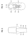
- the connecting pin 10 is provided with a coating 26 in a contact area to the receiving channel 12 on its surface 24, such as this in the cross-sectional drawing according to FIG. 5 is shown.
- a coating 26 is provided that it should be made of a material compared to the material of the connecting pin 10 significantly softer material with a hardness (according to Vickers) of at most 25.
- the coating 26-due to suitable ductility -produces a suitable compensation in the intermediate space between the implant parts 2, 4, so that a planar force transmission between the components is ensured.
- the coating 26 is made of a plastic, namely from the high-strength thermoplastic polyetheretherketone, also known as PEEK.
- PEEK usually has a hardness of Vickers of about 12 and thus fulfills the now proposed design criterion particularly satisfactory.
- the coating 26 may be alternatively or additionally arranged on the inner surface 28 of the receiving channel 12 in the post part 2 or second implant part 4 with the same effect, as shown in the cross-sectional drawing in FIG. 6 is shown.
- the coating 26 provided for the formation of the spacer 22 is implemented continuously in the manner of a full-area coating.
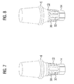
- it may also comprise, in the manner of a net, braid or the like enclosing the connecting pin 10, a plurality of sub-elements or partial coatings 30, which form a net-like structure to form gaps 32 (FIG. FIG. 7 ) or independently ( FIG. 8th ) in each case cohesively with the connecting pin 10 - or at the inside mounting to the inner surface of the receiving channel 12 - are connected.
- connection system is thus particularly suitable for an adhesive connection of the implant parts 2, 4 with each other.
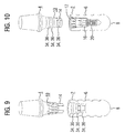
- This formation of receiving chambers for excess adhesive can be promoted even further by using the other component - in FIG. 9 shown for the receiving channel 12 and in FIG. 10 shown for the connecting pin 10 - mechanically further receiving chambers 34, in the embodiment according to FIG. 9, 10 in the form of additionally mounted circumferential grooves 36, are provided.
- an intimate cohesive connection between the connecting pin 10 and the inner surface 28 of the receiving channel 12 on the one hand and the spacer 22 forming coating 26 on the other hand provided.
- the surface of the connecting pin 10 is roughened in the region of the coating and / or made porous.
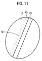
- FIG. 11 is shown schematically in enlarged detail causes the roughening or porosity in the surface region, in particular of the respective ceramic component, that a plurality of small material chambers 38 are formed, in which the relatively soft, the coating 26 forming material can penetrate. This results in the desired intimacy of the cohesive connection, so that the coating 26 adheres particularly firmly to the surface carrying it.
- the said porosity or roughening of the surface can be achieved by a particularly suitable method, for example by - possibly material-specific - etching, by targeted setting of a depletion zone of a material or a crystallographic parameter or the like can be produced.
- connection pin 10 In the partially enlarged view in FIG. 11 the cohesive connection of the coating 26 obtainable in this way with the component carrying it, in the figure the connection pin 10, is shown schematically.
- a connection zone 40 By roughening the surface of the connecting pin, optionally connected to a depletion zone near the surface, which can be prepared for example by targeted dissolution or etching of individual material components or components, creates a connection zone 40, in the material from the coating 26 in the pores, surface holes or the like enters the correspondingly prepared surface of the connecting pin 10.
- this connection zone 40 therefore, the materials from the connecting pin 10 on the one hand and the coating 26 on the other hand are present together, so that they form an intimate toothing.
- such a concept for applying a coating to a preferably ceramic surface is also regarded as an independently inventive concept, even for areas of application independent of dental implants.
Landscapes
- Health & Medical Sciences (AREA)
- General Health & Medical Sciences (AREA)
- Veterinary Medicine (AREA)
- Oral & Maxillofacial Surgery (AREA)
- Public Health (AREA)
- Dentistry (AREA)
- Epidemiology (AREA)
- Life Sciences & Earth Sciences (AREA)
- Animal Behavior & Ethology (AREA)
- Orthopedic Medicine & Surgery (AREA)
- Engineering & Computer Science (AREA)
- Manufacturing & Machinery (AREA)
- Ceramic Engineering (AREA)
- Physics & Mathematics (AREA)
- Optics & Photonics (AREA)
- Dental Prosthetics (AREA)
Claims (14)
- Système d'implant dentaire (1, 1', 1") ayant une première partie d'implant (2, 2', 2") destinée à être mise en place dans un os de mâchoire, et ayant une deuxième partie d'implant (4) associée à la première partie et destinée à l'installation d'un élément de denture de remplacement, dans lequel les parties d'implant (2, 2', 2", 4) peuvent être reliées mécaniquement l'une à l'autre par l'intermédiaire d'une broche de liaison (10) formée sur l'une des parties d'implant (2, 2', 2", 4) et pouvant coulis-ser dans un canal de réception (12) prévu dans l'autre partie d'implant (2, 2', 2", 4), dans lequel la broche de liaison (10) est faite d'un matériau d'une dureté (selon Vickers) d'au moins 500 et, dans une zone de contact avec le canal de réception (12), est munie, sur sa surface, d'un revêtement (26) qui a une épaisseur de couche d'au maximum 0,3 mm et est fait d'un matériau qui est plus mou que le matériau de la broche de liaison (10), dans lequel la broche de liaison (10) a, dans sa zone de surface munie du revêtement (26), une surface poreuse pour constituer une liaison par liaison de matière au revêtement (26), et dans lequel la surface de la broche de liaison (10) a, dans la zone de la liaison de matière au revêtement (26), une valeur de rugosité d'au maximum 10 % de l'épaisseur de couche.
- Système d'implant dentaire (1, 1', 1") selon la revendication 1, dans lequel la broche de liaison (10) est conçue comme un corps céramique, dans lequel la surface poreuse est générée au moyen d'un procédé caustique et a une nanostructure avec une multitude de pores ou d'indentations avec une étendue moyenne de moins de 500 nm.
- Système d'implant dentaire (1, 1', 1") selon la revendication 1 ou 2, dans lequel la broche de liaison (10) a, dans sa zone de surface munie du revêtement (26), au-dessous du revêtement (26), une zone de liaison (40) dans laquelle du matériau du revêtement (26) penètre dans les pores et les trous de surface de la surface poreuse de la broche de liaison (10), et les matériaux de la broche de liaison (10), d'un côté, et du revêtement (26), d'un autre côté, sont présents ensemble dans la zone de liaison (40), de façon qu'ils forment un engrènement intime.
- Système d'implant dentaire (1, 1', 1") selon l'une quelconque des revendications 1 à 3, dans lequel la surface poreuse de la broche de liaison (10) a une porosité d'au moins 0,1.
- Système d'implant dentaire (1, 1', 1") selon l'une quelconque des revendications 1 à 4, dont le revêtement (26) consiste d'un nombre de revêtements partiels (30) qui sont reliés avec la broche de liaison (10) par liaison de matière.
- Système d'implant dentaire (1, 1', 1") selon l'une quelconque des revendications 1 à 5, dont le revêtement (26) a une épaisseur de couche d'au moins 0,001 mm, de préférence d'au moins 0,05 mm, particulièrement de préférence d'au moins 0,01 mm, et/ou d'au maximum 0,2 mm, particulièrement de préférence d'au maximum 0,1 mm.
- Système d'implant dentaire (1, 1', 1") selon l'une quelconque des revendications 1 à 6, dans lequel le revêtement (26) est fait d'une matière synthétique d'un module d'élasticité d'au moins 1000 MPa.
- Système d'implant dentaire (1, 1', 1") selon la revendication 7, dans lequel la matière synthétique formant le revêtement (26) a une absorption d'eau d'au maximum 1 %, de préférence d'au maximum 0,5 %, particulièrement de préférence d'au maximum 0,2 %.
- Système d'implant dentaire (1, 1', 1") selon la revendication 7 ou 8, dans lequel la matière synthétique formant revêtement (26) a une température d'amollissement d'au moins 140 °C, de préférence d'au moins 180 °C, particulièrement de préférence de 300 °C.
- Système d'implant dentaire (1, 1', 1") selon l'une quelconque des revendications 1 à 9, dans lequel la surface de la broche de liaison (10) a, dans la zone de liaison de matière au revêtement (26), une valeur de rugosité d'au maximum 5 % de l'épaisseur de couche.
- Système d'implant dentaire (1, 1', 1") selon l'une quelconque des revendications 1 à 10, dont la broche de liaison (10) est faite d'oxyde de zirconium stabilisé par l'oxyde d'yttrium et/ou par l'oxyde d'aluminium, dans lequel la surface de la broche de liaison (10) a, dans la zone de liaison de matière au revêtement (26), une zone de déplétion avec une part d'oxyde d'yttrium ou d'oxyde d'aluminium qui est réduite en comparaison avec le volume intérieur de la broche de liaison.
- Procédé pour la production d'un système d'implant dentaire (1, 1', 1 ") selon l'une quelconque des revendications 1 à 11, dans lequel la broche de liaison (10) est rendue rugueuse sur sa surface dans la zone de la liaison prévue avec le revêtement (26), avant la production de la liaison de matière au revêtement (26).
- Procédé selon la revendication 12, dans lequel la broche de liaison (10) est soumise à un procédé caustique.
- Procédé selon l'une quelconque des revendications 12 à 13, dans lequel, pour appliquer le revêtement (26) sur la broche de liaison (10), une dispersion est appliquée, qui est ensuite séchée.
Applications Claiming Priority (2)
| Application Number | Priority Date | Filing Date | Title |
|---|---|---|---|
| DE102010051176A DE102010051176A1 (de) | 2010-11-15 | 2010-11-15 | Dental-Implantatsystem und Verfahren zur Herstellung eines Dental-Implantatsystems |
| PCT/EP2011/005748 WO2012065718A1 (fr) | 2010-11-15 | 2011-11-15 | Système d'implant dentaire et procédé pour la fabrication d'un système d'implant dentaire |
Publications (2)
| Publication Number | Publication Date |
|---|---|
| EP2640306A1 EP2640306A1 (fr) | 2013-09-25 |
| EP2640306B1 true EP2640306B1 (fr) | 2016-02-10 |
Family
ID=45470500
Family Applications (1)
| Application Number | Title | Priority Date | Filing Date |
|---|---|---|---|
| EP11807636.3A Active EP2640306B1 (fr) | 2010-11-15 | 2011-11-15 | Système d'implant dentaire et procédé pour la fabrication d'un système d'implant dentaire |
Country Status (8)
| Country | Link |
|---|---|
| US (1) | US9770311B2 (fr) |
| EP (1) | EP2640306B1 (fr) |
| CN (1) | CN103327928B (fr) |
| BR (1) | BR112013011856B1 (fr) |
| CA (1) | CA2817860C (fr) |
| DE (1) | DE102010051176A1 (fr) |
| ES (1) | ES2573681T3 (fr) |
| WO (1) | WO2012065718A1 (fr) |
Families Citing this family (24)
| Publication number | Priority date | Publication date | Assignee | Title |
|---|---|---|---|---|
| DE102006018726B4 (de) * | 2006-04-20 | 2019-01-31 | Holger Zipprich | Verfahren zur Herstellung eines Dentalimplantats |
| HUE032592T2 (hu) | 2010-05-05 | 2017-10-30 | Holger Zipprich | Fogászati implantátum |
| DE102011009906A1 (de) | 2011-01-31 | 2012-08-02 | Holger Zipprich | Dental- Implantatsystem |
| EP2502600A1 (fr) | 2011-03-21 | 2012-09-26 | Biodenta Swiss AG | Système d'implant dentaire |
| ITMO20130198A1 (it) * | 2013-07-10 | 2015-01-11 | Calvi Raffaella | Dispositivo per implantologia dentale |
| IL230833A0 (en) * | 2014-02-05 | 2014-09-30 | Ophir Fromovich | bone graft |
| JP6719458B2 (ja) * | 2014-11-06 | 2020-07-08 | エピファノスティクス ゲーエムベーハー | 骨内単一歯インプラント |
| JPWO2017002223A1 (ja) * | 2015-07-01 | 2017-07-13 | 株式会社ナントー | インプラント、フィクスチャー、アバットメント |
| CA2985446A1 (fr) * | 2015-07-24 | 2017-02-02 | Nobel Biocare Services Ag | Adaptateur pour fixer une superstructure dentaire a un implant dentaire et ensemble dentaire comprenant l'adaptateur |
| WO2017040330A1 (fr) * | 2015-08-28 | 2017-03-09 | Zimmer, Inc. | Points d'appui dentaires et systèmes et procédés associés |
| CH711879B1 (de) * | 2015-12-08 | 2023-05-31 | Z Systems Ag | Dentalimplantatsystem. |
| SE539676C2 (en) * | 2016-11-08 | 2017-10-31 | Integrum Ab | Anchoring system for attaching a prosthesis to a human body |
| US20180266325A1 (en) * | 2017-03-20 | 2018-09-20 | General Electric Company | Extraction cooling system using evaporative media for stack cooling |
| US20180333237A1 (en) * | 2017-04-22 | 2018-11-22 | Fereidoun Daftary | Apparatus and method for anatomic restoration dental implant having a two-piece reinforced zirconium dioxide base and titanium insert |
| DE102017113148A1 (de) * | 2017-06-14 | 2018-12-20 | Bredent Gmbh & Co. Kg | Befestigungsvorrichtung für eine Zahnprothese |
| IT201700077841A1 (it) * | 2017-07-11 | 2019-01-11 | Sweden & Martina Spa | Impianto dentale migliorato con inserto in materiale differenziato |
| KR102055821B1 (ko) * | 2017-09-18 | 2019-12-16 | 오스템임플란트 주식회사 | 치과용 임플란트 조립체 및 그 제조방법 |
| EP3520730A1 (fr) * | 2018-02-02 | 2019-08-07 | VITA-ZAHNFABRIK H. Rauter GmbH & Co. KG | Dispositif de maintien pour éléments de prothèse dentaire |
| JP7195523B2 (ja) * | 2018-08-08 | 2022-12-26 | 株式会社トクヤマデンタル | 歯科用補綴物の製造方法 |
| US11672632B2 (en) | 2020-10-05 | 2023-06-13 | Pritidenta Gmbh | Multi-layered zirconia dental blank with reverse layers, process for its preparation and uses thereof |
| US20220202539A1 (en) * | 2020-12-30 | 2022-06-30 | Industrial Technology Research Institute | Dental implant |
| CN114392392A (zh) * | 2022-02-15 | 2022-04-26 | 西南科技大学 | 一种高生物活性的个性化定制聚醚醚酮植入假体的制备方法 |
| DE102022128589A1 (de) | 2022-10-27 | 2024-05-02 | Richard Donaca | Aufbauteil für ein Dentalimplantat-System und Dentalimplantat-System mit einem solchen Aufbauteil |
| EP4427764A1 (fr) * | 2023-03-09 | 2024-09-11 | Ivoclar Vivadent AG | Système laser pour l'élimination de bactéries |
Family Cites Families (102)
| Publication number | Priority date | Publication date | Assignee | Title |
|---|---|---|---|---|
| US4270905A (en) | 1979-02-21 | 1981-06-02 | Mohammed M Hamdi A | Replacement system for dental and other bone implants |
| CH642838A5 (de) * | 1979-11-21 | 1984-05-15 | Osteo Ag | Kieferimplantat. |
| US4876148A (en) * | 1984-10-29 | 1989-10-24 | Ceramatec, Inc. | Ceramic bodies having a plurality of stress zones |
| DE3583399D1 (de) * | 1984-11-09 | 1991-08-08 | Implanto Lock Gmbh Fuer Implan | Enossales implantat zur befestigung von festsitzendem oder abnehmbarem zahnersatz. |
| DE3531389A1 (de) | 1985-09-03 | 1987-03-05 | Kirsch Axel | Enossales implantat |
| US5015186A (en) | 1987-09-24 | 1991-05-14 | Detsch Steven G | Dental implant attachment system |
| US4854872B1 (en) | 1987-09-24 | 1995-06-27 | Steven G Detsch | Prosthetic implant attachment system and method |
| US4850870C1 (en) | 1987-10-23 | 2001-07-24 | Implant Innovations Inc | Prosthodontic restoration components |
| US4832601A (en) | 1987-12-04 | 1989-05-23 | Hall Surgical | Adjustable support for a prosthetic tooth and method |
| DE69027061T2 (de) * | 1989-06-30 | 1997-01-02 | Tdk Corp | Ersatzmaterial für lebende Hartgewebe, seine Herstellung und Herstellung eines Formkörpers |
| US5209666A (en) | 1990-05-15 | 1993-05-11 | Calcitek, Inc. | Endosseous implant system wtih captured screw |
| US5135395A (en) | 1990-07-05 | 1992-08-04 | Marlin Gerald M | Implant collar and post system |
| FR2664808A1 (fr) | 1990-07-23 | 1992-01-24 | Gersberg Eduardo | Systeme d'implants dentaires. |
| US5281140A (en) | 1991-01-02 | 1994-01-25 | Core-Vent Corporation | Multi-part, multi-positionable abutment for use with dental implants |
| US5336465A (en) * | 1991-12-03 | 1994-08-09 | Janome Sewing Machine Co., Ltd. | Method of making bone-implants |
| AU3803193A (en) * | 1991-12-30 | 1994-09-26 | Wellesley Research Associates, Inc. | Dental implant system and apparatus |
| US5302126A (en) | 1992-03-19 | 1994-04-12 | Park Dental Research Corp. | Dental implant with adjustable post |
| JPH0737805B2 (ja) | 1992-11-17 | 1995-04-26 | 有限会社新城製作所 | 凹部付きねじ及びそのドライバビット |
| US5246370A (en) | 1992-11-27 | 1993-09-21 | Coatoam Gary W | Dental implant method |
| US5425639A (en) * | 1994-05-03 | 1995-06-20 | Anders; Irving | Dental implant with shock absorbent cushioned interface |
| CN2216818Y (zh) * | 1994-10-10 | 1996-01-10 | 刘华松 | 中空柱状组合式牙齿种植体 |
| EP0707835B1 (fr) * | 1994-10-17 | 2000-03-08 | Degussa-Hüls Aktiengesellschaft | Implant dentaire diphasé |
| US6652765B1 (en) | 1994-11-30 | 2003-11-25 | Implant Innovations, Inc. | Implant surface preparation |
| US5989026A (en) | 1995-05-25 | 1999-11-23 | Implant Innovations, Inc. | Ceramic two-piece dental abutment |
| US5984680A (en) | 1995-05-25 | 1999-11-16 | Implant Innovations, Inc. | Anti-rotational connecting mechanism |
| IL123698A0 (en) | 1995-10-13 | 1998-10-30 | Straumann Inst Ag | Connection arrangement between an implant and an abutment |
| EP1518511B1 (fr) | 1996-04-04 | 2007-01-10 | Julian Osorio | Pilier dentaire sur mesure |
| US5785525A (en) | 1996-05-17 | 1998-07-28 | Weissman; Bernard | Dental implant system |
| SE507360C2 (sv) | 1996-09-24 | 1998-05-18 | Nobel Biocare Ab | Anordning vid system med sortiment av dentala skruvar samt sortiment av dentala skruvar |
| US5782918A (en) | 1996-12-12 | 1998-07-21 | Folsom Metal Products | Implant abutment system |
| US5766179A (en) | 1997-03-05 | 1998-06-16 | Orthofix S.R.L. | Mechanical system for blind nail-hole alignment of bone screws |
| US6217331B1 (en) | 1997-10-03 | 2001-04-17 | Implant Innovations, Inc. | Single-stage implant system |
| US5954505A (en) * | 1998-03-05 | 1999-09-21 | Ford; Christopher W. | Force distributing dental implant |
| AU3555299A (en) | 1998-04-13 | 1999-11-01 | Implant Innovations, Inc. | Stepless adjustment of angular orientation of abutment for dental implant |
| US6287115B1 (en) | 1998-11-17 | 2001-09-11 | L. Paul Lustig | Dental implant and tool and method for effecting a dental restoration using the same |
| US6158310A (en) | 1999-05-24 | 2000-12-12 | Textron Inc. | Drive system having a strengthened drive system member for resisting torsional stresses |
| CH694571A5 (de) | 1999-06-21 | 2005-04-15 | Dcs Forschungs & Entwicklungs | Verfahren zur Herstellung eines Zahnersatzes und eines Zahnersatzteiles, Material für ein Zahnersatzteil und Zahnersatzteil. |
| DE19941410B4 (de) * | 1999-08-31 | 2011-05-05 | STE Gesellschaft für Dichtungstechnik mbH | Beschichtung und Verfahren zu deren Herstellung |
| DE19959366A1 (de) | 1999-12-09 | 2001-06-13 | Stefan Wintermantel | Implantataufbau für ein enossales Zahnimplantat |
| AUPQ817900A0 (en) | 2000-06-16 | 2000-07-06 | Nichinonni, Gianni | Dental implant abutment |
| US6375464B1 (en) | 2000-09-25 | 2002-04-23 | Biolok International, Inc. | Micromechanical seal for dental implant systems |
| GB0108551D0 (en) | 2001-04-05 | 2001-05-23 | Osseobiotek Ltd | Implant |
| US20030013068A1 (en) | 2001-07-16 | 2003-01-16 | Gittleman Neal B. | Trans-tissue extension apparatus |
| US6537069B1 (en) | 2001-10-01 | 2003-03-25 | Earl Wayne Simmons, Jr. | Method and apparatus for dental implants |
| US6733292B2 (en) | 2002-04-15 | 2004-05-11 | Park Avenue Periodontal Associates, P.C. | Universal implant |
| US6575057B1 (en) | 2002-04-18 | 2003-06-10 | Lisle Corporation | Broken heater hose coupler removal tool and method of use |
| DE20209170U1 (de) * | 2002-06-12 | 2004-02-19 | Dinkelacker, Wolfgang, Dr.med.dent. | Knochenimplantat |
| SE522501C2 (sv) | 2002-06-27 | 2004-02-10 | Nobel Biocare Ab | Företrädesvis helt i keram utförd distans med adapter |
| SE523288C2 (sv) | 2002-07-19 | 2004-04-06 | Astra Tech Ab | Ett implantat och ett förfarande för behandling av en implantatyta |
| US7059854B2 (en) * | 2002-12-23 | 2006-06-13 | Wen-Yuen Wu | Abutment structure used exclusively in tooth implantation |
| CH696625A5 (de) * | 2003-01-02 | 2007-08-31 | Matthias Dr Loppacher | Enossales Dentalimplantat mit mikrospaltfreier Verbindung. |
| WO2004073541A2 (fr) | 2003-02-21 | 2004-09-02 | Schroeder Ralf | Implant dentaire dote d'un element de base et d'un pivot, element de base et pivot pour implant dentaire |
| US20060141418A1 (en) | 2003-03-13 | 2006-06-29 | Young Ku Heo | Method for treating a screw-cement retained prosthesis, abutment and implant for a screw-cement retained prosthesis |
| US7179088B2 (en) | 2003-03-18 | 2007-02-20 | Cagenix, Inc. | Lobed dental implant |
| US7104797B2 (en) | 2003-03-18 | 2006-09-12 | Jeff Rassoli | Rotationally immobilized dental implant and abutment system |
| EP1493399A1 (fr) | 2003-06-30 | 2005-01-05 | Ten Bruggenkate Kaakchirurgie B.V. | Implant intra-osseux |
| DE10340059A1 (de) | 2003-07-24 | 2005-02-10 | Schröder, Ralf, Dr. | Zahnimplantat, insbesondere Grundkörper und Aufbauteil eines Zahnimplantats |
| PT1529498E (pt) * | 2003-11-05 | 2014-09-17 | Dentsply Implants Mfg Gmbh | Implante não metálico de várias peças |
| EP1547543A1 (fr) | 2003-12-23 | 2005-06-29 | Steffen Dr. Heitland | Faux-moignon pour implants dentaires |
| US20050166724A1 (en) | 2004-01-29 | 2005-08-04 | Hand Innovations, Inc. | Twisted and tapered driver for a threaded fastener |
| AR043256A1 (es) | 2004-02-20 | 2005-07-20 | Odontit S A | Una disposicion de implante dental integrado al hueso para sostener una protesis dental |
| US7249949B2 (en) | 2004-06-29 | 2007-07-31 | Lifecore Biomedical, Inc. | Internal connection dental implant |
| US7785107B2 (en) | 2005-02-01 | 2010-08-31 | Niznick Gerald A | Multi-functional fixture mount |
| DE102005005402B4 (de) | 2005-02-05 | 2011-02-17 | Friadent Gmbh | Dentalimplantat sowie Implantatsystem |
| DE102005008273A1 (de) * | 2005-02-22 | 2006-08-24 | Mundorf, Sönke, Dr. | Ein- oder zweiteiliges Zahnimplantatsystem |
| ES2307352B1 (es) | 2005-04-12 | 2009-09-18 | Bti, I+D, S.L. | Implante dental y piezas destinadas a ser conectadas a un implante dental, y la conexion interna entre el implante dental y cada pieza. |
| US7225710B2 (en) | 2005-05-27 | 2007-06-05 | Synthes Gmbh | Combination driver and combination fastener |
| EP1728486A1 (fr) | 2005-06-03 | 2006-12-06 | Straumann Holding AG | Connexion pour un système d'implant dentaire à plusieurs parties |
| KR100696324B1 (ko) | 2005-07-15 | 2007-03-19 | 이석원 | 치과용 임플란트 장치 |
| US20070037121A1 (en) | 2005-08-10 | 2007-02-15 | Carter Robert D | Carry and drive device and method for dental implant and/or components thereof |
| PT1757245E (pt) | 2005-08-22 | 2010-10-21 | Riemser Arzneimittel Ag | Implante dentário |
| PL2441412T3 (pl) * | 2005-09-16 | 2015-04-30 | Mehrhof Implant Tech Gmbh | Dwuczęściowy implant zębowy |
| US7758344B2 (en) | 2005-11-18 | 2010-07-20 | Form And Function Dental Services, P.C. | Asymmetrical dental implant and method of insertion |
| CN101360465A (zh) * | 2005-11-22 | 2009-02-04 | 史密丝克莱恩比彻姆公司 | 粘胶衬里 |
| DE102006018726B4 (de) * | 2006-04-20 | 2019-01-31 | Holger Zipprich | Verfahren zur Herstellung eines Dentalimplantats |
| US20110311947A1 (en) * | 2006-07-13 | 2011-12-22 | Andre Schoene | Tooth implant with machinable construction |
| ES2964133T3 (es) * | 2006-07-25 | 2024-04-04 | Holger Zipprich | Procedimiento para producir un cuerpo de implante e implante con dicho cuerpo de implante |
| DE102006036020A1 (de) | 2006-08-02 | 2008-02-07 | Borrmann, Igor, Dr. | Enossales Zahnimplantat |
| DE602007002280D1 (de) * | 2007-04-19 | 2009-10-15 | Straumann Holding Ag | Verfahren zur Bereitstellung einer Topographie auf der Oberfläche eines Zahnimplantats |
| US8038442B2 (en) | 2007-04-23 | 2011-10-18 | Nobel Biocare Services Ag | Dental implant and dental component connection |
| US8347761B2 (en) | 2007-05-21 | 2013-01-08 | Acument Intellectual Properties, Llc | Drive socket design for hold and drive fastener |
| EP2011779A1 (fr) * | 2007-07-06 | 2009-01-07 | Vita Zahnfabrik H. Rauter GmbH & Co. KG | Corps en céramique et son procédé de fabrication |
| EP2170212B1 (fr) * | 2007-07-16 | 2012-03-14 | Dentalpoint Ag | Implant dentaire |
| US20090035722A1 (en) * | 2007-08-01 | 2009-02-05 | Ganesan Balasundaram | Hydroxyapatite coated nanostructured titanium surfaces |
| EP3326570B1 (fr) | 2007-09-18 | 2019-07-03 | Biomet 3i, LLC | Vis pour un système d'implant dentaire à stabilité améliorée |
| DE102007044852B4 (de) * | 2007-09-20 | 2013-12-24 | Gebr. Brasseler Gmbh & Co. Kg | Dentalimplantat |
| US20090123891A1 (en) * | 2007-11-14 | 2009-05-14 | Rosenberg Jeffrey M | Composite dental implant system |
| US8066511B2 (en) | 2008-03-18 | 2011-11-29 | Woehrle Peter | Asymmetrical dental implant |
| EP2106767A1 (fr) * | 2008-03-31 | 2009-10-07 | Ziterion GmbH | Implant dentaire bipartite |
| US8545222B2 (en) * | 2008-10-21 | 2013-10-01 | Chan Qian Wang | Method of dental implant restoration |
| DE102008054138B4 (de) | 2008-10-31 | 2018-01-11 | Holger Zipprich | Dentalimplantat |
| NL1036155C (nl) * | 2008-11-05 | 2010-05-06 | Eazy2 Implant Innovations B V | Inbrengdeel van een tweedelig implantaat met inbrenginstrument. |
| IL196872A0 (en) | 2009-02-03 | 2009-11-18 | Daniel Baruc | Dental abutment with indentation for inhibition of crestal bone remodeling |
| US8246870B2 (en) * | 2009-06-01 | 2012-08-21 | Layton Grant H | Dental implant system and method of use |
| US8602782B2 (en) * | 2009-11-24 | 2013-12-10 | Zimmer Dental, Inc. | Porous implant device with improved core |
| US8291795B2 (en) | 2010-03-02 | 2012-10-23 | Phillips Screw Company | Fastener system with stable engagement and stick fit |
| HUE032592T2 (hu) | 2010-05-05 | 2017-10-30 | Holger Zipprich | Fogászati implantátum |
| WO2012024266A1 (fr) * | 2010-08-18 | 2012-02-23 | Ascension Orthopedics, Inc. | Implants osseux recouverts de pyrocarbone |
| DE102011009906A1 (de) | 2011-01-31 | 2012-08-02 | Holger Zipprich | Dental- Implantatsystem |
| EP2502600A1 (fr) | 2011-03-21 | 2012-09-26 | Biodenta Swiss AG | Système d'implant dentaire |
| EP2522299B1 (fr) * | 2011-05-10 | 2020-07-22 | Nordin, Harald E. | Implant dentaire |
| US10441386B2 (en) | 2011-06-02 | 2019-10-15 | MIS Implants Technologies Ltd. | Dental implant |
-
2010
- 2010-11-15 DE DE102010051176A patent/DE102010051176A1/de not_active Ceased
-
2011
- 2011-11-15 BR BR112013011856-3A patent/BR112013011856B1/pt not_active IP Right Cessation
- 2011-11-15 CA CA2817860A patent/CA2817860C/fr active Active
- 2011-11-15 ES ES11807636.3T patent/ES2573681T3/es active Active
- 2011-11-15 WO PCT/EP2011/005748 patent/WO2012065718A1/fr not_active Ceased
- 2011-11-15 US US13/885,643 patent/US9770311B2/en not_active Expired - Fee Related
- 2011-11-15 EP EP11807636.3A patent/EP2640306B1/fr active Active
- 2011-11-15 CN CN201180062921.5A patent/CN103327928B/zh not_active Expired - Fee Related
Also Published As
| Publication number | Publication date |
|---|---|
| CA2817860C (fr) | 2018-11-06 |
| WO2012065718A1 (fr) | 2012-05-24 |
| CN103327928A (zh) | 2013-09-25 |
| CA2817860A1 (fr) | 2012-05-24 |
| BR112013011856B1 (pt) | 2020-07-28 |
| EP2640306A1 (fr) | 2013-09-25 |
| DE102010051176A1 (de) | 2012-05-16 |
| US9770311B2 (en) | 2017-09-26 |
| CN103327928B (zh) | 2016-10-19 |
| ES2573681T3 (es) | 2016-06-09 |
| BR112013011856A2 (pt) | 2016-08-16 |
| US20150037759A1 (en) | 2015-02-05 |
Similar Documents
| Publication | Publication Date | Title |
|---|---|---|
| EP2640306B1 (fr) | Système d'implant dentaire et procédé pour la fabrication d'un système d'implant dentaire | |
| EP1609436B1 (fr) | Implant dentaire céramique | |
| EP2046235B1 (fr) | Implant dentaire en céramique | |
| EP2104471B1 (fr) | Implant dentaire et procédé de fabrication de celui-ci | |
| DE2733394C3 (de) | Kunstzahn mit implantierbarer Zahnwurzel | |
| DE102005013200B4 (de) | Zweiteiliges Zahnimplantat aus Keramik | |
| DE4311319A1 (de) | Zahnbracket | |
| EP0023608A1 (fr) | Implant osseux pour prothèses et éléments de fixation pour les os et procédé pour sa fabrication | |
| DE102006036039A1 (de) | Implantate mit poröser Außenschicht sowie Verfahren zur Herstellung derselben | |
| DE4130891A1 (de) | Zahnimplantat | |
| DE102007046879B4 (de) | Dentalimplantat | |
| EP3979944A1 (fr) | Implant dentaire présentant différentes rugosités de surface | |
| EP2803331A1 (fr) | Système d'implant dentaire | |
| EP2428180B1 (fr) | Système d'implant dentaire | |
| DE102020101518A1 (de) | Meso-Implantat | |
| EP2139426B1 (fr) | Implant dentaire | |
| DE102012002112A1 (de) | Dentalimplantat | |
| DE102022128589A1 (de) | Aufbauteil für ein Dentalimplantat-System und Dentalimplantat-System mit einem solchen Aufbauteil | |
| EP2949288A1 (fr) | Butée de traitement et son procédé de fabrication | |
| EP2361586A1 (fr) | Implant destiné à l'implantation dans un os, notamment des os de la mâchoire, ainsi que son procédé de fabrication | |
| DE102006045188A1 (de) | Aufbau für ein zweiteiliges Zahnimplantat | |
| HK1189791A (en) | Dental implant system and method for producing a dental implant system | |
| HK1189791B (en) | Dental implant system and method for producing a dental implant system |
Legal Events
| Date | Code | Title | Description |
|---|---|---|---|
| PUAI | Public reference made under article 153(3) epc to a published international application that has entered the european phase |
Free format text: ORIGINAL CODE: 0009012 |
|
| 17P | Request for examination filed |
Effective date: 20130702 |
|
| AK | Designated contracting states |
Kind code of ref document: A1 Designated state(s): AL AT BE BG CH CY CZ DE DK EE ES FI FR GB GR HR HU IE IS IT LI LT LU LV MC MK MT NL NO PL PT RO RS SE SI SK SM TR |
|
| DAX | Request for extension of the european patent (deleted) | ||
| 17Q | First examination report despatched |
Effective date: 20140827 |
|
| REG | Reference to a national code |
Ref country code: DE Ref legal event code: R079 Ref document number: 502011008882 Country of ref document: DE Free format text: PREVIOUS MAIN CLASS: A61C0008000000 Ipc: A61C0013000000 |
|
| RIC1 | Information provided on ipc code assigned before grant |
Ipc: A61C 13/00 20060101AFI20150622BHEP Ipc: A61C 8/00 20060101ALI20150622BHEP |
|
| GRAP | Despatch of communication of intention to grant a patent |
Free format text: ORIGINAL CODE: EPIDOSNIGR1 |
|
| INTG | Intention to grant announced |
Effective date: 20150804 |
|
| GRAS | Grant fee paid |
Free format text: ORIGINAL CODE: EPIDOSNIGR3 |
|
| GRAA | (expected) grant |
Free format text: ORIGINAL CODE: 0009210 |
|
| AK | Designated contracting states |
Kind code of ref document: B1 Designated state(s): AL AT BE BG CH CY CZ DE DK EE ES FI FR GB GR HR HU IE IS IT LI LT LU LV MC MK MT NL NO PL PT RO RS SE SI SK SM TR |
|
| REG | Reference to a national code |
Ref country code: GB Ref legal event code: FG4D Free format text: NOT ENGLISH |
|
| REG | Reference to a national code |
Ref country code: AT Ref legal event code: REF Ref document number: 774266 Country of ref document: AT Kind code of ref document: T Effective date: 20160215 Ref country code: CH Ref legal event code: EP |
|
| REG | Reference to a national code |
Ref country code: IE Ref legal event code: FG4D Free format text: LANGUAGE OF EP DOCUMENT: GERMAN |
|
| REG | Reference to a national code |
Ref country code: DE Ref legal event code: R096 Ref document number: 502011008882 Country of ref document: DE |
|
| REG | Reference to a national code |
Ref country code: SE Ref legal event code: TRGR |
|
| REG | Reference to a national code |
Ref country code: ES Ref legal event code: FG2A Ref document number: 2573681 Country of ref document: ES Kind code of ref document: T3 Effective date: 20160609 |
|
| REG | Reference to a national code |
Ref country code: LT Ref legal event code: MG4D |
|
| REG | Reference to a national code |
Ref country code: NL Ref legal event code: MP Effective date: 20160210 |
|
| PG25 | Lapsed in a contracting state [announced via postgrant information from national office to epo] |
Ref country code: FI Free format text: LAPSE BECAUSE OF FAILURE TO SUBMIT A TRANSLATION OF THE DESCRIPTION OR TO PAY THE FEE WITHIN THE PRESCRIBED TIME-LIMIT Effective date: 20160210 Ref country code: NO Free format text: LAPSE BECAUSE OF FAILURE TO SUBMIT A TRANSLATION OF THE DESCRIPTION OR TO PAY THE FEE WITHIN THE PRESCRIBED TIME-LIMIT Effective date: 20160510 Ref country code: GR Free format text: LAPSE BECAUSE OF FAILURE TO SUBMIT A TRANSLATION OF THE DESCRIPTION OR TO PAY THE FEE WITHIN THE PRESCRIBED TIME-LIMIT Effective date: 20160511 Ref country code: HR Free format text: LAPSE BECAUSE OF FAILURE TO SUBMIT A TRANSLATION OF THE DESCRIPTION OR TO PAY THE FEE WITHIN THE PRESCRIBED TIME-LIMIT Effective date: 20160210 |
|
| PG25 | Lapsed in a contracting state [announced via postgrant information from national office to epo] |
Ref country code: PL Free format text: LAPSE BECAUSE OF FAILURE TO SUBMIT A TRANSLATION OF THE DESCRIPTION OR TO PAY THE FEE WITHIN THE PRESCRIBED TIME-LIMIT Effective date: 20160210 Ref country code: NL Free format text: LAPSE BECAUSE OF FAILURE TO SUBMIT A TRANSLATION OF THE DESCRIPTION OR TO PAY THE FEE WITHIN THE PRESCRIBED TIME-LIMIT Effective date: 20160210 Ref country code: LV Free format text: LAPSE BECAUSE OF FAILURE TO SUBMIT A TRANSLATION OF THE DESCRIPTION OR TO PAY THE FEE WITHIN THE PRESCRIBED TIME-LIMIT Effective date: 20160210 Ref country code: RS Free format text: LAPSE BECAUSE OF FAILURE TO SUBMIT A TRANSLATION OF THE DESCRIPTION OR TO PAY THE FEE WITHIN THE PRESCRIBED TIME-LIMIT Effective date: 20160210 Ref country code: PT Free format text: LAPSE BECAUSE OF FAILURE TO SUBMIT A TRANSLATION OF THE DESCRIPTION OR TO PAY THE FEE WITHIN THE PRESCRIBED TIME-LIMIT Effective date: 20160613 Ref country code: LT Free format text: LAPSE BECAUSE OF FAILURE TO SUBMIT A TRANSLATION OF THE DESCRIPTION OR TO PAY THE FEE WITHIN THE PRESCRIBED TIME-LIMIT Effective date: 20160210 Ref country code: IS Free format text: LAPSE BECAUSE OF FAILURE TO SUBMIT A TRANSLATION OF THE DESCRIPTION OR TO PAY THE FEE WITHIN THE PRESCRIBED TIME-LIMIT Effective date: 20160610 |
|
| PG25 | Lapsed in a contracting state [announced via postgrant information from national office to epo] |
Ref country code: DK Free format text: LAPSE BECAUSE OF FAILURE TO SUBMIT A TRANSLATION OF THE DESCRIPTION OR TO PAY THE FEE WITHIN THE PRESCRIBED TIME-LIMIT Effective date: 20160210 Ref country code: EE Free format text: LAPSE BECAUSE OF FAILURE TO SUBMIT A TRANSLATION OF THE DESCRIPTION OR TO PAY THE FEE WITHIN THE PRESCRIBED TIME-LIMIT Effective date: 20160210 |
|
| REG | Reference to a national code |
Ref country code: DE Ref legal event code: R097 Ref document number: 502011008882 Country of ref document: DE |
|
| REG | Reference to a national code |
Ref country code: FR Ref legal event code: PLFP Year of fee payment: 6 |
|
| PG25 | Lapsed in a contracting state [announced via postgrant information from national office to epo] |
Ref country code: RO Free format text: LAPSE BECAUSE OF FAILURE TO SUBMIT A TRANSLATION OF THE DESCRIPTION OR TO PAY THE FEE WITHIN THE PRESCRIBED TIME-LIMIT Effective date: 20160210 Ref country code: CZ Free format text: LAPSE BECAUSE OF FAILURE TO SUBMIT A TRANSLATION OF THE DESCRIPTION OR TO PAY THE FEE WITHIN THE PRESCRIBED TIME-LIMIT Effective date: 20160210 Ref country code: SK Free format text: LAPSE BECAUSE OF FAILURE TO SUBMIT A TRANSLATION OF THE DESCRIPTION OR TO PAY THE FEE WITHIN THE PRESCRIBED TIME-LIMIT Effective date: 20160210 Ref country code: SM Free format text: LAPSE BECAUSE OF FAILURE TO SUBMIT A TRANSLATION OF THE DESCRIPTION OR TO PAY THE FEE WITHIN THE PRESCRIBED TIME-LIMIT Effective date: 20160210 |
|
| PLBE | No opposition filed within time limit |
Free format text: ORIGINAL CODE: 0009261 |
|
| STAA | Information on the status of an ep patent application or granted ep patent |
Free format text: STATUS: NO OPPOSITION FILED WITHIN TIME LIMIT |
|
| 26N | No opposition filed |
Effective date: 20161111 |
|
| PG25 | Lapsed in a contracting state [announced via postgrant information from national office to epo] |
Ref country code: SI Free format text: LAPSE BECAUSE OF FAILURE TO SUBMIT A TRANSLATION OF THE DESCRIPTION OR TO PAY THE FEE WITHIN THE PRESCRIBED TIME-LIMIT Effective date: 20160210 Ref country code: BG Free format text: LAPSE BECAUSE OF FAILURE TO SUBMIT A TRANSLATION OF THE DESCRIPTION OR TO PAY THE FEE WITHIN THE PRESCRIBED TIME-LIMIT Effective date: 20160510 Ref country code: BE Free format text: LAPSE BECAUSE OF NON-PAYMENT OF DUE FEES Effective date: 20161130 |
|
| REG | Reference to a national code |
Ref country code: IE Ref legal event code: MM4A |
|
| PG25 | Lapsed in a contracting state [announced via postgrant information from national office to epo] |
Ref country code: LU Free format text: LAPSE BECAUSE OF NON-PAYMENT OF DUE FEES Effective date: 20161130 |
|
| REG | Reference to a national code |
Ref country code: FR Ref legal event code: PLFP Year of fee payment: 7 |
|
| PG25 | Lapsed in a contracting state [announced via postgrant information from national office to epo] |
Ref country code: IE Free format text: LAPSE BECAUSE OF NON-PAYMENT OF DUE FEES Effective date: 20161115 |
|
| REG | Reference to a national code |
Ref country code: BE Ref legal event code: MM Effective date: 20161130 |
|
| PG25 | Lapsed in a contracting state [announced via postgrant information from national office to epo] |
Ref country code: HU Free format text: LAPSE BECAUSE OF FAILURE TO SUBMIT A TRANSLATION OF THE DESCRIPTION OR TO PAY THE FEE WITHIN THE PRESCRIBED TIME-LIMIT; INVALID AB INITIO Effective date: 20111115 Ref country code: CY Free format text: LAPSE BECAUSE OF FAILURE TO SUBMIT A TRANSLATION OF THE DESCRIPTION OR TO PAY THE FEE WITHIN THE PRESCRIBED TIME-LIMIT Effective date: 20160210 |
|
| PG25 | Lapsed in a contracting state [announced via postgrant information from national office to epo] |
Ref country code: MC Free format text: LAPSE BECAUSE OF FAILURE TO SUBMIT A TRANSLATION OF THE DESCRIPTION OR TO PAY THE FEE WITHIN THE PRESCRIBED TIME-LIMIT Effective date: 20160210 Ref country code: MK Free format text: LAPSE BECAUSE OF FAILURE TO SUBMIT A TRANSLATION OF THE DESCRIPTION OR TO PAY THE FEE WITHIN THE PRESCRIBED TIME-LIMIT Effective date: 20160210 |
|
| PG25 | Lapsed in a contracting state [announced via postgrant information from national office to epo] |
Ref country code: MT Free format text: LAPSE BECAUSE OF FAILURE TO SUBMIT A TRANSLATION OF THE DESCRIPTION OR TO PAY THE FEE WITHIN THE PRESCRIBED TIME-LIMIT Effective date: 20160210 |
|
| PG25 | Lapsed in a contracting state [announced via postgrant information from national office to epo] |
Ref country code: AL Free format text: LAPSE BECAUSE OF FAILURE TO SUBMIT A TRANSLATION OF THE DESCRIPTION OR TO PAY THE FEE WITHIN THE PRESCRIBED TIME-LIMIT Effective date: 20160210 |
|
| PGFP | Annual fee paid to national office [announced via postgrant information from national office to epo] |
Ref country code: FR Payment date: 20211119 Year of fee payment: 11 Ref country code: SE Payment date: 20211123 Year of fee payment: 11 Ref country code: TR Payment date: 20211110 Year of fee payment: 11 Ref country code: GB Payment date: 20211123 Year of fee payment: 11 |
|
| REG | Reference to a national code |
Ref country code: SE Ref legal event code: EUG |
|
| P01 | Opt-out of the competence of the unified patent court (upc) registered |
Effective date: 20230526 |
|
| GBPC | Gb: european patent ceased through non-payment of renewal fee |
Effective date: 20221115 |
|
| PG25 | Lapsed in a contracting state [announced via postgrant information from national office to epo] |
Ref country code: SE Free format text: LAPSE BECAUSE OF NON-PAYMENT OF DUE FEES Effective date: 20221116 |
|
| PG25 | Lapsed in a contracting state [announced via postgrant information from national office to epo] |
Ref country code: GB Free format text: LAPSE BECAUSE OF NON-PAYMENT OF DUE FEES Effective date: 20221115 |
|
| PG25 | Lapsed in a contracting state [announced via postgrant information from national office to epo] |
Ref country code: FR Free format text: LAPSE BECAUSE OF NON-PAYMENT OF DUE FEES Effective date: 20221130 |
|
| PG25 | Lapsed in a contracting state [announced via postgrant information from national office to epo] |
Ref country code: TR Free format text: LAPSE BECAUSE OF NON-PAYMENT OF DUE FEES Effective date: 20221115 |
|
| PGFP | Annual fee paid to national office [announced via postgrant information from national office to epo] |
Ref country code: DE Payment date: 20241128 Year of fee payment: 14 |
|
| PGFP | Annual fee paid to national office [announced via postgrant information from national office to epo] |
Ref country code: AT Payment date: 20241118 Year of fee payment: 14 |
|
| PGFP | Annual fee paid to national office [announced via postgrant information from national office to epo] |
Ref country code: IT Payment date: 20241129 Year of fee payment: 14 Ref country code: ES Payment date: 20241213 Year of fee payment: 14 |
|
| PGFP | Annual fee paid to national office [announced via postgrant information from national office to epo] |
Ref country code: CH Payment date: 20241201 Year of fee payment: 14 |