EP3520730A1 - Dispositif de maintien pour éléments de prothèse dentaire - Google Patents
Dispositif de maintien pour éléments de prothèse dentaire Download PDFInfo
- Publication number
- EP3520730A1 EP3520730A1 EP18154910.6A EP18154910A EP3520730A1 EP 3520730 A1 EP3520730 A1 EP 3520730A1 EP 18154910 A EP18154910 A EP 18154910A EP 3520730 A1 EP3520730 A1 EP 3520730A1
- Authority
- EP
- European Patent Office
- Prior art keywords
- implant
- intermediate element
- holding device
- head
- projection
- Prior art date
- Legal status (The legal status is an assumption and is not a legal conclusion. Google has not performed a legal analysis and makes no representation as to the accuracy of the status listed.)
- Withdrawn
Links
Images
Classifications
-
- A—HUMAN NECESSITIES
- A61—MEDICAL OR VETERINARY SCIENCE; HYGIENE
- A61C—DENTISTRY; APPARATUS OR METHODS FOR ORAL OR DENTAL HYGIENE
- A61C8/00—Means to be fixed to the jaw-bone for consolidating natural teeth or for fixing dental prostheses thereon; Dental implants; Implanting tools
- A61C8/0086—Means to be fixed to the jaw-bone for consolidating natural teeth or for fixing dental prostheses thereon; Dental implants; Implanting tools with shock absorbing means
-
- A—HUMAN NECESSITIES
- A61—MEDICAL OR VETERINARY SCIENCE; HYGIENE
- A61C—DENTISTRY; APPARATUS OR METHODS FOR ORAL OR DENTAL HYGIENE
- A61C8/00—Means to be fixed to the jaw-bone for consolidating natural teeth or for fixing dental prostheses thereon; Dental implants; Implanting tools
- A61C8/0012—Means to be fixed to the jaw-bone for consolidating natural teeth or for fixing dental prostheses thereon; Dental implants; Implanting tools characterised by the material or composition, e.g. ceramics, surface layer, metal alloy
- A61C8/0016—Means to be fixed to the jaw-bone for consolidating natural teeth or for fixing dental prostheses thereon; Dental implants; Implanting tools characterised by the material or composition, e.g. ceramics, surface layer, metal alloy polymeric material
-
- A—HUMAN NECESSITIES
- A61—MEDICAL OR VETERINARY SCIENCE; HYGIENE
- A61C—DENTISTRY; APPARATUS OR METHODS FOR ORAL OR DENTAL HYGIENE
- A61C8/00—Means to be fixed to the jaw-bone for consolidating natural teeth or for fixing dental prostheses thereon; Dental implants; Implanting tools
- A61C8/0048—Connecting the upper structure to the implant, e.g. bridging bars
- A61C8/005—Connecting devices for joining an upper structure with an implant member, e.g. spacers
- A61C8/006—Connecting devices for joining an upper structure with an implant member, e.g. spacers with polygonal positional means, e.g. hexagonal or octagonal
-
- A—HUMAN NECESSITIES
- A61—MEDICAL OR VETERINARY SCIENCE; HYGIENE
- A61C—DENTISTRY; APPARATUS OR METHODS FOR ORAL OR DENTAL HYGIENE
- A61C8/00—Means to be fixed to the jaw-bone for consolidating natural teeth or for fixing dental prostheses thereon; Dental implants; Implanting tools
- A61C8/0048—Connecting the upper structure to the implant, e.g. bridging bars
- A61C8/005—Connecting devices for joining an upper structure with an implant member, e.g. spacers
- A61C8/0068—Connecting devices for joining an upper structure with an implant member, e.g. spacers with an additional screw
-
- A—HUMAN NECESSITIES
- A61—MEDICAL OR VETERINARY SCIENCE; HYGIENE
- A61C—DENTISTRY; APPARATUS OR METHODS FOR ORAL OR DENTAL HYGIENE
- A61C8/00—Means to be fixed to the jaw-bone for consolidating natural teeth or for fixing dental prostheses thereon; Dental implants; Implanting tools
- A61C8/0048—Connecting the upper structure to the implant, e.g. bridging bars
- A61C8/0075—Implant heads specially designed for receiving an upper structure
-
- A—HUMAN NECESSITIES
- A61—MEDICAL OR VETERINARY SCIENCE; HYGIENE
- A61C—DENTISTRY; APPARATUS OR METHODS FOR ORAL OR DENTAL HYGIENE
- A61C8/00—Means to be fixed to the jaw-bone for consolidating natural teeth or for fixing dental prostheses thereon; Dental implants; Implanting tools
- A61C8/0048—Connecting the upper structure to the implant, e.g. bridging bars
- A61C8/005—Connecting devices for joining an upper structure with an implant member, e.g. spacers
- A61C8/0057—Connecting devices for joining an upper structure with an implant member, e.g. spacers with elastic means
Definitions
- the invention relates to a holding device for dental prosthesis elements.
- a tooth replacement element such as a crown, a bridge or the like, is then connected to the dental implant.
- the implant is first introduced into the jawbone, it being known, for example, to screw the implant into the jawbone.
- the gum of the patient is partially or completely closed, so that a healing of the implant takes place.
- the dental crown or the like is placed on the implant. This is done in such a way that in an opening of the crown cement is usually provided and then the crown or the like is placed on a provided on the implant approach.
- an excess of cement must be provided in the recess of the crown. This causes the excess cement to be pushed out laterally and must be removed. Remaining excess cement at the lower margin of the crown may irritate the gums.
- other connecting materials can be used, whereby the same problem exists.
- holding devices for dental prosthesis elements with a two-part implant are known.
- An implant usually made of titanium is in turn arranged in the jawbone, with an upper side of the implant terminating in the inserted state with the upper side of the jawbone.
- this implant must first be introduced into the jawbone and heal there.
- the two-part implant has a threaded bore inside, into which, after the implant has grown into the jawbone, a second implant part is screwed. With this second implant part, which is arranged within the gum, then the crown or the like is connected.
- the second implant part may in this case be designed differently, so that, for example, the gum height or the different papilla height in anterior teeth or posterior teeth can be taken into account.
- the object of the invention is to provide a holding device for dental elements, in which the risk of irritation by cement or the like is reduced and at the same time the risk of bacterial ingress is reduced.
- the object is achieved by a holding device for dental prosthesis elements according to claim 1.
- the holding device according to the invention for dental prosthesis elements such as crowns, artificial teeth and the like has an implant for fixation in a jawbone.
- the fixation takes place here in particular by screwing into the jawbone.
- the implant has an implant shaft for placement in the jawbone and an implant head for placement in the gum.
- the implant head is thus in the inserted state over the jawbone. After healing the implant, the gums do not have to be opened to the bone surface. The penetration of bacteria into this area is thus avoided.
- an intermediate element is connected to the implant head.
- the intermediate element serves to receive the tooth replacement element.
- the intermediate element according to the invention is designed such that it is arranged at least substantially within the gum. However, the intermediate element may also protrude slightly above the gum. This is possible insofar as it is possible in a preferred embodiment to dye the intermediate element or to produce it from dyed material.
- connection of the intermediate element with the implant in particular the implant head with the aid of a fixing element such as a screw, so that no cement residues or other adhesive residues can cause irritation of the gums in this area.
- the connection of the dental prosthesis element with the intermediate element can then be done by gluing in particular by means of cement or another adhesive.
- the cement or adhesive residues which may escape in this case occur in a region which is arranged only slightly below the upper side of the gum. In this respect, it is possible in a simple manner to remove residues of cement and / or adhesive residue-free and smooth, so that a subsequent constant irritation of the gum is avoided.
- the intermediate element has a material with greater elasticity than the implant and / or as the tooth replacement element.
- the intermediate element is made of a material with a correspondingly greater elasticity. Due to the use of such a material, the intermediate element acts as a kind of damping element.
- the tooth root is elastic in the jawbone held so that the tooth is slightly movable relative to the jawbone. This is not the case with artificial teeth because the implant is firmly anchored in the jawbone. In the case of artificial teeth, this can cause flaking in the case of the denture element such as the crown or the bridge in the case of heavy loads.
- the intermediate element according to the invention made of a material with at least somewhat greater elasticity than the implant and / or the tooth replacement element, such flaking can be avoided and the artificial tooth has properties that are very similar to the natural tooth.
- the intermediate element comprises dental plastic and / or dental ceramic or is made of such materials.
- porous plastic infiltrated ceramic for the intermediate element.
- Particularly suitable material for the intermediate element is the material sold under the name VITA ENAMIC®.
- the intermediate element be made of material that can be ground.
- Abradable means in this context that the intermediate element can be adapted to the anatomical situation before insertion.
- the grinding due to the material properties is possible to a much greater extent than with other materials such as zirconium oxide or titanium.
- the material used according to the invention has the particular advantage that the grinding does not adversely affect the material, in particular the material composition, or the risk of a corresponding impairment is very low.
- the rotational-shaped body of the intermediate element will be adjusted in height (margin line of the crown) or mesial / distal extension or palatal / labial extension.
- a loopable intermediate element is that the situation in the mouth after healing can be prepared individually for the insertion of the dental restoration structure.
- the dentist could even exceptionally make in the mouth of the patient by grinding smaller subsequent shape corrections on the artificial intermediate element.
- Subsequent grinding of implant material already present in the patient's mouth is only permitted to a limited extent in the prior art, in which titanium or zirconium oxide is usually used.
- the material preferably used for the intermediate element has in particular a flexural strength of 130-360 MPa, in particular of 150-160 or 250-350 MPa and a modulus of elasticity of 20-45 GPa.
- the preferred material VITA ENAMIC IS has a flexural strength of 150-160 MPa and a modulus of elasticity of approx. 30 GPa.
- Implant-supported molar crowns made of VITA ENAMIC IS on L-TiBase adhesive bases and Straumann bone level implant system maintained a load of on average approx 926 N stood. In comparison to the mean maximum chewing force of about 490 N and maximum values of 725 N, the investigated molar crowns reached a higher load level.
- VITA ENAMIC crowns were tested in the chewing simulator.
- the crowns were cemented after etching on composite stumps (modulus about 18 GPa) with Variolink II (Ivoclar Vivadent), embedded in Technovit 4000 (Heraeus Kulzer) and stored in 37 ° C water for 24 hours.
- the crowns were cycled after aging in the chewing simulator: 198 N load, 1.2 million cycles, 1.6 Hz frequency, 3 mm steatite ball as antagonist, TC 5 - 55 ° C. None of the VITA ENAMIC crowns showed any defects during the dynamic chewing load (see: Department of Dentistry, Oral and Maxillofacial Surgery Dortmund, Dept. of Prosthodontics, Dr. Asma Bilkhair, Report 12/11 ([2], see p )).
- the implant head has a projection which projects into a recess of the intermediate element. hereby is a good fixation, in particular a positive fixation between the dental prosthesis element and the implant possible.
- the approach of the implant head is preferably designed such that it is surrounded by the intermediate element in particular laterally. In particular, a complete lateral surrounding of the approach takes place through the intermediate element.
- the recess on the intermediate element is formed in a particularly preferred embodiment such that it has only one pointing in the direction of the implant opening into which the neck is then inserted.
- the implant shaft arranged in the jawbone is rotationally symmetrical.
- the approach connected to the implant head does not have to be rotationally symmetrical, but in a particularly preferred embodiment is not rotationally symmetrical.
- the implant shaft has a thread on an outer side. This makes it possible to attach the implant by screwing in the bone.
- a non-rotationally symmetrical implant head or projection is preferred since the implant head or projection can then simultaneously serve to receive a tool or to connect to a tool.
- the approach thus has the function of a tool approach in addition to the function of connecting with the intermediate element.
- the recess provided in the intermediate element is, in a particularly preferred embodiment, congruent with the projection of the implant. Since in a particularly preferred embodiment, the approach is not rotationally symmetric, and the congruent recess is preferably not rotationally symmetric. As a result, a positive connection is ensured, so that a rotation of the intermediate element is avoided on the implant head.
- the intermediate element has a particular circumferential collar.
- the collar has a preferably flat underside. This underside lies in particular flat on a shoulder of the implant head.
- the approach is preferably annular.
- the implant head and the intermediate element are connected to one another by means of a fixing element.
- the fixing element is preferably arranged such that it serves for an axial fixation.
- the fixing element may be formed pin-shaped and project, for example, into an opening, wherein the opening is preferably provided on the implant, in particular at the base of the implant head.
- the fixing element is, for example, pin-shaped and has latching noses or latching elements. In particular, such a pin-like trained fixing can be firmly connected to the intermediate element or formed integrally therewith.
- the opening for receiving the fixing element is arranged at the base of the implant head such that the opening is open at an upper side of the implant head facing in the direction of the intermediate element.
- a further fixing element is preferably provided for a radial fixation in order to avoid a rotation of the intermediate element. This can be omitted in a non-rotationally symmetrical embodiment of the approach and the recess, as this is already a rotational fixation.
- the Fixing element is in the Fixing element around a separate component.
- This can be connected to the intermediate element.
- the intermediate element has a bore in which the fixing element is partially arranged.
- This may in turn be a pin-like fixing element, which is connected to the intermediate element by a latching connection or the like.
- the bore in the intermediate element is designed as a through-hole through which the fixing element can be inserted.
- the fixation of the fixing then takes place in the implant head, in particular in the neck of the implant head.
- the fixing element may be a screw which is screwed into the implant head, in particular the projection of the implant head, and thereby axially fixes the intermediate element.
- the intermediate element is made in a particularly preferred embodiment of a material having a certain elasticity, the intermediate element can be slightly deformed or compressed in particular in a fixation by a screw. This has the particular advantage that a play-free connection is realized between the support surface of the implant head and a lower side of the intermediate element, in particular a lower side of the collar of the intermediate element. As a result, a release of the intermediate element from the implant head by the occurrence of micro-movements is avoided.
- the implant and / or the dental prosthesis element is made of zirconium oxide.
- Dental prostheses made from zirconia are ceramic workpieces with outstanding material properties in terms of biocompatibility, stability and aesthetics. The range of application of the material ranges from conserving restorations over crowns and bridges to implant prosthetics.
- Zirconia (chemical characterization: ZrO 2 + HfO 2 + Y 2 O 3 > 99%) belongs to the so-called oxide ceramics and exhibits properties that are comparable or comparable to metals sometimes even superior. As a ceramic, it is corrosion-free and characterized by a high flexural strength and fracture toughness.
- the intermediate element is made in a particularly preferred embodiment of a particular editable by grinding material, it is easily possible to adapt the intermediate element to the patient situation.
- the height of the intermediate element can be adapted to the gum height or the different papilla height of the patient in the corresponding jaw area.
- the intermediate element can be processed appropriately during use, which brings aesthetic and functional advantages
- the aesthetic requirement in soft tissue is usually much lower than in the area of the anterior teeth.
- the dental prosthesis element such as the crown by cement or another adhesive material with the intermediate element. This compound can be extraorally (outside the mouth) so that complete removal of cement or adhesive remnants can be done easily. In particular, this is much more pleasant for the patient.
- the dental prosthesis element as the crown also has a through opening, so that the previously connected to the intermediate element dental prosthesis element can be screwed together by means of the fixing element such as a screw together with the intermediate element with the approach of the implant head.
- the holding device according to the invention When using the holding device according to the invention in front teeth, it is often not possible due to the angulation of the anterior teeth to provide in this a palatal through-hole for receiving the fixing.
- the anterior region it is therefore preferable to first connect the intermediate element with the ingrown implant, that is, with the implant head via a fixing element such as a screw.
- the tooth replacement element is connected by means of cement or another Adhesive material in the mouth of the patient.
- the area between the intermediate element and the dental prosthesis element lies only slightly below the upper side of the gum. In particular, this area is about 1mm below the top of the gum. In this respect, it is possible to remove the cement or adhesive residues here in a simple manner, so that no irritation of the gums or of the bone occurs.
- the fixing element has a head and a shaft, wherein the fixing element is preferably designed as a screw.
- the head of the fixing element has a recess on its underside. This extends in particular around the entire underside, since the fixing element is preferably a rotationally symmetrical component.
- the recess is preferably formed such that it has an inwardly facing inclined surface.
- the underside of the head of the fixing element opposite side of the intermediate element is preferably formed complementary.
- Such an indentation on the head of the fixing element has the advantage that the forces occurring are directed in particular during screwing or when arranging the fixing element inwards. This has the advantage that the intermediate element is not destroyed when fixing with the approach of the implant head. Such a risk exists with radially outward force components.
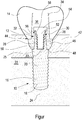
- the figure shows a schematic side view of a holding device with attached crown in a partially sectioned view.
- the holding device has an implant 10 and an intermediate element 12 which are connected to one another.
- a tooth replacement element 14 is placed, in particular glued.
- the implant 10 has an implant shaft 16. This in FIG. 1 non-cut part of the implant has a thread 20 on an outer side 18. This makes it possible to arrange the implant 10 in a jaw bone 22, in particular to screw.
- An implant head 25 with a projection 26 adjoins the implant shaft 16, which is rotationally symmetrical with respect to a longitudinal axis 24. This is preferably not rotationally symmetrical, but has, for example, a hexagonal or octagonal configuration, so that the projection 26 also serves as a tool attachment to screw the implant 10 into the jawbone 22.
- the intermediate element 12 has a recess 28. This is, in particular with respect to the longitudinal axis 24 arranged centrally in the intermediate element 12.
- the recess 28 is preferably formed congruent to the shape of the projection 26. This avoids a rotation or rotation of the intermediate element 12 on the implant introduced into the bone.
- a fixing member 30 is provided, which is a screw in the illustrated embodiment.
- the screw 30 is arranged in a through hole 32 of the intermediate element 12 and screwed into the projection 26 of the implant head 25.
- the projection 26 of the implant head 25 may have an opening or blind bore 33, which is open in the direction of the intermediate element 12.
- the intermediate element 12 has a projection 28 or projection 34 lying opposite the recess 28. This protrudes into a recess 36 of the tooth replacement element 14.
- the projection 34 and the recess 36 are in this case preferably again formed congruent.
- the implant 10 is anchored in the bone 22 by screwing in a first step. This is followed by sewing or Closing the gum 42 so that the implant 10 grows and is firmly connected to the bone 22. In the next step, the gum 42 is opened, since the implant 10 has an implant head 25, which is arranged above the jawbone 22 within the gum 42, the gum does not have to be opened to the bone.
- the intermediate element with a provisional crown outside mesiodistal and occlusal contact could already be screwed on after the implant placement and the gums around it sewn up. This has the advantage that in a later prosthetic restoration an already anatomically correctly shaped gingival socket is formed.
- the intermediate element 12 is subsequently fixed by means of the screw 30 in the projection 26 of the implant head 25.
- the intermediate element 12 has been previously processed in this way, in particular by grinding, and adapted to the individual tooth situation.
- the tooth replacement element 14 is placed by gluing on the intermediate element 12.
- the dental prosthetic item 14 is an anterior tooth crown or the like, it does not have an opening 36, as such an opening for the screw 30 can not be attached due to palatal angulation.
- the tooth replacement element 14 is placed on the intermediate element 12 by bonding by means of cement or other adhesive material in an anterior situation. Since the gap 44 between the intermediate member 12 and the dental prosthesis element 14 is located at anterior teeth only slightly below a top of the gum, excess cement material or the like can be easily removed, so that no irritation of the gums occur.
- the dental prosthesis element 14 has an opening 36. In this respect, it is possible, the tooth replacement element 14 outside the mouth by gluing with the help of cement or other adhesive material to bond with the intermediate element 12. The cement or adhesive material residues exiting in the region of the gap 44 can be removed before the intermediate element 12 connected to the dental prosthesis element 14 is fixed in the attachment 26 by means of the screw 30.
- the intermediate element 12 has a preferably circumferential collar 46. This has a preferably flat, flat bottom 48, which rests on a preferably flat and flat top 50 of the implant head. When fixing the intermediate element 12 by means of the screw 30, the underside 48 can be pressed against the support surface 50. This is in particular possible without play, since the material of the intermediate element 12 has a certain elasticity.
- the fixing element 30, which is designed in particular as a screw, has a shank 52 and a head 54. On an underside of the head 54, a recess 56 is provided.
- the recess 56 which is formed circumferentially, in this case has an inclined surface 58.
- the oblique surface 58 is provided a corresponding obliquely formed surface 60 opposite to the holding element 12.
Landscapes
- Health & Medical Sciences (AREA)
- Oral & Maxillofacial Surgery (AREA)
- Orthopedic Medicine & Surgery (AREA)
- Dentistry (AREA)
- Epidemiology (AREA)
- Life Sciences & Earth Sciences (AREA)
- Animal Behavior & Ethology (AREA)
- General Health & Medical Sciences (AREA)
- Public Health (AREA)
- Veterinary Medicine (AREA)
- Engineering & Computer Science (AREA)
- Ceramic Engineering (AREA)
- Dental Prosthetics (AREA)
Priority Applications (2)
| Application Number | Priority Date | Filing Date | Title |
|---|---|---|---|
| EP18154910.6A EP3520730A1 (fr) | 2018-02-02 | 2018-02-02 | Dispositif de maintien pour éléments de prothèse dentaire |
| PCT/EP2019/052284 WO2019149773A1 (fr) | 2018-02-02 | 2019-01-30 | Dispositif de retenue pour éléments de prothèse dentaire |
Applications Claiming Priority (1)
| Application Number | Priority Date | Filing Date | Title |
|---|---|---|---|
| EP18154910.6A EP3520730A1 (fr) | 2018-02-02 | 2018-02-02 | Dispositif de maintien pour éléments de prothèse dentaire |
Publications (1)
| Publication Number | Publication Date |
|---|---|
| EP3520730A1 true EP3520730A1 (fr) | 2019-08-07 |
Family
ID=61157098
Family Applications (1)
| Application Number | Title | Priority Date | Filing Date |
|---|---|---|---|
| EP18154910.6A Withdrawn EP3520730A1 (fr) | 2018-02-02 | 2018-02-02 | Dispositif de maintien pour éléments de prothèse dentaire |
Country Status (2)
| Country | Link |
|---|---|
| EP (1) | EP3520730A1 (fr) |
| WO (1) | WO2019149773A1 (fr) |
Cited By (2)
| Publication number | Priority date | Publication date | Assignee | Title |
|---|---|---|---|---|
| US20190321142A1 (en) * | 2018-04-19 | 2019-10-24 | Jong-pil Kim | Dental implant |
| DE102021120277A1 (de) | 2021-08-04 | 2023-02-09 | Fraunhofer-Gesellschaft zur Förderung der angewandten Forschung eingetragener Verein | Dentalimplantat-Mesostrukturen mit Formgedächtniseffekt |
Families Citing this family (1)
| Publication number | Priority date | Publication date | Assignee | Title |
|---|---|---|---|---|
| DE102021003024B4 (de) | 2021-06-12 | 2024-10-17 | Champions Dental International GmbH | Einteiliges Zahnimplantat |
Citations (6)
| Publication number | Priority date | Publication date | Assignee | Title |
|---|---|---|---|---|
| DE8905201U1 (de) * | 1989-04-25 | 1989-09-07 | Kanth, Lothar, 7800 Freiburg | Koronales intramobiles Element |
| US20060014120A1 (en) * | 2004-07-16 | 2006-01-19 | Sapian Schubert L | Biofunctional dental implant |
| WO2007074128A1 (fr) * | 2005-12-23 | 2007-07-05 | Sirona Dental Systems Gmbh | Prothese dentaire qui peut etre fixee a un implant au moyen d'une vis |
| DE102007018453B3 (de) * | 2007-04-17 | 2008-10-23 | Dental Service Center Michael Menzel Gmbh | Zahnimplantatsystem |
| US20150037759A1 (en) * | 2010-11-15 | 2015-02-05 | Holger Zipprich | Dental implant system and method for producing a dental implant system |
| US20160338802A1 (en) * | 2014-02-11 | 2016-11-24 | Heraeus Kulzer Gmbh | Dampening insert for dental implants |
Family Cites Families (3)
| Publication number | Priority date | Publication date | Assignee | Title |
|---|---|---|---|---|
| US5180303A (en) * | 1988-09-21 | 1993-01-19 | Regents Of The University Of California | Retrievable dental prothesis apparatus and method of fabrication |
| US5174755A (en) * | 1990-10-25 | 1992-12-29 | Olympus Optical Co., Ltd. | Dental implant |
| US8371851B2 (en) | 2004-03-12 | 2013-02-12 | Ivoclar Vivadent Ag | Dental implant abutment |
-
2018
- 2018-02-02 EP EP18154910.6A patent/EP3520730A1/fr not_active Withdrawn
-
2019
- 2019-01-30 WO PCT/EP2019/052284 patent/WO2019149773A1/fr not_active Ceased
Patent Citations (6)
| Publication number | Priority date | Publication date | Assignee | Title |
|---|---|---|---|---|
| DE8905201U1 (de) * | 1989-04-25 | 1989-09-07 | Kanth, Lothar, 7800 Freiburg | Koronales intramobiles Element |
| US20060014120A1 (en) * | 2004-07-16 | 2006-01-19 | Sapian Schubert L | Biofunctional dental implant |
| WO2007074128A1 (fr) * | 2005-12-23 | 2007-07-05 | Sirona Dental Systems Gmbh | Prothese dentaire qui peut etre fixee a un implant au moyen d'une vis |
| DE102007018453B3 (de) * | 2007-04-17 | 2008-10-23 | Dental Service Center Michael Menzel Gmbh | Zahnimplantatsystem |
| US20150037759A1 (en) * | 2010-11-15 | 2015-02-05 | Holger Zipprich | Dental implant system and method for producing a dental implant system |
| US20160338802A1 (en) * | 2014-02-11 | 2016-11-24 | Heraeus Kulzer Gmbh | Dampening insert for dental implants |
Cited By (4)
| Publication number | Priority date | Publication date | Assignee | Title |
|---|---|---|---|---|
| US20190321142A1 (en) * | 2018-04-19 | 2019-10-24 | Jong-pil Kim | Dental implant |
| DE102021120277A1 (de) | 2021-08-04 | 2023-02-09 | Fraunhofer-Gesellschaft zur Förderung der angewandten Forschung eingetragener Verein | Dentalimplantat-Mesostrukturen mit Formgedächtniseffekt |
| WO2023012058A1 (fr) | 2021-08-04 | 2023-02-09 | Fraunhofer-Gesellschaft zur Förderung der angewandten Forschung e.V. | Mésostructures d'implant dentaire à effet de mémoire de forme |
| DE102021120277B4 (de) | 2021-08-04 | 2024-10-17 | Fraunhofer-Gesellschaft zur Förderung der angewandten Forschung eingetragener Verein | Zahnersatzimplantat, enthaltend eine Mesostruktur mit Formgedächtniseffekt |
Also Published As
| Publication number | Publication date |
|---|---|
| WO2019149773A1 (fr) | 2019-08-08 |
Similar Documents
| Publication | Publication Date | Title |
|---|---|---|
| EP1855610B1 (fr) | Systeme d'implant dentaire comportant deux parties | |
| EP1993469B1 (fr) | Butée dentaire céramique/métallique et implant dentaire | |
| EP2170212B1 (fr) | Implant dentaire | |
| US10383710B2 (en) | Configurations for the connection of dental restorations with abutments | |
| WO2008155135A1 (fr) | Implant dentaire et procédé de mise à disposition d'une pièce de montage | |
| DE102005006979A1 (de) | Keramisches enossales Zahnimplantat | |
| EP2874563B1 (fr) | Système de pilier pour implants immédiats servant à remplacer une prothèse dentaire | |
| EP2170211A1 (fr) | Implant dentaire | |
| WO2019149773A1 (fr) | Dispositif de retenue pour éléments de prothèse dentaire | |
| EP2742905A1 (fr) | Implant dentaire | |
| KR100662583B1 (ko) | 크라운 임시고정용 임플란트 유니트 | |
| DE202008007189U1 (de) | Abutment für ein Schraubimplantat in einem Kieferknochen | |
| EP2800538B9 (fr) | Implant dentaire | |
| DE102006045186B4 (de) | Aufbau für ein zweiteiliges Zahnimplantat, sowie mehrteiliges Zahnimplantatssystem | |
| WO2005007012A2 (fr) | Implant dentaire | |
| LU507742B1 (de) | Abutmentsystem und kit mit einem solchen | |
| EP2845562A1 (fr) | Implant et système de prothèse dentaire | |
| Gutmann et al. | Implantatprothetische Komplikationen Von Prävention bis Management. | |
| DE202009000560U1 (de) | Multifunktionales Schraubimplantat | |
| DE3446223A1 (de) | Zahnaerztliches implantat | |
| DE202010002259U1 (de) | Einteiliges Zahnimplantat aus Zirkonoxidkeramik | |
| WO2010037376A2 (fr) | Système d'implant pour la fixation de dents artificielles | |
| EP1658824A2 (fr) | Support tronconique pour usage dans une élévation de la membrane du sinus pour la préparation de l'insertion d'un implant dentaire | |
| WO2014203225A1 (fr) | Implant dentaire pourvu d'un pilier court | |
| DE29911168U1 (de) | Suprakonstruktion zur Verankerung eines keramischen Aufbaus auf einem Dentalimplantat |
Legal Events
| Date | Code | Title | Description |
|---|---|---|---|
| PUAI | Public reference made under article 153(3) epc to a published international application that has entered the european phase |
Free format text: ORIGINAL CODE: 0009012 |
|
| STAA | Information on the status of an ep patent application or granted ep patent |
Free format text: STATUS: THE APPLICATION HAS BEEN PUBLISHED |
|
| AK | Designated contracting states |
Kind code of ref document: A1 Designated state(s): AL AT BE BG CH CY CZ DE DK EE ES FI FR GB GR HR HU IE IS IT LI LT LU LV MC MK MT NL NO PL PT RO RS SE SI SK SM TR |
|
| AX | Request for extension of the european patent |
Extension state: BA ME |
|
| STAA | Information on the status of an ep patent application or granted ep patent |
Free format text: STATUS: THE APPLICATION HAS BEEN WITHDRAWN |
|
| 18W | Application withdrawn |
Effective date: 20190805 |