EP2641471B1 - Verfahren und vorrichtung zur beschichtung eines raffbaren innenbeschichteten gewürzschlauchs - Google Patents
Verfahren und vorrichtung zur beschichtung eines raffbaren innenbeschichteten gewürzschlauchs Download PDFInfo
- Publication number
- EP2641471B1 EP2641471B1 EP13001328.7A EP13001328A EP2641471B1 EP 2641471 B1 EP2641471 B1 EP 2641471B1 EP 13001328 A EP13001328 A EP 13001328A EP 2641471 B1 EP2641471 B1 EP 2641471B1
- Authority
- EP
- European Patent Office
- Prior art keywords
- casing
- flavourings
- adhesive
- supply
- packaging
- Prior art date
- Legal status (The legal status is an assumption and is not a legal conclusion. Google has not performed a legal analysis and makes no representation as to the accuracy of the status listed.)
- Active
Links
Images


Classifications
-
- A—HUMAN NECESSITIES
- A22—BUTCHERING; MEAT TREATMENT; PROCESSING POULTRY OR FISH
- A22C—PROCESSING MEAT, POULTRY, OR FISH
- A22C13/00—Sausage casings
- A22C13/0003—Apparatus for making sausage casings, e.g. simultaneously with stuffing artificial casings
-
- A—HUMAN NECESSITIES
- A22—BUTCHERING; MEAT TREATMENT; PROCESSING POULTRY OR FISH
- A22C—PROCESSING MEAT, POULTRY, OR FISH
- A22C13/00—Sausage casings
- A22C13/0013—Chemical composition of synthetic sausage casings
-
- A—HUMAN NECESSITIES
- A22—BUTCHERING; MEAT TREATMENT; PROCESSING POULTRY OR FISH
- A22C—PROCESSING MEAT, POULTRY, OR FISH
- A22C13/00—Sausage casings
- A22C2013/002—Sausage casings made by extrusion
-
- A—HUMAN NECESSITIES
- A22—BUTCHERING; MEAT TREATMENT; PROCESSING POULTRY OR FISH
- A22C—PROCESSING MEAT, POULTRY, OR FISH
- A22C13/00—Sausage casings
- A22C2013/0046—Sausage casings suitable for impregnation with flavouring substances, e.g. caramel, liquid smoke, spices
-
- A—HUMAN NECESSITIES
- A22—BUTCHERING; MEAT TREATMENT; PROCESSING POULTRY OR FISH
- A22C—PROCESSING MEAT, POULTRY, OR FISH
- A22C13/00—Sausage casings
- A22C2013/0053—Sausage casings multilayer casings
-
- A—HUMAN NECESSITIES
- A22—BUTCHERING; MEAT TREATMENT; PROCESSING POULTRY OR FISH
- A22C—PROCESSING MEAT, POULTRY, OR FISH
- A22C13/00—Sausage casings
- A22C2013/0063—Sausage casings containing polyamide, e.g. nylon, aramide
-
- B—PERFORMING OPERATIONS; TRANSPORTING
- B05—SPRAYING OR ATOMISING IN GENERAL; APPLYING FLUENT MATERIALS TO SURFACES, IN GENERAL
- B05C—APPARATUS FOR APPLYING FLUENT MATERIALS TO SURFACES, IN GENERAL
- B05C7/00—Apparatus specially designed for applying liquid or other fluent material to the inside of hollow work
Definitions
- the invention relates to a method and a device for coating tubular food packaging casings, in particular intestines, with flavoring substances in particle form, in particular spices, in that the tubular packaging casing is wetted on the inside with adhesive and the desired flavoring substances are applied to the adhesive layer formed.
- Tubular sausage casings that are coated on the inside with spice particles are in the DE 195 00 470 has been proposed.
- This is based on a shirred sausage casing which, after being pulled off into the cylindrical shape, is initially wetted on the inside with a liquid adhesive.
- the sausage casing then slides along an inner coating ring, as a result of which the adhesive is to be distributed more evenly and is to be wiped off in the desired thickness.
- compressed air and spices are blown radially against the inner surface of the sausage casing via a central supply pipe, where it is held by the applied adhesive layer. Then the sausage casing must be dried.
- a rotating centrifugal disk can be provided at the end of the feed pipe, which throws the spice against the inside of the sausage casing with the additional influence of centrifugal force.
- tubular casings that are to be coated with spice in the form of flat films. Only then is the coated flat film then brought into the shape of a tube by making it into a cylindrical shape through matching shaping shoulders brought and then closed along their adjacent or overlapping longitudinal edges by sewing or gluing.
- the present invention is based on the object of providing a method for coating with aromatic substances that do not float in a carrier liquid but are in particle form, that is to say especially spices, herbs, powdered fruit flavors and the like.
- the starting material should not be a flat film, but a tubular packaging film, namely both natural casings and single or multi-layer fiber casings, single or multi-layer plastic casings and any other tubular textile casings.
- the packaging film according to the invention should be able to be gathered so that it can be stored, transported and, in particular, processed further in automatic filling and clipping machines without the fear of local flaking of the spices during the gathering.
- this object is achieved in that the inside of the packaging sleeve, which is wetted with adhesive, is brought into a non-flat, open cross-sectional shape by a particulate aroma supply introduced into the tube interior and a gas cushion, in particular an air cushion, so that the packaging sleeve is wetted with adhesive Inside takes aromas from the aroma supply when it is pulled through the aroma supply and that the packaging sleeve, at least on the inside, consists predominantly of a water-absorbing plastic.
- the invention is based on the one hand on the knowledge that the weight of the aroma particles filled into the packaging envelope, in conjunction with the air cushion above it, causes the aroma particles to accumulate intensively on the adhesive-coated inside of the packaging envelope.
- the invention is based on the knowledge that the previous wetting of the packaging sleeve with adhesive is surprisingly promoted by the fact that the packaging sleeve is made of a water-absorbing material on the inside - over the entire surface or locally.
- tubular packaging casings by pulling them through a filled aroma substance supply has been known for liquids for over 50 years. So it is through the U.S. 2,901,358 known to first pretreat a cellulose tube intended for sausage casings with glycerine so that it has an approximately gel-like consistency and then to fill the tube with a water-soluble chromium chloride solution and an air cushion between a lower and an upper pinch zone. If the hose is then pulled through the two aforementioned pinch zones, it is coated on the inside with the chromium chloride solution.
- the hose is inflated again by an air cushion and dried by hot air from 100 ° C to 110 ° C to a residual moisture of 4% to 6%, whereupon it is then brought into a flat shape and wound up on a roll.
- This inner coating ensures that the sausage casing can later be peeled off more easily from the filled sausage.
- Various materials can be used as water-absorbing plastics, including those with fibers, so that additional capillary effects result.
- Polyamides preferably PA 4, PA 6 or PA 6.6, which are distinguished by their comparatively high water absorption, are particularly suitable.
- a further improvement in adhesive absorption can be achieved by roughening the inside of the packaging sleeve.
- the desired surface roughness can be produced by physical or chemical processes, but preferably by UV radiation or by laser radiation or by corona treatment, in particular in combination with stretching the packaging sleeve.
- the aim is a roughness of at least 0.05 ⁇ m, in particular at least 0.1 ⁇ m.
- the plastic inner layer is preferably provided over the entire surface, that is to say over the entire inner circumference of the packaging casing.
- the plastic inner layer it is also within the scope of the invention to produce the plastic inner layer as a woven fabric, fleece or the like from fine plastic, in particular polyamide fibers, and possibly to achieve the desired roughness through this material mix.
- the packaging sleeve can consist entirely of the water-absorbing material.
- the polyamide that is preferably used is relatively expensive, it is advisable to design the packaging cover with multiple layers and to provide a thin layer of water-absorbing material only on the inside.
- the thickness of this material layer can be below 1/10 mm, preferably in the range between approximately 5 ⁇ m to approximately 50 ⁇ m, in particular between approximately 6 ⁇ m to approximately 20 ⁇ m.
- the inner layer made of water-absorbing material is expediently combined on the outside with cheaper materials, in particular polyethylene, so that the desired tear resistance is guaranteed.
- the combination with polyethylene also offers the great advantage that the packaging casing has a sufficient barrier effect against oxygen and water vapor.
- the multilayer structure of the packaging casing can be produced by coextrusion or by lamination.
- the packaging sleeve is expediently wetted with adhesive by introducing a liquid adhesive supply and possibly a gas cushion into the interior of the non-flat tubular sleeve and pulling the packaging sleeve through the adhesive supply. It is then recommended that the packaging casing pass at least one squeeze zone after it has been wetted with adhesive. This squeezing zone allows the amount of adhesive remaining on the packaging sleeve to be metered: the stronger the squeezing effect, the less adhesive the packaging sleeve is able to take through the squeezing zone.
- Such a squeezing zone can also be arranged below the aroma supply in order to form its lower end when the packaging casing is then pulled more or less steeply upwards through the aroma supply.
- the device for carrying out the described coating process has a first wetting station for wetting the inside of the packaging casing with adhesive and a second wetting station for wetting the inside of the packaging casing with aromatic substances, and that the packaging casing in both wetting stations is filled with glue or by filled in flavorings each in combination with a gas cushion has a non-flat, open cross-sectional shape.
- each wetting station is followed by at least one squeeze zone.
- the upstream connection of a squeeze zone in front of each wetting station is necessary if the packaging casing has an upward slope at the beginning of the wetting station.
- the packaging sleeve is guided in such a way that a sag occurs in which the packaging sleeve has at least partially a non-flat, open cross-section and with the adhesive used for the inside coating or flavoring is filled in combination with a gas cushion each. Then a squeeze zone is only recommended at the end of the wetting station.
- the crush zones can be created by funnel-like constrictions in the tubular packaging film - possibly combined with twisting.
- a particularly reliable seal in the upper squeeze zone is brought about by the fact that the packaging film is not only brought into a flat shape with a squeeze roller, but that two squeeze rollers are arranged parallel to one another, which have no or only a minimal gap for the packaging sleeve to pass through, see above that the reshaping of the inflated sack into the flat shape is combined with an additional compression of the two layers of tubes lying on top of one another. This results in a particularly effective embedding of the powdery flavoring substances in the adhesive layer of the packaging casing.
- the squeezing rollers preferably have a rubber-elastic outer jacket, for example made of foam rubber or the like.
- the contact pressure between the hose layers can be increased by the fact that the squeezing rollers have ribs running approximately in the axial direction on their outer surface, so to speak a slight external toothing, the ribs of adjacent rollers meshing with one another, i.e. engaging one another.
- a squeeze zone as the lower end of the aroma supply is dispensed with in that the packaging casing is brought into a sagging course in which it at least partially assumes the non-flat, open cross-sectional shape and with the aroma supply and a Gas cushion is filled.
- the same sagging principle can also be used when wetting with glue.
- the spices can have a smaller particle size than has been customary up to now.
- spices with a particle size corresponding to 8 mesh to 400 mesh, in particular corresponding to 30 mesh to 50 mesh are used.
- This smaller particle size leads to a stronger aromatization with the same amount of spice or allows the amount of spice to be reduced with the same amount of flavor, since the surface of the particles, which is decisive for the degree of flavoring, is increased in relation to their mass with a smaller particle size.
- the starting point is a supply roll 1 on which the tubular packaging casing 2 is wound in a flat form.
- the supply roll 1 can accommodate a 40 m to 500 m long packaging sleeve, for example.
- the packaging sleeve 2 has one or more layers and consists at least on the inside of polyamide, in particular a polyamide with high water absorption such as PA 6 or PA 6.6.
- the casing can consist of a wide variety of materials, for example it can be reinforced fiber casings, collagen casings or dried natural casings, but also coated textile casings or framework casings coated with collagen, carrageenan or acrylate or other - and multilayer Trade substances.
- Polyethylene is particularly suitable for combination with the polyamide inner layer.
- the packaging sleeve 2 which is an open end of the hose, a known liquid adhesive 3 and possibly also supporting air is filled in, so that the packaging sleeve is in the form of a sack 2a, which is partially or completely filled with adhesive 3 is.
- the amount of adhesive is measured in such a way that the entire packaging casing wound on the supply roll 1 can be coated with adhesive.
- the packaging sleeve 2 is supplied to the adhesive in dry form so that it is well absorbed.
- the absorption of the adhesive is facilitated by the fact that the inside of the packaging sleeve consists of polyamide, which is characterized by high water absorption. This guarantees intensive and even wetting of the packaging sleeve with the adhesive.
- a powdery or liquid preservative in particular based on potassium sorbate, can also be filled into the sack 2a, so that the packaging casing is protected from the formation of mold despite the high moisture content.
- this preservative can also be added later, for example together with the flavoring substances.
- the lower end of the sack 2a filled with adhesive is formed by its tight contact with the supply roll 1, which closes the sack.
- a pinch zone in the form of pinch rollers or the like could also be arranged here.
- the packaging sleeve then passes between two squeezing rollers 4a and 4b. These squeezing rollers press the packaging film into a flat shape and, through their squeezing force, define the amount of adhesive that can be taken along by the inside of the packaging sleeve when it passes through the two squeezing rollers.
- the packaging sleeve After passing through the first wetting station described above, the packaging sleeve arrives at a squeezing zone 5, which is formed by two squeezing rollers 5a and 5b, after which the packaging sleeve again assumes the shape of a sack that rises upwards and that is useful approximately vertically upwards and which is marked by the reference number 2b.
- This sack is filled in its lower area with dust-dry aroma particles 6, in particular spices corresponding to 30 mesh to 50 mesh, that is to say a grain size of approximately 0.3 mm to 0.6 mm.
- the squeezing zone 5 is designed with regard to its pressing against the walls of the packaging casing, which are held flat and lying against one another, in such a way that the aromatic substances 6 cannot slip downward out of the sack 2b.
- This air cushion 7 essentially has the task of separating the spices 6 from the upper end of the sack, which is formed by a further squeezing zone 8 in the form of two squeezing rollers 8a and 8b, so that only those Spice particles can pass the gap between the squeezing rollers 8a and 8b and adhere to the inner wall of the packaging casing 2, that is to say no lumps of spice from the supply 6 are picked up by the squeezing rollers and transported on.
- the packaging sleeve has then passed its second wetting station.
- the vibration of the sack 2b can be generated by externally acting vibrators or directly by corresponding vibrations of the upper squeezing rollers 8a and 8b.
- the squeezing rollers have a much larger diameter than conventional guide rollers. This, in conjunction with its rubber-elastic outer jacket, results in a strip several centimeters wide in the direction of advance of the packaging film, where the packaging sleeve is pressed together.
- the spices 6 as well as the air cushion 7 are introduced when a new packaging sleeve is threaded in, before the beginning of the packaging sleeve reaches the squeezing zone 8.
- the sack 2b is then sealed and at the same time the spice particles carried upwards by the packaging sleeve are pressed against the inner wall of the packaging sleeve by the crushing rollers 8a and 8b, so that they are firmly attached to the packaging sleeve during further processing stick and not fall off.
- the distance between the lower pinch zone 5 and the upper pinch zone 8 is expediently variable, in particular because the pinch rollers of the upper pinch zone 8 can be moved downwards in order to compensate for the decreasing volume of the bag 2b during the coating. This ensures that the packaging sleeve retains a firm sack shape, even if the sack itself becomes shorter and shorter as the coating increases, because the pinch zones 5 and 8 approach one another.
- the finished coated packaging sleeve arrives at a take-up roller 10, possibly via further guide rollers.
- the packaging sleeve As soon as the packaging sleeve has been threaded through all the squeezing rollers and filled with adhesive 3, spices 6 and air cushion 7, and attached to the take-up roll 9, it runs continuously from the supply roll 1 to the take-up roll 9 and is coated in the process.
- the packaging sleeve is expediently advanced by the squeezing rollers themselves. In general, it is sufficient if only one of two corresponding squeezing rollers is driven, in the exemplary embodiment this is the squeezing roller with the blackened arrow indicating the direction of rotation.
- One of the two squeezing rollers is preferably adjustable in terms of its distance from the adjacent squeezing roller in all squeezing zones in order to facilitate the threading of the packaging sleeve 2.
- the described packaging sleeve 2 apart from its water-absorbing inner layer, can consist of almost any material, be single or multi-layered, possibly also with coatings and / or laminates, in particular to make the sleeve largely impermeable to water vapor and / or oxygen.
- the coated packaging casing 2 is fed to a take-up roll 10 in flat form. Instead, it is also possible to gather the packaging sleeve online.
- the finished coated packaging casing 2 is conveyed axially onto a cylindrical shirring tube 11, specifically by means of several shirring rollers distributed over the circumference, of which two shirring rollers 12a and 12b are visible. After passing these gathering rollers, about 5 m to about 50 m long sections of the packaging casing are formed into accordion-like beads 13 by axial compression, as are preferred by the meat and cheese industry.
- the gathering process itself is known per se and is therefore not described in further detail. It is essential, however, that the gathering process directly follows the inner coating of the packaging casing with spice particles, without the packaging casing requiring heating or drying. This results in considerable energy savings.
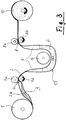
- Figure 3 shows a guide according to the invention for the packaging sleeve 2.
- the lower squeeze zone 5 and the formation of the vertical sack 2b are dispensed with and the packaging sleeve is instead guided so that it forms a slack 15.
- the packaging sleeve is in the area of this slack the particulate aroma supply 6 partially filled so that the aroma supply collects in the lower area of the slack, whereas air cushions 7 are contained in the packaging envelope in the two upward areas of the slack 15 above the aroma supply.
- the aroma substance store 6 is dimensioned in such a way that it wets the packaging casing along its entire circumference until the end of the coating process.
- the aroma substance supply 6 is higher in the part of the slack 15 that rises to the right than in the left-hand area. This is due to the fact that the packaging casing, due to its advance, transports aroma into the branch of the sagging 15 rising to the right until a state of equilibrium is established due to the difference in filling height.
- the slack 15 runs around a roller 16 arranged within the passage Maintains the desired sag depth during the coating process. It is essentially a matter of keeping the aroma substance supply 6 sufficiently distanced from the following squeezing zone 8.
Landscapes
- Life Sciences & Earth Sciences (AREA)
- Engineering & Computer Science (AREA)
- Wood Science & Technology (AREA)
- Zoology (AREA)
- Food Science & Technology (AREA)
- Formation And Processing Of Food Products (AREA)
- Packging For Living Organisms, Food Or Medicinal Products That Are Sensitive To Environmental Conditiond (AREA)
- Packages (AREA)
- General Preparation And Processing Of Foods (AREA)
- Application Of Or Painting With Fluid Materials (AREA)
- Processing Of Meat And Fish (AREA)
Description
- Die Erfindung betrifft ein Verfahren und eine Vorrichtung zur Beschichtung schlauchförmiger Lebensmittel-Verpackungshüllen, insbesondere Därme, mit Aromastoffen in Partikelform, insbesondere Gewürzen, indem die schlauchförmige Verpackungshülle innenseitig mit Kleber benetzt wird und auf die gebildete Kleberschicht die gewünschten Aromastoffe aufgebracht werden.
- Schlauchförmige Wursthüllen, die innenseitig mit Gewürzpartikeln beschichtet werden, sind in der
DE 195 00 470 vorgeschlagen worden. Dabei wird von einer gerafften Wursthülle ausgegangen, die nach dem Abziehen in die zylindrische Form zunächst innenseitig mit einem flüssigen Kleber benetzt wird. Sodann gleitet die Wursthülle an einem inneren Beschichtungsring entlang, wodurch der Kleber gleichmäßiger verteilt und in der gewünschten Dicke abgestrichen werden soll. Im weiteren Verlauf wird über ein zentrales Zuführrohr Druckluft und Gewürz radial gegen die Innenfläche der Wursthülle geblasen, wo es von der aufgetragenen Kleberschicht gehalten wird. Anschließend muss die Wursthülle getrocknet werden. - Um die Haftung der Gewürze zu verbessern, kann am Ende des Zuführrohres eine rotierende Schleuderscheibe vorgesehen sein, die das Gewürz unter zusätzlichem Fliehkrafteinfluss gegen die Innenseite der Wursthülle schleudert.
- In der Praxis hat sich dieses System jedoch nicht bewährt, weil keine gleichmäßige und genügend starke Beschichtung mit Aromastoffen auf Dauer gewährleistet war.
- Stattdessen ist es immer noch üblich, schlauchförmige Hüllen, die mit Gewürz beschichtet werden sollen, zuerst in Form von Flachfolien herzustellen und zu beschichten. Erst anschließend wird die beschichtete Flachfolie dann in Schlauchform gebracht, indem sie durch passende Formschultern in Zylinderform gebracht und dann entlang ihrer benachbarten oder sich überlappender Längsränder durch Nähen oder Kleben verschlossen wird.
- Dieser Prozess ist zeit- und energieaufwendig, denn der Kleber muss in feuchtem, flüssigem Zustand auf die Folie aufgebracht werden mit der Folge, dass die Folie nach dem Aufbringen der Aromastoffe einer intensiven Trocknung unterzogen werden muss. Erst nach dem Trocknen kann die mit Kleber und Gewürz beschichtete Flachfolie dann in Schlauchform gebracht und durch Nähen, Kleben oder Schweißen verschlossen und konfektioniert werden.
- Hingegen wären diese Verarbeitungsschritte im Feuchtezustand der Folie sowohl aus hygienischen wie auch aus arbeitstechnischen Gründen unmöglich.
- Durch die
DE 103 14 699 A1 ist es zum einen bekannt, körnige oder stückige Nahrungsmittelzusatzstoffe auf eine in flacher Bahnform vorliegende Lebensmittel-Verpackungshülle aufzustreuen. Dabei wird zuvor eine Bindemittelschicht auf die Hülle aufgetragen oder die körnigen Nahrungsmittelzusatzstoffe werden vor dem Auftrag mit einem Bindemittel kombiniert. Diese Flachbahn wird dann zu einem Schlauch geformt und mit einer Naht fixiert. Zum anderen ist es aus dieser Schrift bekannt, schlauchförmige Hüllen auf der Innenseite mit Farb- und/oder Aromastoffen zu tränken bzw. zu benetzen mit Hilfe einer Flüssigkeitsblase, die durch das Innere der Hülle hindurchgeführt wird. Als Material für die Hülle wird eine saugfähige Textilhülle offenbart, die aus Kunststofffasern bestehen kann. - Des Weiteren schlägt die nicht vorveröffentlichte
EP 2 436 268 A1 bereits vor, schlauchförmige Lebensmittel-Verpackungshüllen innenseitig mit Kleber zu benetzen, die Hülle danach durch eine Quetschzone und eine in Vorschubrichtung folgende weitere Quetschzone zu führen, wobei die schlauchförmige Verpackungshülle im Bereich zwischen den genannten Quetschzonen durch einen in das Schlauchinnere eingebrachten partikelförmigen Aromastoff-Vorrat und ein Luftpolster in die Form eines aufgeblasenen Sackes gebracht wird. - Von diesem Stand der Technik ausgehend, liegt der vorliegenden Erfindung die Aufgabe zugrunde, ein Verfahren zur Beschichtung mit Aromastoffen, die nicht in einer Trägerflüssigkeit schwimmen, sondern in Partikelform vorliegen, also insbesondere Gewürzen, Kräuter, pulverisierten Fruchtaromen und dergleichen, zu entwickeln. Dabei soll als Ausgangsmaterial keine Flachfolie, sondern direkt schlauchförmige Verpackungsfolie verwendet werden, und zwar sowohl Naturdärme wie auch ein- oder mehrlagige Faserdärme, ein- oder mehrlagige Kunststoffdärme und beliebige sonstige schlauchförmige Textilhüllen. Des Weiteren soll die erfindungsgemäße Verpackungsfolie raffbar sein, damit sie gut gelagert, transportiert und insbesondere bei automatischen Füll- und Klippmaschinen weiterverarbeitet werden kann, ohne dass beim Raffen ein lokales Abplatzen der Gewürze zu befürchten ist.
- Diese Aufgabe wird erfindungsgemäß dadurch gelöst, dass die innenseitig mit Kleber benetzte Verpackungshülle durch einen in das Schlauchinnere eingebrachten partikelförmigen Aromastoff-Vorrat und ein Gaspolster, insbesondere Luftpolster, in eine nicht-flache, offene Querschnittsform gebracht wird, dass die Verpackungshülle an ihrer mit Kleber benetzten Innenseite Aromastoffe aus dem Aromastoff-Vorrat mitnimmt, wenn sie durch den Aromastoff-Vorrat hindurchgezogen wird und dass die Verpackungshülle zumindest innenseitig überwiegend aus einem wasseraufnehmenden Kunststoff besteht.
- Die Erfindung beruht zum einen auf der Erkenntnis, dass das Gewicht der in die Verpackungshülle eingefüllten Aromapartikel in Verbindung mit dem darüber befindlichen Luftpolster eine intensive Anlagerung der Aromapartikel an der mit Kleber beschichteten Innenseite der Verpackungshülle bewirkt. Zum anderen beruht die Erfindung auf der Erkenntnis, dass die vorherige Benetzung der Verpackungshülle mit Kleber überraschend dadurch begünstigt wird, dass die Verpackungshülle innenseitig - ganzflächig oder lokal - aus einem wasseraufnehmenden Material besteht.
- Die Innenbeschichtung schlauchförmiger Verpackungshüllen, indem sie durch einen eingefüllten Aromastoff-Vorrat hindurchgezogen werden, ist zwar schon seit über 50 Jahren für Flüssigkeiten bekannt. So ist es durch die
US 2,901,358 bekannt, einen für Wursthüllen bestimmten Celluloseschlauch zunächst mit Glycerin vorzubehandeln, so dass er eine etwa gelartige Konsistenz erhält und den Schlauch dann zwischen einer unteren und einer oberen Quetschzone mit einer wasserlöslichen Chromchlorid-Lösung sowie einem Luftpolster zu füllen. Wird der Schlauch dann durch die beiden genannten Quetschzonen hindurchgezogen, erhält er an seiner Innenseite eine Beschichtung mit der ChromchloridLösung. Hinter der zweiten Quetschzone wird der Schlauch wieder durch ein Luftpolster in aufgeblasene Form gebracht und durch Heißluft von 100°C bis 110°C auf eine Restfeuchtigkeit von 4 % bis 6 % getrocknet, worauf er dann in Flachform gebracht und auf einer Rolle aufgewickelt wird. Diese Innenbeschichtung dient dazu, dass die Wursthülle später von der eingefüllten Wurst leichter abgeschält werden kann. Es lag aber nicht nahe, dieses Prinzip so abzuwandeln, dass eine Beschichtung mit partikelförmigen Aromastoffen ermöglicht wird, die nicht in einer Trägerflüssigkeit schwimmen, sondern in trockener Form vorliegen. - Erst recht lag es nicht nahe, dass die innenseitige Benetzung der Verpackungshülle mit Kleber dadurch begünstigt wird, indem die Verpackungshülle innenseitig zumindest überwiegend aus wasseraufnehmendem Kunststoff besteht. Dadurch ergibt sich überraschend eine intensivere, gleichmäßigere und schnellere Benetzung der Verpackungshülle durch den Kleber. Sie kann dadurch mit höherer Vorschubgeschwindigkeit durch die Beschichtungsanlage hindurchgezogen werden, bei gleichzeitiger Verbesserung der Beschichtungsqualität.
- Als wasseraufnehmende Kunststoffe kommen unterschiedliche Werkstoffe in Betracht, auch solche mit Fasern, so dass sich zusätzliche Kapillar-Effekte ergeben. Besonders geeignet sind Polyamide, vorzugsweise PA 4, PA 6 oder PA 6.6, die sich durch vergleichsweise hohe Wasseraufnahme auszeichnen.
- Eine weitere Verbesserung der Klebstoff-Aufnahme lässt sich dadurch erzielen, dass die Verpackungshülle innenseitig aufgerauht ist. Die gewünschte Oberflächenrauigkeit kann durch physikalische oder chemische Verfahren erzeugt werden, vorzugsweise aber durch UV-Bestrahlung oder durch Laserstrahlung oder durch Corona-Behandlung, insbesondere in Kombination mit einem Strecken der Verpackungshülle. Angestrebt wird eine Rauhigkeit von zumindest 0,05 µm, insbesondere zumindest 0,1 µm.
- Vorzugsweise wird die Kunststoff-Innenlage vollflächig, also über den gesamten inneren Umfang der Verpackungshülle vorgesehen. Es liegt aber auch im Rahmen der Erfindung, die Kunststoff-Innenlage als Gewebe, Vlies oder dergleichen aus feinen Kunststoff-, insbesondere Polyamid-Fasern herzustellen und eventuell bereits durch diesen Materialmix die gewünschte Rauhigkeit zu erzielen.
- Grundsätzlich kann die Verpackungshülle vollständig aus dem wasseraufnehmenden Material bestehen. Da aber das bevorzugt eingesetzte Polyamid relativ teuer ist, empfiehlt es sich, die Verpackungshülle mehrlagig auszubilden und nur innenseitig eine dünne Lage aus wasseraufnehmendem Material vorzusehen. Die Dicke dieser Material-Lage kann unterhalb 1/10 mm liegen, vorzugsweise im Bereich zwischen etwa 5 µm bis etwa 50 µm, insbesondere zwischen etwa 6 µm bis etwa 20 µm.
- Die Innenlage aus wasseraufnehmendem Material wird außen zweckmäßig mit kostengünstigeren Werkstoffen, insbesondere Polyethylen kombiniert, damit die gewünschte Reißfestigkeit gewährleistet ist.
- Die Kombination mit Polyethylen bietet außerdem den großen Vorteil, dass die Verpackungshülle eine ausreichende Sperrwirkung gegenüber Sauerstoff und Wasserdampf erhält.
- Der mehrlagige Aufbau der Verpackungshülle kann durch Coextrusion oder durch Laminieren hergestellt werden.
- Zweckmäßig erfolgt die Benetzung der Verpackungshülle mit Kleber, indem ein flüssiger Kleber-Vorrat und ggf. ein Gaspolster in das Innere der in nicht flacher Form vorliegenden Schlauchhülle eingebracht werden und die Verpackungshülle durch den Kleber-Vorrat hindurchgezogen wird. Es empfiehlt sich dann, dass die Verpackungshülle nach ihrer Benetzung mit Kleber zumindest eine Quetschzone passiert. Diese Quetschzone erlaubt es, die an der Verpackungshülle verbleibende Klebermenge zu dosieren: Je stärker die Quetschwirkung ist, desto weniger Kleber vermag die Verpackungshülle durch die Quetschzone hindurch mitzunehmen.
- Eine derartige Quetschzone kann auch unterhalb des Aromastoff-Vorrates angeordnet sein, um dessen unteren Abschluss zu bilden, wenn die Verpackungshülle anschließend mehr oder weniger steil nach oben durch den Aromastoff-Vorrat hindurchgezogen wird.
- Somit kann im Ergebnis festgestellt werden, dass die Vorrichtung zur Durchführung des beschriebenen Beschichtungsverfahrens eine erste Benetzungsstation zur innenseitigen Benetzung der Verpackungshülle mit Kleber und eine zweite Benetzungsstation zur innenseitigen Benetzung der Verpackungshülle mit Aromastoffen aufweist und dass die Verpackungshülle in beiden Benetzungsstationen durch eingefüllten Kleber bzw. durch eingefüllte Aromastoffe jeweils in Kombination mit einem Gaspolster eine nicht-flache, offene Querschnitssform aufweist.
- Des Weiteren ist jeder Benetzungsstation zumindest eine Quetschzone nachgeschaltet.
- Die Vorschaltung einer Quetschzone vor jeder Benetzungsstation ist dann erforderlich, wenn die Verpackungshülle am Beginn der Benetzungsstation einen ansteigenden Verlauf aufweist. Stattdessen wird erfindungsgemäß die Verpackungshülle so geführt dass ein Durchhang entsteht, in welchem die Verpackungshülle zumindest teilweise einen nicht-flachen, offenen Querschnitt aufweist und mit dem zur innenseitigen Beschichtung dienenden Kleber oder Aromastoff in Kombination mit jeweils einem Gaspolster gefüllt ist. Dann empfiehlt sich nur am Ende der Benetzungsstation eine Quetschzone.
- Für die Ausbildung der Quetschzonen bieten sich dem Fachmann verschiedene Möglichkeiten. So können die Quetschzonen etwa durch trichterartige Einschnürungen der schlauchförmigen Verpackungsfolie - eventuell kombiniert mit einer Tordierung - erzeugt werden. Besonders günstig ist es aber, die Quetschzonen durch Quetschrollen zu erzeugen, wo die schlauchförmige Verpackungsfolie in eine flache Form gezwungen wird, wo also die Wände der schlauchförmigen Verpackungsfolie in dichte Anlage miteinander gebracht werden. Eine besonders zuverlässige Abdichtung in der oberen Quetschzone wird dadurch herbeigeführt, dass die Verpackungsfolie nicht nur mit einer Quetschrolle in eine flache Form gebracht wird, sondern dass zwei Quetschrollen parallel nebeneinander angeordnet werden, die keinen oder nur einen minimalen Spalt zum Durchlass der Verpackungshülle aufweisen, so dass die Umformung des aufgeblasenen Sackes in die Flachform mit einer zusätzlichen Kompression der beiden aufeinander liegenden Schlauchlagen kombiniert wird. Man erhält dadurch eine besonders wirksame Einbettung der pulverförmigen Aromastoffe in die Kleberschicht der Verpackungshülle.
- Damit das Zusammenpressen ohne lokale Beschädigung der relativ dünnen Verpackungshülle gewährleistet ist, haben die Quetschrollen vorzugsweise einen gummielastischen Außenmantel, etwa aus Moosgummi oder dergleichen. Außerdem lässt sich die Anpresswirkung zwischen den Schlauchlagen noch dadurch erhöhen, dass die Quetschrollen an ihrem Außenmantel etwa in Axialrichtung laufende Rippen, also gewissermaßen eine leichte Außenverzahnung aufweisen, wobei die Rippen benachbarter Rollen miteinander kämmen, also ineinander greifen.
- Im Rahmen der Erfindung wird auf eine Quetschzone als unteren Abschluss des Aromastoff-Vorrates verzichtet, indem die Verpackungshülle in einen nach unten durchhängenden Verlauf gebracht wird, in welchem sie zumindest teilweise die nicht-flache, offene Querschnittsform einnimmt und mit dem Aromastoff-Vorrat und einem Gaspolster gefüllt ist. Das gleiche Durchhang-Prinzip lässt sich auch bei der Benetzung mit Kleber anwenden.
- Bei Versuchen mit dem erfindungsgemäßen Verfahren hat sich überraschend gezeigt, dass die Gewürze eine kleinere Partikelgröße als bisher üblich aufweisen können. Vorzugsweise werden deshalb Gewürze einer Partikelgröße entsprechend 8 Mesh bis 400 Mesh, insbesondere entsprechend 30 Mesh bis 50 Mesh verwendet. Diese kleinere Partikelgröße führt bei gleicher Gewürzmenge zu einer stärkeren Aromatisierung oder erlaubt bei gleichbleibender Aromatisierung die Verringerung der Gewürzmenge, da die für den Aromatisierungsgrad entscheidende Oberfläche der Partikel bezogen auf ihre Masse bei kleinerer Partikelgröße erhöht wird.
- Weitere Merkmale und Vorteile der Erfindung ergeben sich aus den Unteransprüchen und der nachfolgenden Beschreibung eines Ausführungsbeispieles sowie aus der Zeichnung; dabei zeigt
- Fig. 1
- eine schematische Darstellung des kompletten Beschichtungsverfahrens, wobei die fertig beschichtete Verpackungshülle am Ende aufgerollt wird;
- Fig. 2
- die gleiche Darstellung, wobei die Verpackungshülle am Ende gerafft wird;
- Fig. 3
- eine Alternative, bei welcher die Verpackungshülle einen Durchhang bildet.
- Ausgegangen wird von einer Vorratsrolle 1, auf welcher die schlauchförmige Verpackungshülle 2 in flacher Form aufgewickelt ist. Die Vorratsrolle 1 kann beispielsweise eine 40 m bis 500 m lange Verpackungshülle aufnehmen.
- Die Verpackungshülle 2 ist ein- oder mehrlagig und besteht zumindest innenseitig aus Polyamid, insbesondere einem Polyamid mit hoher Wasseraufnahme wie PA 6 oder PA 6.6. Abgesehen von der wasseraufnehmenden Innenlage kann die Hülle aus unterschiedlichstem Material bestehen, beispielsweise kann es sich um ggf. verstärkte Faserdärme, um Collagendärme oder getrocknete Naturdärme, aber auch um beschichtete Textildärme oder um Gerüstdärme, die mit Collagen, Carrageen oder Acrylat beschichtet sind oder sonstige ein- und mehrlagige Stoffe handeln. Besonders geeignet zur Kombination mit der Polyamid-Innenlage ist Polyethylen.
- In den Beginn der Verpackungshülle 2, der sich als offenes Schlauchende darstellt, wird ein an sich bekannter, lebensmittelrechtlich zugelassener flüssiger Klebstoff 3 und eventuell auch Stützluft eingefüllt, so dass die Verpackungshülle die Form eines Sackes 2a erhält, der teilweise oder vollständig mit Klebstoff 3 gefüllt ist. Die Klebstoffmenge wird so bemessen, dass die gesamte auf der Vorratsrolle 1 aufgewickelte Verpackungshülle mit Klebstoff beschichtet werden kann. Die Verpackungshülle 2 wird in trockener Form dem Klebstoff zugeführt, so dass er gut aufgenommen wird. Begünstigt wird die Aufnahme des Klebstoffes dadurch, dass die Verpackungshülle innen aus Polyamid besteht, das sich durch hohe Wasseraufnahme auszeichnet. Dies garantiert eine intensive und gleichmäßige Benetzung der Verpackungshülle mit dem Kleber.
- Gleichzeitig kann in den Sack 2a auch ein pulverförmiges oder flüssiges Konservierungsmittel, insbesondere auf Basis von Kaliumsorbat eingefüllt werden, damit die Verpackungshülle trotz hohen Feuchtigkeitsgehaltes vor Schimmelbildung geschützt ist. Alternativ oder zusätzlich kann dieses Konservierungsmittel auch später, etwa zusammen mit den Aromastoffen, zugeführt werden.
- Als Kleber eignen sich alle lebensmittelrechtlich zugelassenen Stoffe, insbesondere Stärke, modifizierte Stärke, Gelatine, Pullulan, Xanthangum, Casein, Collagen, Carrageen, Alginat, Carboxymethylcellulose und dergleichen, jeweils in niedrig-viskoser Lösung, um eine gute Benetzung sicherzustellen.
- Das untere Ende des mit Klebstoff gefüllten Sackes 2a wird im Ausführungsbeispiel durch seine dichte, den Sack verschließende Anlage an der Vorratsrolle 1 gebildet. Stattdessen könnte hier auch eine Quetschzone in Form von Quetschrollen oder dergleichen angeordnet sein.
- Anschließend gelangt die Verpackungshülle zwischen zwei Quetschrollen 4a und 4b. Diese Quetschrollen drücken die Verpackungsfolie in eine flache Form und definieren durch ihre Quetschkraft die Klebstoffmenge, die beim Passieren der beiden Quetschrollen von der Verpackungshülle an ihrer Innenseite mitgenommen werden kann.
- Nach dem Passieren der oben beschriebenen ersten Benetzungsstation gelangt die Verpackungshülle zu einer Quetschzone 5, die durch zwei Quetschrollen 5a und 5b gebildet ist, nach deren Passieren die Verpackungshülle wieder die Form eines Sackes annimmt, der nach oben ansteigt und zwar zweckmäßig etwa senkrecht nach oben und der durch das Bezugszeichen 2b markiert ist. Dieser Sack ist in seinem unteren Bereich mit staubtrockenen Aromapartikeln 6, insbesondere Gewürzen entsprechend 30 Mesh bis 50 Mesh, also einer Korngröße von etwa 0,3 mm bis 0,6 mm gefüllt. Die Quetschzone 5 ist hinsichtlich ihrer Anpressung gegen die flach gehaltenen und aneinander liegenden Wände der Verpackungshülle so ausgebildet, dass die Aromastoffe 6 nicht nach unten aus dem Sack 2b herausrutschen können.
- Im oberen Bereich des Sackes befindet sich ein Luftpolster 7. Dieses Luftpolster 7 hat im Wesentlichen die Aufgabe, die Gewürze 6 vom oberen Sackende, das durch eine weitere Quetschzone 8 in Form zweier Quetschrollen 8a und 8b gebildet wird, zu distanzieren, so dass nur diejenigen Gewürzpartikel den Spalt zwischen den Quetschrollen 8a und 8b passieren können, die an der Innenwand der Verpackungshülle 2 haften, also keine Gewürzklumpen aus dem Vorrat 6 von den Quetschrollen erfasst und weiterbefördert werden. Die Verpackungshülle hat dann ihre zweite Benetzungsstation passiert.
- Dabei ist es besonders zweckmäßig, den Sack 2b, insbesondere im oberen Bereich, leichten Vibrationen zu unterziehen, so dass zusammengebackene Gewürzklumpen von der Verpackungshülle 2 abgeschüttelt werden und in den Vorrat 6 zurückfallen. Die Gleichmäßigkeit der Gewürzbeschichtung wird dadurch sehr verbessert. Die Vibration des Sackes 2b kann durch extern angreifende Schwinger oder direkt durch entsprechende Schwingungen der oberen Quetschrollen 8a und 8b erzeugt werden.
- Die Quetschrollen haben wesentlich größere Durchmesser als übliche Führungsrollen. Dies in Verbindung mit ihrem gummielastischen Außenmantel führt dazu, dass ein in Vorschubrichtung der Verpackungsfolie mehrere Zentimeter breiter Streifen entsteht, wo die Verpackungshülle zusammengepresst wird.
- Das Einbringen der Gewürze 6 wie auch des Luftpolsters 7 erfolgt beim Einfädeln einer neuen Verpackungshülle, bevor der Beginn der Verpackungshülle die Quetschzone 8 erreicht. Nach Passieren der Quetschrollen 8a und 8b ergibt sich dann eine Abdichtung des Sackes 2b und gleichzeitig werden die von der Verpackungshülle nach oben mitgenommenen Gewürzteilchen durch die Quetschrollen 8a und 8b gegen die Innenwand der Verpackungshülle gepresst, so dass sie bei der weiteren Verarbeitung der Verpackungshülle gut daran haften und nicht abfallen.
- Der Abstand zwischen der unteren Quetschzone 5 und der oberen Quetschzone 8 ist zweckmäßigerweise veränderlich, insbesondere dadurch, dass die Quetschrollen der oberen Quetschzone 8 nach unten verfahren werden können, um das während der Beschichtung abnehmende Volumen des Sackes 2b zu kompensieren. Dadurch ist sichergestellt, dass die Verpackungshülle eine pralle Sackform beibehält, auch wenn der Sack selbst mit zunehmender Beschichtung immer kürzer wird, weil sich die Quetschzonen 5 und 8 annähern.
- Direkt hinter der Quetschzone 8 folgt zweckmäßig eine weitere Quetschzone 9, die durch Quetschrollen 9a und 9b gebildet ist. Sie intensiviert den Verbund zwischen der Verpackungshülle und den mitgenommenen Gewürzen und verbessert die Abdichtung gegenüber dem Luftpolster 7.
- Schließlich gelangt die fertig beschichtete Verpackungshülle - ggf. über weitere Führungsrollen - zu einer Aufwickelrolle 10.
- Sobald die Verpackungshülle durch sämtliche Quetschrollen durchgefädelt und dabei mit Klebstoff 3, Gewürzen 6 und Luftpolster 7 gefüllt, und an der Aufwickelrolle 9 befestigt worden ist, läuft sie kontinuierlich von der Vorratsrolle 1 zur Aufwickelrolle 9 und wird dabei beschichtet. Der Vorschub der Verpackungshülle erfolgt zweckmäßig durch die Quetschrollen selbst. Im Allgemeinen genügt es dabei, wenn immer nur eine von zwei miteinander korrespondierenden Quetschrollen angetrieben wird, im Ausführungsbeispiel ist dies jeweils die Quetschrolle mit dem geschwärzten Drehrichtungspfeil.
- Eine Zwischentrocknung der Verpackungshülle erübrigt sich, denn durch entsprechende Prozessführung wird ihre Feuchtigkeit nach der Gewürzbeschichtung bei etwa 10 % bis maximal etwa 20 % gehalten.
- Vorzugsweise ist in allen Quetschzonen eine der beiden Quetschrollen hinsichtlich ihres Abstandes zur benachbarten Quetschrolle verstellbar, um das Einfädeln der Verpackungshülle 2 zu erleichtern.
- Die beschriebene Verpackungshülle 2 kann abgesehen von ihrer wasseraufnehmenden Innenlage aus nahezu beliebigem Material bestehen, ein oder mehrlagig ausgebildet sein, ggf. auch mit Beschichtungen und/oder mit Laminaten, insbesondere um die Hülle gegenüber Wasserdampf und/oder Sauerstoff weitgehend undurchlässig zu machen.
- Im Ausführungsbeispiel wird die beschichtete Verpackungshülle 2 in flacher Form einer Aufwickelrolle 10 zugeführt. Stattdessen ist es aber auch möglich, die Verpackungshülle online zu raffen.
- Diese besonders bevorzugte Variante ist in
Figur 2 dargestellt. Die fertig beschichtete Verpackungshülle 2 wird dazu axial auf ein zylindrisches Raffrohr 11 gefördert, und zwar mittels mehrerer über den Umfang verteilter Raffrollen, von denen zwei Raffrollen 12a und 12b sichtbar sind. Nach Passieren dieser Raffrollen werden etwa 5 m bis etwa 50 m lange Abschnitte der Verpackungshülle, durch axiale Stauchung in Ziehharmonika-artige Raupen 13 geformt, wie sie bevorzugt von der Fleischwaren- und Käseindustrie gewünscht werden. - Der Raffvorgang selbst ist an sich bekannt und wird deshalb nicht weiter im Detail beschrieben. Wesentlich ist aber, dass sich der Raffvorgang direkt an die Innenbeschichtung der Verpackungshülle mit Gewürzpartikeln anschließt, ohne dass die Verpackungshülle einer Erhitzung bzw. Trocknung bedarf. Dadurch ergibt sich eine erhebliche Energieeinsparung.
-
Figur 3 zeigt eine erfindungsgemäße Führung der Verpackungshülle 2. Dabei wird auf die untere Quetschzone 5 und auf die Bildung des vertikalen Sackes 2b verzichtet und die Verpackungshülle wird stattdessen so geführt, dass sie einen Durchhang 15 bildet. Im Bereich dieses Durchhanges ist die Verpackungshülle mit dem partikelförmigen Aromastoff-Vorrat 6 teilweise gefüllt, so dass sich der Aromastoff-Vorrat im unteren Bereich des Durchhanges sammelt, wogegen in den beiden nach oben laufenden Bereichen des Durchhanges 15 oberhalb des Aromastoff-Vorrates Luftpolster 7 in der Verpackungshülle enthalten sind. Wesentlich dabei ist, dass der Aromastoff-Vorrat 6 so bemessen ist, dass er bis zum Schluss des Beschichtungsverfahrens die Verpackungshülle entlang deren gesamten Umfang benetzt. - Wie
Figur 3 zeigt, steht der Aromastoff-Vorrat 6 in dem rechts ansteigenden Teil des Durchhanges 15 höher als im linken Bereich. Dies rührt daher, dass die Verpackungshülle aufgrund ihres Vorschubes, Aromastoff in den rechts ansteigenden Ast des Durchhanges 15 transportiert, bis sich aufgrund der Füllhöhen-Differenz ein Gleichgewichtszustand einstellt. - Im Ausführungsbeispiel verläuft der Durchhang 15 um eine innerhalb des Durchganges angeordnete Rolle 16. Zwingend notwendig ist diese Rolle nicht, sie kann aber als Tänzerrolle eingesetzt werden, um den Vorschub, also insbesondere den Antrieb an der Quetschzone 8 so zu steuern, dass der Durchhang 15 während des Beschichtungsvorganges die gewünschte Durchhängtiefe beibehält. Es geht dabei im Wesentlichen darum, den Aromastoff-Vorrat 6 hinreichend von der folgenden Quetschzone 8 distanziert zu halten.
- Im Übrigen entspricht das Beschichtungsverfahren in
Figur 3 dem vorbeschriebenen Verfahren; es werden deshalb auch die gleichen Bezugszeichen für die entsprechenden Teile verwendet.
Claims (20)
- Verfahren zur Beschichtung schlauchförmiger Lebensmittel-Verpackungshüllen (2), insbesondere Därme, mit Aromastoffen in Partikelform, insbesondere Gewürzen, indem die schlauchförmige Verpackungshülle (2) innenseitig mit Kleber (3) benetzt wird und auf die gebildete Kleberschicht die gewünschten Aromastoffe (6) aufgebracht werden,
dadurch gekennzeichnet,
dass die innenseitig mit Kleber (3) benetzte Verpackungshülle (2) durch einen in das Schlauchinnere eingebrachten partikelförmigen Aromastoff-Vorrat (6) und ein Gaspolster (7), insbesondere Luftpolster, in eine nicht-flache, offene Querschnittsform gebracht wird, dass die Verpackungshülle an ihrer mit Kleber benetzten Innenseite Aromastoffe aus dem Aromastoff-Vorrat (6) mitnimmt, wenn sie durch den Aromastoff-Vorrat hindurchgezogen wird und dass die Verpackungshülle (2) zumindest innenseitig überwiegend aus einem wasseraufnehmenden Kunststoff besteht. - Verfahren nach Anspruch 1,
dadurch gekennzeichnet,
dass der wasseraufnehmende Kunststoff aus zumindest einem Polyamid, vorzugsweise PA 4, PA 6 oder PA 6.6 besteht. - Verfahren nach Anspruch 1,
dadurch gekennzeichnet,
dass die Verpackungshülle (2) mehrlagig ausgebildet ist. - Verfahren nach Anspruch 3,
dadurch gekennzeichnet,
dass die innenseitige Lage aus wasseraufnehmendem Kunststoff eine Dicke von maximal etwa 1/10 mm, vorzugsweise eine Dicke zwischen etwa 5 µm bis etwa 50 µm, insbesondere zwischen 6 µm bis etwa 20 µm aufweist - Verfahren nach Anspruch 4,
dadurch gekennzeichnet,
dass die innenseitige Lage zumindest innenseitig eine Rauhigkeit von zumindest 0,1 µm, vorzugsweise zumindest 0,5µm aufweist. - Verfahren nach Anspruch 1,
dadurch gekennzeichnet,
dass die Verpackungshülle (2) eine Dicke zwischen etwa 20 µm bis etwa 80 µm, vorzugsweise zwischen etwa 30 µm bis etwa 50 µm aufweist. - Verfahren nach Anspruch 3,
dadurch gekennzeichnet,
dass die innere Lage aus wasseraufnehmendem Kunststoff kombiniert ist mit Polyethylen. - Verfahren nach Anspruch 3,
dadurch gekennzeichnet,
dass die mehrlagige Verpackungshülle (2) durch Coextrusion und/oder durch Laminieren hergestellt wird. - Verfahren nach Anspruch 1,
dadurch gekennzeichnet,
dass die Verpackungshülle (2) mit Kleber (3) benetzt wird, indem ein flüssiger Kleber-Vorrat und ggf. ein Gaspolster in das Innere der in nicht-flacher Form vorliegenden Schlauchhülle eingebracht werden und die Verpackungshülle durch den Kleber-Vorrat hindurchgezogen wird. - Verfahren nach Anspruch 9,
dadurch gekennzeichnet,
dass die Verpackungshülle (2) nach ihrer Benetzung mit Kleber zumindest eine Quetschzone (4) passiert. - Verfahren nach Anspruch 1,
dadurch gekennzeichnet,
dass die Beschichtung der mit Kleber benetzten Verpackungshülle (2) mit den gewünschten Aromastoffen derart erfolgt, dass ein pulverförmiger Aromastoff-Vorrat (6) und ggf. ein Gaspolster (7) in das Innere der in nicht-flacher Form vorliegenden Verpackungshülle (2) eingebracht werden und die Verpackungshülle durch den Aromastoff-Vorrat (6) hindurchgezogen wird. - Verfahren nach Anspruch 10,
dadurch gekennzeichnet,
dass die Verpackungshülle (2) steil nach oben durch den Aromastoff-Vorrat hindurchgezogen wird und der untere Abschluss des Aromastoff-Vorrates durch eine Quetschzone (5) gebildet wird. - Verfahren, insbesondere nach Anspruch 1,
dadurch gekennzeichnet,
dass die innenseitig mit Kleber benetzte Verpackungshülle (2) in einen nach unten durchhängenden Verlauf (15) gebracht wird, in welchem sie zumindest teilweise die nicht-flache, offene Querschnittsform einnimmt und mit dem Aromastoff-Vorrat (6) und dem Gaspolster (7) gefüllt ist. - Verfahren nach Anspruch 10 oder 12,
dadurch gekennzeichnet,
dass die Quetschzone (4,8) durch Umlenkrollen erzeugt wird, wo die schlauchförmige Verpackungshülle einer Anpressung unterzogen wird. - Verfahren nach Anspruch 1,
dadurch gekennzeichnet,
dass in dem Aromastoff-Vorrat (6) Gewürze mit einer Partikelgröße entsprechend 8 Mesh bis 400 Mesh, vorzugsweise etwa 30 Mesh bis etwa 50 Mesh verwendet werden. - Verfahren nach Anspruch 1,
dadurch gekennzeichnet,
dass die Verpackungshülle (2) nach ihrer Beschichtung mit den Aromastoffen (6) ohne anschließende Trocknung aufgewickelt wird. - Verfahren nach Anspruch 1,
dadurch gekennzeichnet,
dass die Verpackungshülle (2) nach ihrer Beschichtung mit den Aromastoffen (6) ohne anschließende Trocknung in eine geraffte Form gebracht, insbesondere in geraffte Teilstücke, nämlich Raupen (13) handelsüblicher Länge separiert wird. - Verfahren nach einem der vorhergehenden Ansprüche,
dadurch gekennzeichnet,
dass die Verpackungshülle (2) nach ihrer Beschichtung mit Aromastoffen im Bereich oberhalb des Aromastoff-Vorrates (6) Schüttelbewegungen unterzogen wird, um nicht-verklebten Aromastoff abzuschütteln. - Vorrichtung zur Durchführung des Verfahrens nach einem der vorhergehenden Ansprüche, die eine erste Benetzungsstation zur innenseitigen Benetzung der Verpackungshülle (2) mit Kleber (3) und eine zweite Benetzungsstation zur innenseitigen Benetzung der Verpackungshülle (2) mit Aromastoffen (6) aufweist, wobei die Verpackungshülle (2) in beiden Benetzungsstationen durch eingefüllten Kleber (3) bzw. durch eingefüllte Aromastoffe (6) jeweils in Kombination mit einem Gaspolster die Form eines Sackes (2a, 2b) aufweist,
dadurch gekennzeichnet,
dass die Verpackungshülle (2) in der Vorrichtung unter Bildung eines Durchhanges (15) mit zumindest teilweise nicht-flachem, offenem Querschnitt geführt ist. - Vorrichtung nach Anspruch 19,
dadurch gekennzeichnet,
dass der Durchhang (15) den Aromastoff-Vorrat (6) und oberhalb desselben Luftpolster (7) enthält.
Applications Claiming Priority (1)
| Application Number | Priority Date | Filing Date | Title |
|---|---|---|---|
| DE102012005446.7A DE102012005446B4 (de) | 2012-03-20 | 2012-03-20 | Raffbarer Gewürzschlauch mit Innenbeschichtung |
Publications (2)
| Publication Number | Publication Date |
|---|---|
| EP2641471A1 EP2641471A1 (de) | 2013-09-25 |
| EP2641471B1 true EP2641471B1 (de) | 2021-08-11 |
Family
ID=48045226
Family Applications (1)
| Application Number | Title | Priority Date | Filing Date |
|---|---|---|---|
| EP13001328.7A Active EP2641471B1 (de) | 2012-03-20 | 2013-03-15 | Verfahren und vorrichtung zur beschichtung eines raffbaren innenbeschichteten gewürzschlauchs |
Country Status (9)
| Country | Link |
|---|---|
| US (1) | US9089145B2 (de) |
| EP (1) | EP2641471B1 (de) |
| CN (1) | CN103315033B (de) |
| AU (1) | AU2013201854B2 (de) |
| BR (1) | BR102013008674A2 (de) |
| CA (1) | CA2809952C (de) |
| DE (1) | DE102012005446B4 (de) |
| ES (1) | ES2885701T3 (de) |
| NZ (1) | NZ608446A (de) |
Families Citing this family (3)
| Publication number | Priority date | Publication date | Assignee | Title |
|---|---|---|---|---|
| JP2016539764A (ja) * | 2013-11-01 | 2016-12-22 | アトリウム メディカル コーポレーションAtrium Medical Corporation | 位置決め物質及びその使用方法 |
| DE102016002062B4 (de) | 2016-02-23 | 2023-07-06 | Vector Packaging Europe N.V. | Verfahren zur Beschichtung von Lebensmittelhüllen |
| CA3075101A1 (en) * | 2017-10-16 | 2019-04-25 | Viscofan Collagen USA Inc. | Methods of flavoring collagen casings |
Citations (1)
| Publication number | Priority date | Publication date | Assignee | Title |
|---|---|---|---|---|
| DE19500470A1 (de) * | 1995-01-10 | 1996-07-11 | Huckfeldt & Thorlichen | Verfahren und Vorrichtung zum Herstellen von Wursthüllen sowie danach hergestellte Wursthülle |
Family Cites Families (15)
| Publication number | Priority date | Publication date | Assignee | Title |
|---|---|---|---|---|
| US2901358A (en) * | 1958-02-25 | 1959-08-25 | Union Carbide Corp | Method for producing artificial food casing |
| US3378379A (en) * | 1963-05-21 | 1968-04-16 | Union Carbide Corp | Food casing and method of producing same |
| FI48682C (fi) * | 1967-12-18 | 1974-12-10 | Hoechst Ag | Menetelmä ja laite letkun jatkuvaksi sisäpuoliseksi päällystämiseksi. |
| DE3012250C2 (de) * | 1980-03-28 | 1982-10-14 | Hoechst Ag, 6000 Frankfurt | Verfahren zur Herstellung eines Schlauchs mit einem Filmüberzug aus Kunststoff auf der Innenseite, seine Verwendung, sowie Vorrichtung zur Durchführung des Verfahrens |
| FI85835C (fi) * | 1985-08-06 | 1992-06-10 | Kureha Chemical Ind Co Ltd | Roekbar syntetisk foerpackningsfilm foer livsmedel. |
| DE3625409A1 (de) * | 1985-12-11 | 1987-07-02 | Becker & Co Naturinwerk | Fuellfertig konditionierte polyamid-nahrungsmittelhuelle, verfahren zu ihrer herstellung sowie verwendung zur verpackung von nahrungsmitteln (ii) |
| DE10124581A1 (de) | 2001-05-21 | 2002-11-28 | Wolff Walsrode Ag | Verfahren zur Herstellung von rauchimprägnierten Schlauchhüllen |
| US20040062834A1 (en) * | 2002-09-26 | 2004-04-01 | Casematic, S.A. De C.V. | Polyamide-based sausage casing |
| DE10314699A1 (de) * | 2003-03-31 | 2004-10-14 | Kalle Gmbh & Co. Kg | Mit Nahrungsmittelzusatzstoff imprägnierter Textildarm |
| WO2006055440A1 (en) * | 2004-11-15 | 2006-05-26 | Teepak Properties, Llc | Coating to allow additives to anchor to casings |
| FI119015B (fi) * | 2006-02-09 | 2008-06-30 | Eriksson Capital Ab | Menetelmä yhdistelmäsuolen valmistamiseksi |
| EP1911352B1 (de) * | 2006-10-11 | 2014-08-06 | Kalle GmbH | Nahrungsmittelhülle mit der Fähigkeit ein funktionelles Additiv von einer innenliegenden porösen Schicht auf ein Lebensmittelprodukt zu übertragen |
| EP2301363A1 (de) * | 2009-09-29 | 2011-03-30 | CaseTech GmbH | Nahrungsmittelhülle mit Klebesystem und übertragbarer Funktionssubstanz |
| WO2012044940A2 (en) * | 2010-10-01 | 2012-04-05 | Sara Lee Corporation | Systems and methods for providing a food product with additives |
| DE102010047094A1 (de) | 2010-10-01 | 2012-04-05 | World-Pac International Ag | Verpackungshülle für Lebensmittel |
-
2012
- 2012-03-20 DE DE102012005446.7A patent/DE102012005446B4/de not_active Expired - Fee Related
-
2013
- 2013-03-15 ES ES13001328T patent/ES2885701T3/es active Active
- 2013-03-15 EP EP13001328.7A patent/EP2641471B1/de active Active
- 2013-03-18 US US13/845,423 patent/US9089145B2/en active Active
- 2013-03-19 AU AU2013201854A patent/AU2013201854B2/en not_active Ceased
- 2013-03-19 CA CA2809952A patent/CA2809952C/en active Active
- 2013-03-19 CN CN201310088755.7A patent/CN103315033B/zh not_active Expired - Fee Related
- 2013-03-19 NZ NZ608446A patent/NZ608446A/en not_active IP Right Cessation
- 2013-03-20 BR BR102013008674A patent/BR102013008674A2/pt not_active Application Discontinuation
Patent Citations (1)
| Publication number | Priority date | Publication date | Assignee | Title |
|---|---|---|---|---|
| DE19500470A1 (de) * | 1995-01-10 | 1996-07-11 | Huckfeldt & Thorlichen | Verfahren und Vorrichtung zum Herstellen von Wursthüllen sowie danach hergestellte Wursthülle |
Also Published As
| Publication number | Publication date |
|---|---|
| ES2885701T3 (es) | 2021-12-15 |
| DE102012005446A1 (de) | 2013-09-26 |
| US20130280390A1 (en) | 2013-10-24 |
| AU2013201854B2 (en) | 2017-06-01 |
| US9089145B2 (en) | 2015-07-28 |
| NZ608446A (en) | 2014-06-27 |
| DE102012005446B4 (de) | 2017-02-16 |
| CA2809952C (en) | 2020-08-25 |
| CA2809952A1 (en) | 2013-09-20 |
| EP2641471A1 (de) | 2013-09-25 |
| AU2013201854A1 (en) | 2013-10-10 |
| CN103315033B (zh) | 2016-07-13 |
| CN103315033A (zh) | 2013-09-25 |
| BR102013008674A2 (pt) | 2015-11-17 |
Similar Documents
| Publication | Publication Date | Title |
|---|---|---|
| EP2436268B1 (de) | Verfahren und Vorrichtung zur Herstellung einer Verpackungshülle für Lebensmittel | |
| DE69010092T2 (de) | Nahrungsmittelüberführungsfolie. | |
| EP1170984B1 (de) | Verfahren zum wickeln eines in einer rundballenpresse gepressten rundballens, folienumwicklungsvorrichtung und rundballenpresse mit einer solchen folienumwickelungsvorrichtung | |
| DE69918243T2 (de) | Behälter aus Verbundwerkstoff mit Schaumklebstoff | |
| DE1919847A1 (de) | Tamponapplikator sowie Vorrichtung und Verfahren zu seiner Herstellung | |
| DE102014226019A1 (de) | Doppellagiges Röhrchen der Tabak verarbeitenden Industrie sowie Vorrichtung und Verfahren zur Herstellung eines derartigen Röhrchens | |
| EP1872663B1 (de) | Verfahren zur Verpackung und Reifung von Fleischprodukten | |
| DE102017101929A1 (de) | Verfahren zum Herstellen eines Strangs der Tabak verarbeitenden Industrie sowie Strangformungsvorrichtung | |
| WO2020229215A1 (de) | Herstellen von trinkhalmen aus papier | |
| DE102012005446B4 (de) | Raffbarer Gewürzschlauch mit Innenbeschichtung | |
| DE60224517T2 (de) | Verpackungsfolie für gebrauchsfertiges lebensmittel und herstellungsverfahren dafür | |
| EP0093326B1 (de) | Geraffte Wursthülle und Verfahren zu ihrer Herstellung | |
| DE19608001C2 (de) | Verfahren und Vorrichtung zum Herstellen verpackter Lebensmittel mit Rauchgeschmack | |
| EP1274313A1 (de) | Geraffte, schlauchförmige nahrungsmittelhülle auf basis von cellulose | |
| EP0166226B1 (de) | Verfahren zum Herstellen eines zu einem faltenbalgartigen Hohlkörper gerafften Schlauchhüllenabschnitts für die Weiterverarbeitung als Schäldarm bei der Herstellung von Würstchen sowie danach hergestellter Hohlkörper | |
| DE602005005855T2 (de) | Maschine und verfahren zur herstellung von rohren durch schraubenförmige wicklung von bahnmaterialstreifen | |
| DE3913661C2 (de) | Verfahren zum Herstellen eines umhüllten Produkts | |
| EP4100244A1 (de) | Trinkhalmherstellung | |
| DE102016002062B4 (de) | Verfahren zur Beschichtung von Lebensmittelhüllen | |
| DE1936429C (de) | Filter für Zigaretten oder dgl. und Verfahren zu seiner Herstellung | |
| DE102024123998A1 (de) | Verfahren zur Herstellung eines aromatisierten Deckblatts für eine Rauchartikel-Hülse und Aroma-Deckblatt für eine Rauchartikel-Hülse | |
| EP2168437A1 (de) | Wenigstens ein Transfermittel als Nahrungsmittelzusatzstoff enthaltende Verpackungs-Flachhülle in Form eines Trägerlaminats sowie Verfahren zum Herstellen einer solchen Flachhülle | |
| DE3401890A1 (de) | Verwendung einer gerafften schlauchhuelle | |
| HK1165677A (en) | Casing for foodstuff | |
| DE102007055294A1 (de) | Wursthülle sowie Verfahren und Vorrichtung zum Herstellen von Wursthüllen |
Legal Events
| Date | Code | Title | Description |
|---|---|---|---|
| PUAI | Public reference made under article 153(3) epc to a published international application that has entered the european phase |
Free format text: ORIGINAL CODE: 0009012 |
|
| AK | Designated contracting states |
Kind code of ref document: A1 Designated state(s): AL AT BE BG CH CY CZ DE DK EE ES FI FR GB GR HR HU IE IS IT LI LT LU LV MC MK MT NL NO PL PT RO RS SE SI SK SM TR |
|
| AX | Request for extension of the european patent |
Extension state: BA ME |
|
| 17P | Request for examination filed |
Effective date: 20131010 |
|
| RBV | Designated contracting states (corrected) |
Designated state(s): AL AT BE BG CH CY CZ DE DK EE ES FI FR GB GR HR HU IE IS IT LI LT LU LV MC MK MT NL NO PL PT RO RS SE SI SK SM TR |
|
| STAA | Information on the status of an ep patent application or granted ep patent |
Free format text: STATUS: EXAMINATION IS IN PROGRESS |
|
| 17Q | First examination report despatched |
Effective date: 20170321 |
|
| GRAP | Despatch of communication of intention to grant a patent |
Free format text: ORIGINAL CODE: EPIDOSNIGR1 |
|
| STAA | Information on the status of an ep patent application or granted ep patent |
Free format text: STATUS: GRANT OF PATENT IS INTENDED |
|
| INTG | Intention to grant announced |
Effective date: 20210222 |
|
| GRAS | Grant fee paid |
Free format text: ORIGINAL CODE: EPIDOSNIGR3 |
|
| GRAA | (expected) grant |
Free format text: ORIGINAL CODE: 0009210 |
|
| STAA | Information on the status of an ep patent application or granted ep patent |
Free format text: STATUS: THE PATENT HAS BEEN GRANTED |
|
| AK | Designated contracting states |
Kind code of ref document: B1 Designated state(s): AL AT BE BG CH CY CZ DE DK EE ES FI FR GB GR HR HU IE IS IT LI LT LU LV MC MK MT NL NO PL PT RO RS SE SI SK SM TR |
|
| REG | Reference to a national code |
Ref country code: GB Ref legal event code: FG4D Free format text: NOT ENGLISH |
|
| REG | Reference to a national code |
Ref country code: CH Ref legal event code: EP |
|
| REG | Reference to a national code |
Ref country code: DE Ref legal event code: R096 Ref document number: 502013015869 Country of ref document: DE |
|
| REG | Reference to a national code |
Ref country code: NL Ref legal event code: FP |
|
| REG | Reference to a national code |
Ref country code: IE Ref legal event code: FG4D Free format text: LANGUAGE OF EP DOCUMENT: GERMAN Ref country code: AT Ref legal event code: REF Ref document number: 1418446 Country of ref document: AT Kind code of ref document: T Effective date: 20210915 |
|
| REG | Reference to a national code |
Ref country code: LT Ref legal event code: MG9D |
|
| REG | Reference to a national code |
Ref country code: ES Ref legal event code: FG2A Ref document number: 2885701 Country of ref document: ES Kind code of ref document: T3 Effective date: 20211215 |
|
| PG25 | Lapsed in a contracting state [announced via postgrant information from national office to epo] |
Ref country code: FI Free format text: LAPSE BECAUSE OF FAILURE TO SUBMIT A TRANSLATION OF THE DESCRIPTION OR TO PAY THE FEE WITHIN THE PRESCRIBED TIME-LIMIT Effective date: 20210811 Ref country code: PT Free format text: LAPSE BECAUSE OF FAILURE TO SUBMIT A TRANSLATION OF THE DESCRIPTION OR TO PAY THE FEE WITHIN THE PRESCRIBED TIME-LIMIT Effective date: 20211213 Ref country code: RS Free format text: LAPSE BECAUSE OF FAILURE TO SUBMIT A TRANSLATION OF THE DESCRIPTION OR TO PAY THE FEE WITHIN THE PRESCRIBED TIME-LIMIT Effective date: 20210811 Ref country code: NO Free format text: LAPSE BECAUSE OF FAILURE TO SUBMIT A TRANSLATION OF THE DESCRIPTION OR TO PAY THE FEE WITHIN THE PRESCRIBED TIME-LIMIT Effective date: 20211111 Ref country code: LT Free format text: LAPSE BECAUSE OF FAILURE TO SUBMIT A TRANSLATION OF THE DESCRIPTION OR TO PAY THE FEE WITHIN THE PRESCRIBED TIME-LIMIT Effective date: 20210811 Ref country code: BG Free format text: LAPSE BECAUSE OF FAILURE TO SUBMIT A TRANSLATION OF THE DESCRIPTION OR TO PAY THE FEE WITHIN THE PRESCRIBED TIME-LIMIT Effective date: 20211111 Ref country code: SE Free format text: LAPSE BECAUSE OF FAILURE TO SUBMIT A TRANSLATION OF THE DESCRIPTION OR TO PAY THE FEE WITHIN THE PRESCRIBED TIME-LIMIT Effective date: 20210811 Ref country code: HR Free format text: LAPSE BECAUSE OF FAILURE TO SUBMIT A TRANSLATION OF THE DESCRIPTION OR TO PAY THE FEE WITHIN THE PRESCRIBED TIME-LIMIT Effective date: 20210811 |
|
| PG25 | Lapsed in a contracting state [announced via postgrant information from national office to epo] |
Ref country code: PL Free format text: LAPSE BECAUSE OF FAILURE TO SUBMIT A TRANSLATION OF THE DESCRIPTION OR TO PAY THE FEE WITHIN THE PRESCRIBED TIME-LIMIT Effective date: 20210811 Ref country code: LV Free format text: LAPSE BECAUSE OF FAILURE TO SUBMIT A TRANSLATION OF THE DESCRIPTION OR TO PAY THE FEE WITHIN THE PRESCRIBED TIME-LIMIT Effective date: 20210811 |
|
| PG25 | Lapsed in a contracting state [announced via postgrant information from national office to epo] |
Ref country code: DK Free format text: LAPSE BECAUSE OF FAILURE TO SUBMIT A TRANSLATION OF THE DESCRIPTION OR TO PAY THE FEE WITHIN THE PRESCRIBED TIME-LIMIT Effective date: 20210811 |
|
| PGFP | Annual fee paid to national office [announced via postgrant information from national office to epo] |
Ref country code: CH Payment date: 20220324 Year of fee payment: 10 |
|
| REG | Reference to a national code |
Ref country code: DE Ref legal event code: R097 Ref document number: 502013015869 Country of ref document: DE |
|
| PG25 | Lapsed in a contracting state [announced via postgrant information from national office to epo] |
Ref country code: SM Free format text: LAPSE BECAUSE OF FAILURE TO SUBMIT A TRANSLATION OF THE DESCRIPTION OR TO PAY THE FEE WITHIN THE PRESCRIBED TIME-LIMIT Effective date: 20210811 Ref country code: SK Free format text: LAPSE BECAUSE OF FAILURE TO SUBMIT A TRANSLATION OF THE DESCRIPTION OR TO PAY THE FEE WITHIN THE PRESCRIBED TIME-LIMIT Effective date: 20210811 Ref country code: RO Free format text: LAPSE BECAUSE OF FAILURE TO SUBMIT A TRANSLATION OF THE DESCRIPTION OR TO PAY THE FEE WITHIN THE PRESCRIBED TIME-LIMIT Effective date: 20210811 Ref country code: EE Free format text: LAPSE BECAUSE OF FAILURE TO SUBMIT A TRANSLATION OF THE DESCRIPTION OR TO PAY THE FEE WITHIN THE PRESCRIBED TIME-LIMIT Effective date: 20210811 Ref country code: CZ Free format text: LAPSE BECAUSE OF FAILURE TO SUBMIT A TRANSLATION OF THE DESCRIPTION OR TO PAY THE FEE WITHIN THE PRESCRIBED TIME-LIMIT Effective date: 20210811 Ref country code: AL Free format text: LAPSE BECAUSE OF FAILURE TO SUBMIT A TRANSLATION OF THE DESCRIPTION OR TO PAY THE FEE WITHIN THE PRESCRIBED TIME-LIMIT Effective date: 20210811 |
|
| PLBE | No opposition filed within time limit |
Free format text: ORIGINAL CODE: 0009261 |
|
| STAA | Information on the status of an ep patent application or granted ep patent |
Free format text: STATUS: NO OPPOSITION FILED WITHIN TIME LIMIT |
|
| 26N | No opposition filed |
Effective date: 20220512 |
|
| PG25 | Lapsed in a contracting state [announced via postgrant information from national office to epo] |
Ref country code: IT Free format text: LAPSE BECAUSE OF FAILURE TO SUBMIT A TRANSLATION OF THE DESCRIPTION OR TO PAY THE FEE WITHIN THE PRESCRIBED TIME-LIMIT Effective date: 20210811 |
|
| PG25 | Lapsed in a contracting state [announced via postgrant information from national office to epo] |
Ref country code: SI Free format text: LAPSE BECAUSE OF FAILURE TO SUBMIT A TRANSLATION OF THE DESCRIPTION OR TO PAY THE FEE WITHIN THE PRESCRIBED TIME-LIMIT Effective date: 20210811 |
|
| PG25 | Lapsed in a contracting state [announced via postgrant information from national office to epo] |
Ref country code: MC Free format text: LAPSE BECAUSE OF FAILURE TO SUBMIT A TRANSLATION OF THE DESCRIPTION OR TO PAY THE FEE WITHIN THE PRESCRIBED TIME-LIMIT Effective date: 20210811 |
|
| REG | Reference to a national code |
Ref country code: NL Ref legal event code: MM Effective date: 20220401 |
|
| GBPC | Gb: european patent ceased through non-payment of renewal fee |
Effective date: 20220315 |
|
| REG | Reference to a national code |
Ref country code: BE Ref legal event code: MM Effective date: 20220331 |
|
| PG25 | Lapsed in a contracting state [announced via postgrant information from national office to epo] |
Ref country code: NL Free format text: LAPSE BECAUSE OF NON-PAYMENT OF DUE FEES Effective date: 20220401 Ref country code: LU Free format text: LAPSE BECAUSE OF NON-PAYMENT OF DUE FEES Effective date: 20220315 Ref country code: IE Free format text: LAPSE BECAUSE OF NON-PAYMENT OF DUE FEES Effective date: 20220315 Ref country code: GB Free format text: LAPSE BECAUSE OF NON-PAYMENT OF DUE FEES Effective date: 20220315 Ref country code: FR Free format text: LAPSE BECAUSE OF NON-PAYMENT OF DUE FEES Effective date: 20220331 |
|
| PG25 | Lapsed in a contracting state [announced via postgrant information from national office to epo] |
Ref country code: BE Free format text: LAPSE BECAUSE OF NON-PAYMENT OF DUE FEES Effective date: 20220331 |
|
| REG | Reference to a national code |
Ref country code: ES Ref legal event code: FD2A Effective date: 20230601 |
|
| PG25 | Lapsed in a contracting state [announced via postgrant information from national office to epo] |
Ref country code: ES Free format text: LAPSE BECAUSE OF NON-PAYMENT OF DUE FEES Effective date: 20220316 |
|
| REG | Reference to a national code |
Ref country code: CH Ref legal event code: PL |
|
| PG25 | Lapsed in a contracting state [announced via postgrant information from national office to epo] |
Ref country code: LI Free format text: LAPSE BECAUSE OF NON-PAYMENT OF DUE FEES Effective date: 20230331 Ref country code: CH Free format text: LAPSE BECAUSE OF NON-PAYMENT OF DUE FEES Effective date: 20230331 |
|
| PG25 | Lapsed in a contracting state [announced via postgrant information from national office to epo] |
Ref country code: HU Free format text: LAPSE BECAUSE OF FAILURE TO SUBMIT A TRANSLATION OF THE DESCRIPTION OR TO PAY THE FEE WITHIN THE PRESCRIBED TIME-LIMIT; INVALID AB INITIO Effective date: 20130315 |
|
| PGFP | Annual fee paid to national office [announced via postgrant information from national office to epo] |
Ref country code: AT Payment date: 20240318 Year of fee payment: 12 |
|
| PG25 | Lapsed in a contracting state [announced via postgrant information from national office to epo] |
Ref country code: MK Free format text: LAPSE BECAUSE OF FAILURE TO SUBMIT A TRANSLATION OF THE DESCRIPTION OR TO PAY THE FEE WITHIN THE PRESCRIBED TIME-LIMIT Effective date: 20210811 Ref country code: CY Free format text: LAPSE BECAUSE OF FAILURE TO SUBMIT A TRANSLATION OF THE DESCRIPTION OR TO PAY THE FEE WITHIN THE PRESCRIBED TIME-LIMIT Effective date: 20210811 |
|
| PG25 | Lapsed in a contracting state [announced via postgrant information from national office to epo] |
Ref country code: MT Free format text: LAPSE BECAUSE OF FAILURE TO SUBMIT A TRANSLATION OF THE DESCRIPTION OR TO PAY THE FEE WITHIN THE PRESCRIBED TIME-LIMIT Effective date: 20210811 |
|
| PG25 | Lapsed in a contracting state [announced via postgrant information from national office to epo] |
Ref country code: GR Free format text: LAPSE BECAUSE OF NON-PAYMENT OF DUE FEES Effective date: 20210811 |
|
| PG25 | Lapsed in a contracting state [announced via postgrant information from national office to epo] |
Ref country code: GR Free format text: LAPSE BECAUSE OF NON-PAYMENT OF DUE FEES Effective date: 20210811 |
|
| REG | Reference to a national code |
Ref country code: AT Ref legal event code: MM01 Ref document number: 1418446 Country of ref document: AT Kind code of ref document: T Effective date: 20250315 |
|
| PG25 | Lapsed in a contracting state [announced via postgrant information from national office to epo] |
Ref country code: TR Free format text: LAPSE BECAUSE OF FAILURE TO SUBMIT A TRANSLATION OF THE DESCRIPTION OR TO PAY THE FEE WITHIN THE PRESCRIBED TIME-LIMIT Effective date: 20210811 |
|
| PG25 | Lapsed in a contracting state [announced via postgrant information from national office to epo] |
Ref country code: AT Free format text: LAPSE BECAUSE OF NON-PAYMENT OF DUE FEES Effective date: 20250315 |
|
| PGFP | Annual fee paid to national office [announced via postgrant information from national office to epo] |
Ref country code: DE Payment date: 20260114 Year of fee payment: 14 |