EP2641489A2 - Dispositif de mesure, conçu pour et destiné à la mesure de tiges et/ou de sections de tige fabriquées dans des unités de fabrication de tiges de l'industrie de traitement du tabac ainsi qu'unité de fabrication de tiges dotée d'un tel dispositif de mesure - Google Patents
Dispositif de mesure, conçu pour et destiné à la mesure de tiges et/ou de sections de tige fabriquées dans des unités de fabrication de tiges de l'industrie de traitement du tabac ainsi qu'unité de fabrication de tiges dotée d'un tel dispositif de mesure Download PDFInfo
- Publication number
- EP2641489A2 EP2641489A2 EP13159871.6A EP13159871A EP2641489A2 EP 2641489 A2 EP2641489 A2 EP 2641489A2 EP 13159871 A EP13159871 A EP 13159871A EP 2641489 A2 EP2641489 A2 EP 2641489A2
- Authority
- EP
- European Patent Office
- Prior art keywords
- measuring
- strand
- module
- modules
- housing
- Prior art date
- Legal status (The legal status is an assumption and is not a legal conclusion. Google has not performed a legal analysis and makes no representation as to the accuracy of the status listed.)
- Granted
Links
Images


Classifications
-
- G—PHYSICS
- G01—MEASURING; TESTING
- G01N—INVESTIGATING OR ANALYSING MATERIALS BY DETERMINING THEIR CHEMICAL OR PHYSICAL PROPERTIES
- G01N21/00—Investigating or analysing materials by the use of optical means, i.e. using sub-millimetre waves, infrared, visible or ultraviolet light
- G01N21/84—Systems specially adapted for particular applications
- G01N21/88—Investigating the presence of flaws or contamination
- G01N21/95—Investigating the presence of flaws or contamination characterised by the material or shape of the object to be examined
- G01N21/952—Inspecting the exterior surface of cylindrical bodies or wires
-
- A—HUMAN NECESSITIES
- A24—TOBACCO; CIGARS; CIGARETTES; SIMULATED SMOKING DEVICES; SMOKERS' REQUISITES
- A24C—MACHINES FOR MAKING CIGARS OR CIGARETTES
- A24C5/00—Making cigarettes; Making tipping materials for, or attaching filters or mouthpieces to, cigars or cigarettes
- A24C5/32—Separating, ordering, counting or examining cigarettes; Regulating the feeding of tobacco according to rod or cigarette condition
- A24C5/34—Examining cigarettes or the rod, e.g. for regulating the feeding of tobacco; Removing defective cigarettes
-
- G—PHYSICS
- G01—MEASURING; TESTING
- G01N—INVESTIGATING OR ANALYSING MATERIALS BY DETERMINING THEIR CHEMICAL OR PHYSICAL PROPERTIES
- G01N35/00—Automatic analysis not limited to methods or materials provided for in any single one of groups G01N1/00 - G01N33/00; Handling materials therefor
- G01N2035/00178—Special arrangements of analysers
- G01N2035/00306—Housings, cabinets, control panels (details)
-
- G—PHYSICS
- G01—MEASURING; TESTING
- G01N—INVESTIGATING OR ANALYSING MATERIALS BY DETERMINING THEIR CHEMICAL OR PHYSICAL PROPERTIES
- G01N35/00—Automatic analysis not limited to methods or materials provided for in any single one of groups G01N1/00 - G01N33/00; Handling materials therefor
- G01N2035/00178—Special arrangements of analysers
- G01N2035/00326—Analysers with modular structure
Definitions
- the invention relates to a measuring arrangement, designed and arranged for measuring strands and / or strand sections produced in strand units of the tobacco processing industry and comprising a measuring head with at least two measuring modules for forming a measuring section, wherein at least one in Conveying direction F is formed by the entire measuring head and all measuring modules extending, continuous strand passage channel and the measuring head is assigned at least one strand guide device, and an evaluation, to which each measuring module is connected via a connection.
- the invention also relates to a measuring arrangement, designed and set up for measuring strands and / or strand sections produced in strand units of the tobacco-processing industry and comprising a measuring head with at least one measuring module for forming a measuring section, wherein at least one is located in the measuring head in the conveying direction F through the entire measuring head and each measuring module extending, continuous strand passage channel is formed and the measuring head is assigned at least one strand guide device, and an evaluation to which each measuring module is connected via a connection.
- the invention relates to a strand unit for producing strands and / or strand sections of the tobacco-processing industry with a measuring arrangement.
- Such measuring arrangements and strand units which in turn usually are part of a stranding machine, are known from the prior art.
- the measuring arrangements can be used as a single device. However, these measuring arrangements are preferably and usually part of the stranding machine.
- the stranding machines used in the tobacco processing industry are well known and filter for example in the WO 2011/083406 A2 described.
- a stranding machine for tobacco strands is for example the EP 1 516 545 A1 to be taken from the applicant.
- the measuring arrangements serve the strands or strand sections made of tobacco, filter material or other materials and material mixtures suitable for the production of (filter) cigarettes, cigarillos or the like with respect to selected parameters, which are purely exemplary in the single-strand or multi-strand strand machine to name, examine or determine the humidity, the diameter, the presence of foreign bodies and the presence of contaminants.
- the optionally wrapped or wrapping-free strands are continuously transported through the measuring arrangement as a continuous strand or as strands separated from the endless strand in single or multiple use lengths.
- the measurement modules record the measurement data which are forwarded to the evaluation unit.
- the measuring modules forming the measuring head have a continuous strand passage channel which extends from the inlet region of the strand into the measuring head up to the exit region of the strand from the measuring head through all measuring modules including one or more strand guiding devices.
- the measuring head described has on the input side and output side each a strand guide device. All measuring modules are connected to an evaluation unit for utilization and / or processing of the measured data. This evaluation unit can be designed and set up, for example, to display the measurement data or the measured values deviating from a nominal value, to remove products and to control and / or regulate the components influencing the measured values and upstream of the measuring arrangement.
- this measuring arrangement or a stranding machine with such a measuring arrangement has the disadvantage that it is inflexible, since on the one hand, the handling, maintenance and spare parts inventory for a variety of different modules and measurement modules is taken into account. In other words, for each extrusion machine there is a separate measuring arrangement with a respectively individualized configuration of individual measuring systems. On the other hand arises during assembly, maintenance and retrofitting of the measuring arrangement, a high handling effort. In particular, customer-dependent configurations of the measuring arrangements cause high costs and increased effort. Furthermore, the configuration and maintenance of such measuring arrangements takes place outside the stranding machine. In other words, the measuring arrangements must be dismantled from the stranding machine, which means an additional installation effort.
- the invention is therefore an object of the invention to provide an easy to handle and compact measuring arrangement, which allows flexible use in different extrusion machines and for different strand formats. Furthermore, the task is to propose a corresponding string unit.
- a measuring arrangement with at least two measuring modules in that all measuring modules are arranged in a common housing of the measuring head, wherein the measuring modules via electrical and / or pneumatic connectors on a mounted on a bottom plate of the housing and several slots providing module carrier with at least partially free slot selection are pluggable.
- the standardized and modular design of the measuring arrangement allows a free and strand-independent configuration. Different and / or the same measurement functions can be combined and expanded differently by the at least partially free choice of slots. In other words, in addition to individual slots, which may require a fixed measuring module assignment, at least some measuring modules are free, so plugged in different positions.
- all measuring modules with free choice of slot on the module carrier, ie at any position, pluggable.
- Another advantage is that individual measurement modules can be used again for different applications.
- the object is also achieved by a measuring arrangement with at least one measuring module in that the or each measuring module is arranged in a common housing of the measuring head, each measuring module via electrical and / or pneumatic connectors on a fixed to a bottom plate of the housing and at least two slots providing module carrier with at least partially free slot selection is pluggable, each module module-free slot is equipped with a dummy module.
- all plug-in connections are designed as standardized interfaces for all measuring modules with the same and / or different measuring functions and / or all empty modules.
- any configuration of the measuring arrangement can be assembled in a quick and simple manner.
- the individual measuring modules and dummy modules can be reused for different measuring arrangements, so that the variety of parts can be reduced.
- a preferred embodiment of the invention is characterized in that the slots are arranged on the module carrier with a fixed pitch one behind the other and / or next to each other.
- this design enables a machine and customer-independent arrangement of the measuring modules within the housing.
- the measuring modules can be combined with each other as desired.
- all measuring modules regardless of their measurement function and / or all empty modules with respect to their outer geometry, the positioning of their connectors and the positioning of the strand passage channel forming strand passage channel portion substantially the same, preferably identical.
- This preferred embodiment ensures that the measuring modules, but also the dummy modules, on envelope, so rotated by 180 ° about a vertical axis, are plugged onto the module carrier, which is particularly in the arrangement of the measuring modules and / or dummy modules in a two-channel measuring head for a double strand is of importance.
- a particularly preferred embodiment of the invention is characterized in that in each strand passage a in the conveying direction F from side wall to side wall of the housing extending protective tube is arranged, wherein the protective tube is inserted into the housing and pulled out of the housing.
- the protective tube Through the protective tube, the process space in which the strand or the strand sections are guided, separated from the measuring space of the measuring modules. This is in particular, the electrical components of the measuring modules separated from the process room.
- the protective tube prevents the turbulence of cleaning air in the entire area of the measuring modules, which is blown into the strand passage channel.
- the protective tube must be designed with regard to the choice of material and nature in such a way that the measuring signals can also be transmitted and received.
- the protective tube is transparent.
- the removability of the protective tube ensures that the measuring modules can be easily changed.
- slots can also be bridged by means of the protective tube within the housing, neither with a measuring module nor with a dummy module, so that a continuous strand passage channel is made available to the strand or the strand sections.
- each measuring module and / or each empty module is assigned a protective tube section for forming a protective tube extending from side wall to side wall of the housing and arranged within each strand passage channel, wherein the protective tube sections assigned to the measuring modules are adapted to the measuring function of the respective measuring module ,
- the protective tube sections assigned to the measuring modules are adapted to the measuring function of the respective measuring module .
- An advantageous shape of the measuring arrangement is characterized in that optionally in the inlet region and / or outlet region of the or each strand or strand section in the housing or out of the housing and / or in a central portion between the inlet region E and the outlet region A a Strand guiding device is arranged, wherein at least one strand guiding device is designed as a radially adjustable multipoint storage.
- sealing means are provided for sealing a measuring module and / or an empty module with respect to a measuring module and / or empty module and / or housing wall following in the conveying direction F.
- the sealing means is designed and set up for active sealing.
- the measuring arrangement for measuring at least two parallel to each other, in the conveying direction F extending strands or strand sections is formed and arranged such that for each of the strands or strand sections at least one measuring module and / or a dummy module having measuring section is formed, wherein at least two, continuous strand flow channels extending in the conveying direction F through the entire measuring head and all measuring modules and / or dummy modules are formed.
- the modular 2-channel measuring system according to the invention makes it possible to measure two strands or strand sections in parallel, wherein each strand can optionally be exposed to different measuring functions due to the modularity and the free choice of slots within a measuring arrangement.
- the module carrier in the conveying direction F of the strands or strand sections at least two juxtaposed rows of a plurality of successively arranged slots for the measuring modules and / or dummy modules, the slots of both rows in the conveying direction F have an identical pitch T and the slots of adjacent rows in the conveying direction F are offset from each other. That means the distances between two slots in the conveying direction F are always the same for all rows or measuring sections, wherein the two rows are preferably offset by the amount T / 2 in the conveying direction F.
- This facilitates, on the one hand, the insertion of the measuring modules and / or empty modules that is twisted by 180 ° on the cover.
- this design enables a particularly simple and direct electrical connection of the measuring modules and / or empty modules to the evaluation unit. In other words, the lines leading from the slots to the evaluation unit can be routed directly and without detour.
- a further expedient development is characterized in that the measuring modules lying adjacent to one another in adjacent rows and / or empty modules are guided together with the mutually facing side surfaces.
- the object is also achieved by a strand unit of the type mentioned above in that the measuring arrangement is designed according to one of claims 1 to 12.
- the resulting advantages have already been described in connection with the measuring arrangement, so reference is made to avoid repetition on the corresponding passages.
- a preferred embodiment is characterized in that the housing transversely to the conveying direction F of the or each strand or strand section on guide rails from a working position to a maintenance position and vice versa is movable. This allows the housing to be pulled out with all measuring modules like a drawer. Due to the free access of the measuring modules cleaning, maintenance, retooling or the like of the measuring arrangement can be performed quickly and easily on the machine without having to remove the measuring head.
- the housing is releasably secured to the strand unit adjacent to a strand cutting device and comprises a lid which is mounted parallel to the conveying direction F of the or each strand or strand section and can be removed or opened without tools and having electrical contacts which interrupt the power supply to the module carrier when opening the housing.
- the measuring arrangement shown in the drawing is used to measure two parallel tobacco rods.
- the invention also includes measurement arrangements for a single strand or more than two strands.
- the measuring arrangement according to the invention is not limited to the measurement of tobacco strands. Rather, filter strands, multi-segment filter strands or strands and strand sections of other materials or material mixtures of tobacco processing industry are measured by means of the measuring arrangement according to the invention.
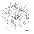
- the invention relates to a measuring arrangement 10, which is designed and set up for measuring strands 12 and / or strand sections which are produced in strand units 11 of the tobacco processing industry and which are separated from a strand 12 and form a strand 12 again in succession is.
- the measuring arrangement 10 comprises a measuring head 13 with at least two measuring modules 14.
- the measuring modules 14 form at least one measuring section which extends in the conveying direction F of the or each strand 12.
- continuous strand passage channel 15 is formed in the measuring head 13 at least one in the conveying direction F through the entire measuring head 13 and all measuring modules 14 extending.
- at least one strand guiding device 16 is assigned to the measuring head 13.
- the measuring head 13 or all associated measuring modules 14 are connected via connections to an evaluation unit 18.
- all the measuring modules 14 are arranged in a common housing 19 of the measuring head 13, wherein the measuring modules 14 can be plugged via electrical and / or pneumatic connectors 17 onto a module carrier 22 attached to a base plate 20 of the housing 19 and providing several slots 21 with at least partially free choice of slots are.
- the order of the measuring modules 14, in particular if they have a different measuring function, can vary as desired.
- Particularly preferred is a module carrier 22 with completely free choice of slots, so that the measuring modules 14 can be plugged into any slots 21 on the module carrier 22. It can also slots 21 remain free.
- the invention also relates to a measuring arrangement 10, which is used for measuring strands 12 produced in strand units 11 of the tobacco processing industry and transported in the conveying direction F and / or strand sections which are separated from a strand 12 and form a strand 12 again in succession.
- a measuring arrangement 10 which is used for measuring strands 12 produced in strand units 11 of the tobacco processing industry and transported in the conveying direction F and / or strand sections which are separated from a strand 12 and form a strand 12 again in succession.
- the or each measuring module 14 is arranged in a common housing 19 of the measuring head 13, wherein each measuring module 14 via electrical and / or pneumatic connectors 17 to a mounted on a bottom plate 20 of the housing 19 and at least two slots 21 providing module carrier 22 with at least partially free slot selection is pluggable, each module module-free slot 21 is equipped with a dummy module.
- Empty modules are in the broadest sense also measuring modules.
- the measuring modules 14 contain a measuring function with respect to the strand 12 and can therefore be used operationally.
- the dummy modules do not include a measurement function with respect to the strand and should serve as a kind of dummy or placeholder for a measurement module 14. One can therefore call the dummy modules as virtual measurement modules.
- a measuring arrangement 10 for measuring two strands 12 or strand sections running parallel to one another in the conveying direction F is shown.
- the housing 19 has, in addition to the bottom plate 20, which is designed as a module carrier 22, preferably four side walls 23, 24, 25, 26 and a lid not explicitly shown on the housing 19 to open and close, for example by folding or pushing ,
- the lid is designed to be hinged by means of at least one hinge.
- the side walls 23, 24 arranged in the conveying direction F on the input side and on the output side have, according to the number of strands 12 to be measured, openings 27 for the entry and exit of the or each strand 12 in the measuring assembly 10, wherein the openings 27, in the embodiment, two openings 27 are formed, the strand passage channel 15 and in the present embodiment, the two strand flow channels 15 continue.
- the openings 27 are preferably arranged eccentrically with respect to a central axis K of a measuring module 14 (see, for example, FIG FIG. 1 ), in order to be adapted to adjacent measuring modules 14 at the distance defined by the strand unit 11 between the two strands 12.
- the embodiment shown is designed to configure the measuring arrangement 10 in a so-called 7.2 arrangement.
- the module carrier 22 has four slots 21 in a 4.1 arrangement or eight slots 21 in a 4.2 arrangement.
- a single measuring module 14 is provided for each measuring section.
- the other three slots 21 of each measuring section are equipped to form a closed strand passage channel 15 with empty modules.
- These dummy modules can have electrical contacts, so that the complete assembly (of all slots 21) and / or the position of measuring modules 14 and dummy modules can be monitored.
- the term "measuring module” is also true for the dummy modules.
- the detection of whether a slot 21 is equipped at all and whether a slot 21 is equipped with a measuring module 14 or an empty module can be important for the self-configuration of the measuring arrangement 10.
- all plug-in connections 17 between the measuring modules 14 and / or the dummy modules and the module carrier 22 are designed as standardized interfaces for all measuring modules 14 independently of their measuring function.
- the plug and the corresponding slots 21 to form the connectors 17 can also Other line connections and / or contacts between measuring module 14 or dummy module and module carrier 22 may be provided. Due to the standardization of the plug-in connections 17, a plurality of measuring modules 14 with different measuring functions can be arranged in one measuring section.
- a plurality of measuring modules 14 with the same measuring function can also be arranged one behind the other in a measuring section.
- the respective free slots 21 can be equipped with the described dummy modules.
- the slots 21 are arranged on the module carrier 22 with a fixed pitch T one behind the other and / or next to each other. All slots 21 of a measuring section M 1 and M 2 have a pitch T 1 in the conveying direction F. This means that the distances between the individual slots 21 in each measuring section are the same. In the event that more than one measuring section is provided, in the example of FIG. 1 If two measuring sections M 1 and M 2 are provided, the pitch T 2 between adjacent measuring sections transverse to the conveying direction F is the same (see, for example, FIGS FIG. 4 ). The slots 21 of adjacent measuring sections can be aligned transversely to the conveying direction F.
- the slots 21 of adjacent measuring sections lie on a transverse line to the conveying direction F (imaginary) line.
- the slots 21 of adjacent measuring sections in the conveying direction F offset from one another.
- the slots are set 21 of adjacent measuring paths with a gap, preferably offset by the amount T1 / 2.
- all measuring modules 14 are identical regardless of their measurement function and / or all empty modules with respect to their outer geometry, the positioning of the plug and the positioning of the strand passage channel 15 forming strand passage channel portion, so that each measuring module 14 and / or each dummy module can be plugged onto any module carrier 22 and on each slot 21 of a module carrier 22, in any orientation.
- the measuring modules 14 and / or the dummy modules can be rotated by 180 ° twisted about its central axis K are placed on the module carrier 22, and then on the other measuring line.
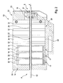
- a further preferred option consists in that a protective tube 29 extending in the conveying direction F from the side wall 23 to the side wall 24 of the housing 19 is arranged in each strand passage 15, wherein the protective tube 29 can be inserted into the housing 19 and withdrawn from the housing 19.
- This protective tube 29 is preferably releasably attached to the housing 19 and may be in operative connection with the lid. This means that the protective tube 29 triggers a locking of the lid, so that the lid can be opened only after removal of the protective tube 29.
- the material properties of the protective tube 29 are adapted to the present tasks of the measuring modules 14. Thus, optical, capacitive, stability and strength issues and antistatic u.a. To consider aspects. It is a single continuous tube, preferably made of an optical plastic, for example, cyclo-olefin (CO) polymers (COP / COC) used.
- CO cyclo-olefin
- each measuring module 14 and / or each empty module is assigned a protective tube section for forming a protective tube 29 extending from side wall 23 to side wall 24 of housing 19 and arranged within each strand passage channel 15, wherein the protective tube sections assigned to measuring modules 14 correspond to the measuring function of FIG respective measuring module 14 are adjusted.
- the protective tube 29 is designed in several parts, namely a plurality of protective tube sections.
- such a protective tube section is fixedly but detachably arranged in the strand passage channel (section) and shields measuring means of the measuring arrangement 10 from the or each strand 12 or strand section.
- the protective tube sections in particular those associated with a measuring module 14, can be adapted differently to the respective measuring device in the measuring module 14 for adaptation to the respective measuring function, for example with regard to the material selection and properties and / or the profile cross sections and / or the size and diameter be.
- a strand guiding device 16 is optionally arranged in the inlet region E and / or in the outlet region A of the or each strand 12 or strand section in the housing 19 or out of the housing 19 and / or in a middle section between the inlet region E and the outlet region A.
- at least one, but preferably each strand guide device 16 is formed as a radially adjustable multipoint storage.
- the strand guiding device 16 can also be designed as a simple and rigid guide. Due to the radially adjustable multipoint storage, for example, according to the principle of a three-jaw chuck, the strand guide device 16, however, is format-independent.
- Each strand guide device 16 may be formed separately from the housing 19. However, the or each strand guiding device 16 can also be arranged at all positions between the inlet region E and the outlet region A. However, the strand guiding devices 16 are preferably integrated into the side walls 23, 24 of the housing 19.
- the protective tube 29 may also be formed in several parts.
- the protective tube 29 has seams.
- sealing means for sealing a measuring module 14 and / or a dummy module against a in the conveying direction F subsequent measuring module 14 and / or empty module and / or a housing wall are provided.
- sealing means are preferably provided for active, that is controllable or variable, sealing. With the sealing means in particular adjacent, but spaced apart measuring modules 14 and / or dummy modules are sealed against each other or against an outer housing wall.
- the measuring arrangement 10 which comprises a cutting device 31.
- This cutting device 31 is arranged in the entry region E and can be designed as a module detachable from the housing 19 or as an integral part of the housing 19. In the latter case, the cutting device 31 may be an integral part of the side wall 23.
- the cutting device 31 can the strand 12 severed at standstill of the machine and also the strand passage channel 15 are closed on one side.
- the strand part remaining in the measuring head 13 can then be conveyed out and thus the measuring head 13 can be cleaned so that an automatic restart of the machine is ensured after a strand break.
- the side walls 23 to 26 may be integrally connected to each other.
- the side walls 23 to 26 may also be assembled modularly.
- the input-side side wall 23 with the integrated cutting device 31 may be releasably secured to the housing 19.
- one of the parallel to the conveying direction F extending side walls 25, 26 guide grooves 32 and / or guide rails or other guide means which correspond to corresponding projections 35 and / or recesses.
- a guide connection is made directly or indirectly between each measuring module 14 and / or each empty module and the housing 19.
- the measuring modules 14 and dummy modules of the rear measuring section M 1 comprising three measuring modules 14 and dummy modules, are guided directly on or in the housing 19 and more precisely in the side wall 26.
- the one measuring module 14 of the second measuring section M 2 is guided indirectly on the housing 19, namely via a measuring module 14 or empty module of the first measuring section M 1 .
- the lying in adjacent rows or measuring sections measuring modules 14 and / or dummy modules are guided to each other with the side faces facing each other, the guides between the measuring modules 14 and dummy modules with each other with the guides between the measuring modules 14 and dummy modules and the housing 19 identical are.
- FIG. 5 schematically a measuring arrangement 10 is shown, which is integrated into a string unit 11.
- the strand unit 11 is usually part of a stranding machine 33, to which, when configured as a tobacco rod making machine, a distributor unit 34 (see FIG FIG. 5 ) and in a training as a filter rod machine include a filter tow conditioning unit.
- a stranding machine 33 to which, when configured as a tobacco rod making machine, a distributor unit 34 (see FIG FIG. 5 ) and in a training as a filter rod machine include a filter tow conditioning unit.
- Such stranding machines 33 and strand units 11 are well known, for which reason a detailed description is dispensed with.
- the string unit 11 according to the invention is characterized in that the measuring arrangement 10 described above is inserted into the string unit 11 and thus into the string unit 11 Production is integrated, so that an online measurement with rapidly changing configuration of the measuring device 10 is achieved.
- another linear guide system can be used instead of the guide rails 30, another linear guide system. Due to the mobility of the housing 19 is virtually created a drawer system, such that the housing 19 can be preferred from the working position. In this early maintenance position, maintenance and retooling, as well as reconfigurations or reconfigurations on the measuring assembly 10 can be easily performed on the machine.
- the housing 19 is preferably lockable in the working position. After releasing the lock, the housing 19 may be pulled forward to the maintenance position to provide free access to the measurement assembly 10 and in particular to the measurement modules 14 and / or the dummy modules. In the maintenance position, the measuring arrangement 10 and in particular the protective tube 29 can be cleaned or pulled out of the strand passage channel 15. After removal of the protective tube 29, the lid of the housing 19 can be opened and releases the measuring modules 14 or empty modules for configuring the module carrier 22.
- this procedure is only described by way of example.
- the housing 19 is releasably secured to the string unit 11 adjacent to the cutter 31 or other cutting means.
- the housing 19 comprises a cover which is mounted parallel to the conveying direction F of the or each strand 12 or strand section and can be removed or opened without tools.
- the housing 19 comprises electrical contacts, by means of which the voltage supply to the module carrier 22 can be interrupted when opening the housing 19.
Landscapes
- Physics & Mathematics (AREA)
- Health & Medical Sciences (AREA)
- Life Sciences & Earth Sciences (AREA)
- Chemical & Material Sciences (AREA)
- Analytical Chemistry (AREA)
- Biochemistry (AREA)
- General Health & Medical Sciences (AREA)
- General Physics & Mathematics (AREA)
- Immunology (AREA)
- Pathology (AREA)
- Manufacturing Of Cigar And Cigarette Tobacco (AREA)
- Measuring Or Testing Involving Enzymes Or Micro-Organisms (AREA)
- Cigarettes, Filters, And Manufacturing Of Filters (AREA)
Priority Applications (1)
| Application Number | Priority Date | Filing Date | Title |
|---|---|---|---|
| PL13159871T PL2641489T3 (pl) | 2012-03-20 | 2013-03-19 | Układ pomiarowy, zaprojektowany i przystosowany do mierzenia pasm i/lub odcinków pasm wytworzonych w zespołach do wytwarzania pasm przemysłu przetwórstwa tytoniu oraz zespół do wytwarzania pasm z takim układem pomiarowym |
Applications Claiming Priority (2)
| Application Number | Priority Date | Filing Date | Title |
|---|---|---|---|
| DE201210102340 DE102012102340A1 (de) | 2012-03-20 | 2012-03-20 | Messanordnung, ausgebildet und eingerichtet zum Messen von in Strangeinheiten der Tabak verarbeitenden Industrie hergestellten Strängen und/oder Strangabschnitten sowie Strangeinheit mit einer solchen Messanordnung |
| DE102012105121A DE102012105121A1 (de) | 2012-06-13 | 2012-06-13 | Messmodul und Messanordnung zum Messen von in Strangmaschinen der Tabak verarbeitenden Industrie hergestellten Strängen und/oder Strangabschnitten sowie Strangmaschine mit solchen Messmodulen bzw. einer solchen Messanordnung |
Publications (3)
| Publication Number | Publication Date |
|---|---|
| EP2641489A2 true EP2641489A2 (fr) | 2013-09-25 |
| EP2641489A3 EP2641489A3 (fr) | 2017-05-10 |
| EP2641489B1 EP2641489B1 (fr) | 2018-09-26 |
Family
ID=47997050
Family Applications (1)
| Application Number | Title | Priority Date | Filing Date |
|---|---|---|---|
| EP13159871.6A Active EP2641489B1 (fr) | 2012-03-20 | 2013-03-19 | Dispositif de mesure, conçu pour et destiné à la mesure de tiges et/ou de sections de tige fabriquées dans des unités de fabrication de tiges de l'industrie de traitement du tabac ainsi qu'unité de fabrication de tiges dotée d'un tel dispositif de mesure |
Country Status (4)
| Country | Link |
|---|---|
| EP (1) | EP2641489B1 (fr) |
| JP (1) | JP2013192561A (fr) |
| CN (1) | CN103315392B (fr) |
| PL (1) | PL2641489T3 (fr) |
Cited By (2)
| Publication number | Priority date | Publication date | Assignee | Title |
|---|---|---|---|---|
| DE102014222465A1 (de) | 2014-11-04 | 2016-05-04 | Hauni Maschinenbau Ag | Verfahren zum Überwachen eines modularen Messsystems sowie Leermodul, modulares Messsystem und Strangmaschine der Tabak verarbeitenden Industrie |
| EP3161476B1 (fr) | 2015-03-20 | 2017-11-15 | Uster Technologies AG | Appareil modulaire de contrôle de fil |
Families Citing this family (1)
| Publication number | Priority date | Publication date | Assignee | Title |
|---|---|---|---|---|
| CN113777231A (zh) * | 2021-08-20 | 2021-12-10 | 中国原子能科学研究院 | 一种探测器安装装置及探测设备 |
Citations (2)
| Publication number | Priority date | Publication date | Assignee | Title |
|---|---|---|---|---|
| EP1516545A1 (fr) | 2003-09-16 | 2005-03-23 | Hauni Maschinbau AG | Machine et procédé pour la fabrication simultanée de plusieurs tiges de cigarette |
| WO2011083406A2 (fr) | 2010-01-07 | 2011-07-14 | Aiger Group Ag | Procédé, système et appareil pour l'inscription de différents objets dans des articles en forme de baguettes |
Family Cites Families (11)
| Publication number | Priority date | Publication date | Assignee | Title |
|---|---|---|---|---|
| ZA773860B (en) * | 1976-07-19 | 1978-06-28 | Westinghouse Electric Corp | An improvement in or relating to automatic transfer control device |
| DE3414247C2 (de) * | 1983-04-30 | 1994-09-08 | Hauni Werke Koerber & Co Kg | Vorrichtung zum Messen des Durchmessers von strang- oder stabförmigen Erzeugnissen der tabakverarbeitenden Industrie |
| DE3933647A1 (de) | 1989-10-08 | 1991-04-11 | Asea Brown Boveri | Messgeraet mit einem gehaeuse fuer steckbaugruppen |
| DE19546952C2 (de) | 1994-12-17 | 1999-06-17 | Horiba Ltd | Gasanalysator-Einschubanordnung |
| DE10137671A1 (de) * | 2001-08-01 | 2003-02-20 | S W A C Schmitt Walter Automat | Verfahren und Vorrichtung zur Überwachung einer insbesondere speicherprogrammierbaren Steuerung |
| DE10203095A1 (de) * | 2002-01-25 | 2003-07-31 | Hauni Maschinenbau Ag | Verfahren und Vorrichtung zum Messen des Durchmessers von Zigarettenstrang- oder stabförmigen Erzeugnissen der Tabak verarbeitenden Industrie |
| GB0306468D0 (en) * | 2003-03-20 | 2003-04-23 | Molins Plc | A method and apparatus for determining one or more physical properties of a rolled smoking article or filter rod |
| DE102004057092A1 (de) * | 2004-11-25 | 2006-06-01 | Hauni Maschinenbau Ag | Messen des Durchmessers von stabförmigen Artikeln der Tabak verarbeitenden Industrie |
| GB2424484B (en) | 2005-03-24 | 2009-10-07 | Molins Plc | Analysing equipment |
| DE102005046581A1 (de) * | 2005-09-28 | 2007-03-29 | Hauni Maschinenbau Ag | Einrichtung und Verfahren zum Messen von Eigenschaften von Multisegmentfiltern oder Zusammenstellungen von Filtersegmenten |
| DE102009058040B4 (de) * | 2009-12-14 | 2012-11-29 | Hauni Maschinenbau Ag | Maschine und Verfahren zum Herstellen von Filterstäben für die Tabak verarbeitende Industrie |
-
2013
- 2013-03-19 PL PL13159871T patent/PL2641489T3/pl unknown
- 2013-03-19 EP EP13159871.6A patent/EP2641489B1/fr active Active
- 2013-03-19 JP JP2013055868A patent/JP2013192561A/ja active Pending
- 2013-03-19 CN CN201310088074.0A patent/CN103315392B/zh active Active
Patent Citations (2)
| Publication number | Priority date | Publication date | Assignee | Title |
|---|---|---|---|---|
| EP1516545A1 (fr) | 2003-09-16 | 2005-03-23 | Hauni Maschinbau AG | Machine et procédé pour la fabrication simultanée de plusieurs tiges de cigarette |
| WO2011083406A2 (fr) | 2010-01-07 | 2011-07-14 | Aiger Group Ag | Procédé, système et appareil pour l'inscription de différents objets dans des articles en forme de baguettes |
Cited By (3)
| Publication number | Priority date | Publication date | Assignee | Title |
|---|---|---|---|---|
| DE102014222465A1 (de) | 2014-11-04 | 2016-05-04 | Hauni Maschinenbau Ag | Verfahren zum Überwachen eines modularen Messsystems sowie Leermodul, modulares Messsystem und Strangmaschine der Tabak verarbeitenden Industrie |
| EP3161476B1 (fr) | 2015-03-20 | 2017-11-15 | Uster Technologies AG | Appareil modulaire de contrôle de fil |
| EP3161476B2 (fr) † | 2015-03-20 | 2022-07-20 | Uster Technologies AG | Appareil modulaire de contrôle de fil |
Also Published As
| Publication number | Publication date |
|---|---|
| EP2641489B1 (fr) | 2018-09-26 |
| CN103315392A (zh) | 2013-09-25 |
| JP2013192561A (ja) | 2013-09-30 |
| PL2641489T3 (pl) | 2019-04-30 |
| CN103315392B (zh) | 2016-06-22 |
| EP2641489A3 (fr) | 2017-05-10 |
Similar Documents
| Publication | Publication Date | Title |
|---|---|---|
| EP2641487B9 (fr) | Dispositif de mesure de tiges et/ou de sections de tige ainsi qu'unité de fabrication de tiges dotée d'un tel dispositif de mesure et procédé de mesure | |
| EP1847186B1 (fr) | Unité de préparation destinée à la préparation d'au moins une bande de cordon filtrant pour la fabrication de filtre pour les articles à fumer en forme de tige | |
| DE2826539C2 (de) | Zigarettenzuführvorrichtung | |
| EP1847187B1 (fr) | Unité de préparation destinée à la préparation d'au moins une bande de filtre tout comme un dispositif doté d'au moins deux telles unités de préparation | |
| DE102011085981A1 (de) | Filterherstellmaschine der Tabak verarbeitenden Industrie | |
| EP0828598B1 (fr) | Dispositif changeur de tamis pour installations de transformation de matieres plastiques | |
| EP2674045B1 (fr) | Module de mesure et dispositif de mesure pour la mesure de tiges et/ou de sections de tige fabriquées dans des machines de fabrication de tiges de l'industrie de traitement du tabac ainsi que machines de fabrication de tiges dotées de tels modules de mesure ou d'un tel dispositif de mesure | |
| EP2641489B1 (fr) | Dispositif de mesure, conçu pour et destiné à la mesure de tiges et/ou de sections de tige fabriquées dans des unités de fabrication de tiges de l'industrie de traitement du tabac ainsi qu'unité de fabrication de tiges dotée d'un tel dispositif de mesure | |
| DE102014009690A1 (de) | Vorrichtung in der Spinnereivorbereitung, Ginnerei o. dgl. zum Erkennen und Ausscheiden von Fremdstoffen in oder zwischen Fasermaterial, insbesondere Baumwolle | |
| DE3509711C2 (de) | Vorrichtung zur Zufuhr von Zigaretten zur Umhüllungsstrecke einer Verpackungsmaschine | |
| DE69100570T2 (de) | Zurückhalteverfahren und -vorrichtung für einen Ausgabetrichter, insbesondere zum Ausgeben von Zigaretten. | |
| DE19607783C2 (de) | Werkzeugmaschine mit einer Anzahl von Schmierstellen | |
| EP2815657B1 (fr) | Machine de l'industrie de traitement du tabac, en particulier machine d'assemblage de filtres | |
| DE102011010257A9 (de) | Anordnung und Verfahren zum Produzieren und Speichern stabförmiger Halbfertigprodukte der Tabak verarbeitenden Industrie | |
| DE102012102340A1 (de) | Messanordnung, ausgebildet und eingerichtet zum Messen von in Strangeinheiten der Tabak verarbeitenden Industrie hergestellten Strängen und/oder Strangabschnitten sowie Strangeinheit mit einer solchen Messanordnung | |
| EP2508086B2 (fr) | Dispositif de guidage de tige, agencement de mesure avec ce dispositif de guidage de tige et machine de fabrication de tiges avec dispositif de guidage de tige et/ou agencement de mesure | |
| EP2594630B1 (fr) | Dispositif de répartition pour un agencement d'exposition d'échantillons | |
| EP1488712B1 (fr) | Séparateur pour un flux de produit dans un distributeur | |
| EP3220110B1 (fr) | Dispositif de pesage avec armoire de distribution | |
| EP2496875A1 (fr) | Distributeur de lubrifiant | |
| DE102024002690A1 (de) | System | |
| EP1516548B1 (fr) | Dispositif de répartition pour une machine de l'industrie du tabac |
Legal Events
| Date | Code | Title | Description |
|---|---|---|---|
| PUAI | Public reference made under article 153(3) epc to a published international application that has entered the european phase |
Free format text: ORIGINAL CODE: 0009012 |
|
| AK | Designated contracting states |
Kind code of ref document: A2 Designated state(s): AL AT BE BG CH CY CZ DE DK EE ES FI FR GB GR HR HU IE IS IT LI LT LU LV MC MK MT NL NO PL PT RO RS SE SI SK SM TR |
|
| AX | Request for extension of the european patent |
Extension state: BA ME |
|
| RAP1 | Party data changed (applicant data changed or rights of an application transferred) |
Owner name: HAUNI MASCHINENBAU GMBH |
|
| PUAL | Search report despatched |
Free format text: ORIGINAL CODE: 0009013 |
|
| AK | Designated contracting states |
Kind code of ref document: A3 Designated state(s): AL AT BE BG CH CY CZ DE DK EE ES FI FR GB GR HR HU IE IS IT LI LT LU LV MC MK MT NL NO PL PT RO RS SE SI SK SM TR |
|
| AX | Request for extension of the european patent |
Extension state: BA ME |
|
| RIC1 | Information provided on ipc code assigned before grant |
Ipc: A24C 5/34 20060101AFI20170406BHEP Ipc: G01N 35/00 20060101ALN20170406BHEP Ipc: G01N 21/952 20060101ALI20170406BHEP |
|
| STAA | Information on the status of an ep patent application or granted ep patent |
Free format text: STATUS: REQUEST FOR EXAMINATION WAS MADE |
|
| 17P | Request for examination filed |
Effective date: 20171109 |
|
| RBV | Designated contracting states (corrected) |
Designated state(s): AL AT BE BG CH CY CZ DE DK EE ES FI FR GB GR HR HU IE IS IT LI LT LU LV MC MK MT NL NO PL PT RO RS SE SI SK SM TR |
|
| RIC1 | Information provided on ipc code assigned before grant |
Ipc: A24C 5/34 20060101AFI20180228BHEP Ipc: G01N 21/952 20060101ALI20180228BHEP Ipc: G01N 35/00 20060101ALN20180228BHEP |
|
| GRAP | Despatch of communication of intention to grant a patent |
Free format text: ORIGINAL CODE: EPIDOSNIGR1 |
|
| STAA | Information on the status of an ep patent application or granted ep patent |
Free format text: STATUS: GRANT OF PATENT IS INTENDED |
|
| INTG | Intention to grant announced |
Effective date: 20180410 |
|
| GRAS | Grant fee paid |
Free format text: ORIGINAL CODE: EPIDOSNIGR3 |
|
| GRAA | (expected) grant |
Free format text: ORIGINAL CODE: 0009210 |
|
| STAA | Information on the status of an ep patent application or granted ep patent |
Free format text: STATUS: THE PATENT HAS BEEN GRANTED |
|
| AK | Designated contracting states |
Kind code of ref document: B1 Designated state(s): AL AT BE BG CH CY CZ DE DK EE ES FI FR GB GR HR HU IE IS IT LI LT LU LV MC MK MT NL NO PL PT RO RS SE SI SK SM TR |
|
| REG | Reference to a national code |
Ref country code: GB Ref legal event code: FG4D Free format text: NOT ENGLISH |
|
| REG | Reference to a national code |
Ref country code: CH Ref legal event code: EP |
|
| REG | Reference to a national code |
Ref country code: AT Ref legal event code: REF Ref document number: 1044957 Country of ref document: AT Kind code of ref document: T Effective date: 20181015 |
|
| REG | Reference to a national code |
Ref country code: IE Ref legal event code: FG4D Free format text: LANGUAGE OF EP DOCUMENT: GERMAN |
|
| REG | Reference to a national code |
Ref country code: DE Ref legal event code: R096 Ref document number: 502013011152 Country of ref document: DE |
|
| REG | Reference to a national code |
Ref country code: NL Ref legal event code: FP |
|
| PG25 | Lapsed in a contracting state [announced via postgrant information from national office to epo] |
Ref country code: BG Free format text: LAPSE BECAUSE OF FAILURE TO SUBMIT A TRANSLATION OF THE DESCRIPTION OR TO PAY THE FEE WITHIN THE PRESCRIBED TIME-LIMIT Effective date: 20181226 Ref country code: LT Free format text: LAPSE BECAUSE OF FAILURE TO SUBMIT A TRANSLATION OF THE DESCRIPTION OR TO PAY THE FEE WITHIN THE PRESCRIBED TIME-LIMIT Effective date: 20180926 Ref country code: SE Free format text: LAPSE BECAUSE OF FAILURE TO SUBMIT A TRANSLATION OF THE DESCRIPTION OR TO PAY THE FEE WITHIN THE PRESCRIBED TIME-LIMIT Effective date: 20180926 Ref country code: GR Free format text: LAPSE BECAUSE OF FAILURE TO SUBMIT A TRANSLATION OF THE DESCRIPTION OR TO PAY THE FEE WITHIN THE PRESCRIBED TIME-LIMIT Effective date: 20181227 Ref country code: NO Free format text: LAPSE BECAUSE OF FAILURE TO SUBMIT A TRANSLATION OF THE DESCRIPTION OR TO PAY THE FEE WITHIN THE PRESCRIBED TIME-LIMIT Effective date: 20181226 Ref country code: FI Free format text: LAPSE BECAUSE OF FAILURE TO SUBMIT A TRANSLATION OF THE DESCRIPTION OR TO PAY THE FEE WITHIN THE PRESCRIBED TIME-LIMIT Effective date: 20180926 Ref country code: RS Free format text: LAPSE BECAUSE OF FAILURE TO SUBMIT A TRANSLATION OF THE DESCRIPTION OR TO PAY THE FEE WITHIN THE PRESCRIBED TIME-LIMIT Effective date: 20180926 |
|
| REG | Reference to a national code |
Ref country code: LT Ref legal event code: MG4D |
|
| PG25 | Lapsed in a contracting state [announced via postgrant information from national office to epo] |
Ref country code: HR Free format text: LAPSE BECAUSE OF FAILURE TO SUBMIT A TRANSLATION OF THE DESCRIPTION OR TO PAY THE FEE WITHIN THE PRESCRIBED TIME-LIMIT Effective date: 20180926 Ref country code: LV Free format text: LAPSE BECAUSE OF FAILURE TO SUBMIT A TRANSLATION OF THE DESCRIPTION OR TO PAY THE FEE WITHIN THE PRESCRIBED TIME-LIMIT Effective date: 20180926 Ref country code: AL Free format text: LAPSE BECAUSE OF FAILURE TO SUBMIT A TRANSLATION OF THE DESCRIPTION OR TO PAY THE FEE WITHIN THE PRESCRIBED TIME-LIMIT Effective date: 20180926 |
|
| PG25 | Lapsed in a contracting state [announced via postgrant information from national office to epo] |
Ref country code: IS Free format text: LAPSE BECAUSE OF FAILURE TO SUBMIT A TRANSLATION OF THE DESCRIPTION OR TO PAY THE FEE WITHIN THE PRESCRIBED TIME-LIMIT Effective date: 20190126 Ref country code: EE Free format text: LAPSE BECAUSE OF FAILURE TO SUBMIT A TRANSLATION OF THE DESCRIPTION OR TO PAY THE FEE WITHIN THE PRESCRIBED TIME-LIMIT Effective date: 20180926 Ref country code: CZ Free format text: LAPSE BECAUSE OF FAILURE TO SUBMIT A TRANSLATION OF THE DESCRIPTION OR TO PAY THE FEE WITHIN THE PRESCRIBED TIME-LIMIT Effective date: 20180926 Ref country code: RO Free format text: LAPSE BECAUSE OF FAILURE TO SUBMIT A TRANSLATION OF THE DESCRIPTION OR TO PAY THE FEE WITHIN THE PRESCRIBED TIME-LIMIT Effective date: 20180926 Ref country code: ES Free format text: LAPSE BECAUSE OF FAILURE TO SUBMIT A TRANSLATION OF THE DESCRIPTION OR TO PAY THE FEE WITHIN THE PRESCRIBED TIME-LIMIT Effective date: 20180926 |
|
| PG25 | Lapsed in a contracting state [announced via postgrant information from national office to epo] |
Ref country code: PT Free format text: LAPSE BECAUSE OF FAILURE TO SUBMIT A TRANSLATION OF THE DESCRIPTION OR TO PAY THE FEE WITHIN THE PRESCRIBED TIME-LIMIT Effective date: 20190126 Ref country code: SM Free format text: LAPSE BECAUSE OF FAILURE TO SUBMIT A TRANSLATION OF THE DESCRIPTION OR TO PAY THE FEE WITHIN THE PRESCRIBED TIME-LIMIT Effective date: 20180926 Ref country code: SK Free format text: LAPSE BECAUSE OF FAILURE TO SUBMIT A TRANSLATION OF THE DESCRIPTION OR TO PAY THE FEE WITHIN THE PRESCRIBED TIME-LIMIT Effective date: 20180926 |
|
| REG | Reference to a national code |
Ref country code: DE Ref legal event code: R026 Ref document number: 502013011152 Country of ref document: DE |
|
| PLBI | Opposition filed |
Free format text: ORIGINAL CODE: 0009260 |
|
| PLAX | Notice of opposition and request to file observation + time limit sent |
Free format text: ORIGINAL CODE: EPIDOSNOBS2 |
|
| PG25 | Lapsed in a contracting state [announced via postgrant information from national office to epo] |
Ref country code: DK Free format text: LAPSE BECAUSE OF FAILURE TO SUBMIT A TRANSLATION OF THE DESCRIPTION OR TO PAY THE FEE WITHIN THE PRESCRIBED TIME-LIMIT Effective date: 20180926 |
|
| 26 | Opposition filed |
Opponent name: G.D SOCIETA PER AZIONI Effective date: 20190626 |
|
| PG25 | Lapsed in a contracting state [announced via postgrant information from national office to epo] |
Ref country code: SI Free format text: LAPSE BECAUSE OF FAILURE TO SUBMIT A TRANSLATION OF THE DESCRIPTION OR TO PAY THE FEE WITHIN THE PRESCRIBED TIME-LIMIT Effective date: 20180926 Ref country code: MC Free format text: LAPSE BECAUSE OF FAILURE TO SUBMIT A TRANSLATION OF THE DESCRIPTION OR TO PAY THE FEE WITHIN THE PRESCRIBED TIME-LIMIT Effective date: 20180926 |
|
| REG | Reference to a national code |
Ref country code: CH Ref legal event code: PL |
|
| PLBB | Reply of patent proprietor to notice(s) of opposition received |
Free format text: ORIGINAL CODE: EPIDOSNOBS3 |
|
| PG25 | Lapsed in a contracting state [announced via postgrant information from national office to epo] |
Ref country code: LU Free format text: LAPSE BECAUSE OF NON-PAYMENT OF DUE FEES Effective date: 20190319 |
|
| REG | Reference to a national code |
Ref country code: BE Ref legal event code: MM Effective date: 20190331 |
|
| PG25 | Lapsed in a contracting state [announced via postgrant information from national office to epo] |
Ref country code: CH Free format text: LAPSE BECAUSE OF NON-PAYMENT OF DUE FEES Effective date: 20190331 Ref country code: LI Free format text: LAPSE BECAUSE OF NON-PAYMENT OF DUE FEES Effective date: 20190331 Ref country code: IE Free format text: LAPSE BECAUSE OF NON-PAYMENT OF DUE FEES Effective date: 20190319 |
|
| PG25 | Lapsed in a contracting state [announced via postgrant information from national office to epo] |
Ref country code: FR Free format text: LAPSE BECAUSE OF NON-PAYMENT OF DUE FEES Effective date: 20190331 Ref country code: BE Free format text: LAPSE BECAUSE OF NON-PAYMENT OF DUE FEES Effective date: 20190331 |
|
| PG25 | Lapsed in a contracting state [announced via postgrant information from national office to epo] |
Ref country code: TR Free format text: LAPSE BECAUSE OF FAILURE TO SUBMIT A TRANSLATION OF THE DESCRIPTION OR TO PAY THE FEE WITHIN THE PRESCRIBED TIME-LIMIT Effective date: 20180926 |
|
| PG25 | Lapsed in a contracting state [announced via postgrant information from national office to epo] |
Ref country code: MT Free format text: LAPSE BECAUSE OF FAILURE TO SUBMIT A TRANSLATION OF THE DESCRIPTION OR TO PAY THE FEE WITHIN THE PRESCRIBED TIME-LIMIT Effective date: 20180926 |
|
| REG | Reference to a national code |
Ref country code: AT Ref legal event code: MM01 Ref document number: 1044957 Country of ref document: AT Kind code of ref document: T Effective date: 20190319 |
|
| PG25 | Lapsed in a contracting state [announced via postgrant information from national office to epo] |
Ref country code: AT Free format text: LAPSE BECAUSE OF NON-PAYMENT OF DUE FEES Effective date: 20190319 |
|
| PLCK | Communication despatched that opposition was rejected |
Free format text: ORIGINAL CODE: EPIDOSNREJ1 |
|
| PG25 | Lapsed in a contracting state [announced via postgrant information from national office to epo] |
Ref country code: CY Free format text: LAPSE BECAUSE OF FAILURE TO SUBMIT A TRANSLATION OF THE DESCRIPTION OR TO PAY THE FEE WITHIN THE PRESCRIBED TIME-LIMIT Effective date: 20180926 |
|
| APBM | Appeal reference recorded |
Free format text: ORIGINAL CODE: EPIDOSNREFNO |
|
| APBP | Date of receipt of notice of appeal recorded |
Free format text: ORIGINAL CODE: EPIDOSNNOA2O |
|
| APAH | Appeal reference modified |
Free format text: ORIGINAL CODE: EPIDOSCREFNO |
|
| PG25 | Lapsed in a contracting state [announced via postgrant information from national office to epo] |
Ref country code: HU Free format text: LAPSE BECAUSE OF FAILURE TO SUBMIT A TRANSLATION OF THE DESCRIPTION OR TO PAY THE FEE WITHIN THE PRESCRIBED TIME-LIMIT; INVALID AB INITIO Effective date: 20130319 |
|
| APBQ | Date of receipt of statement of grounds of appeal recorded |
Free format text: ORIGINAL CODE: EPIDOSNNOA3O |
|
| PG25 | Lapsed in a contracting state [announced via postgrant information from national office to epo] |
Ref country code: MK Free format text: LAPSE BECAUSE OF FAILURE TO SUBMIT A TRANSLATION OF THE DESCRIPTION OR TO PAY THE FEE WITHIN THE PRESCRIBED TIME-LIMIT Effective date: 20180926 |
|
| REG | Reference to a national code |
Ref country code: DE Ref legal event code: R081 Ref document number: 502013011152 Country of ref document: DE Owner name: KOERBER TECHNOLOGIES GMBH, DE Free format text: FORMER OWNER: HAUNI MASCHINENBAU GMBH, 21033 HAMBURG, DE |
|
| REG | Reference to a national code |
Ref country code: NL Ref legal event code: HC Owner name: KOERBER TECHNOLOGIES GMBH; DE Free format text: DETAILS ASSIGNMENT: CHANGE OF OWNER(S), CHANGE OF OWNER(S) NAME; FORMER OWNER NAME: HAUNI MASCHINENBAU GMBH Effective date: 20221020 |
|
| RAP4 | Party data changed (patent owner data changed or rights of a patent transferred) |
Owner name: KOERBER TECHNOLOGIES GMBH |
|
| REG | Reference to a national code |
Ref country code: DE Ref legal event code: R100 Ref document number: 502013011152 Country of ref document: DE |
|
| APBU | Appeal procedure closed |
Free format text: ORIGINAL CODE: EPIDOSNNOA9O |
|
| PLBN | Opposition rejected |
Free format text: ORIGINAL CODE: 0009273 |
|
| STAA | Information on the status of an ep patent application or granted ep patent |
Free format text: STATUS: OPPOSITION REJECTED |
|
| 27O | Opposition rejected |
Effective date: 20230130 |
|
| P01 | Opt-out of the competence of the unified patent court (upc) registered |
Effective date: 20230616 |
|
| PGFP | Annual fee paid to national office [announced via postgrant information from national office to epo] |
Ref country code: DE Payment date: 20250331 Year of fee payment: 13 |
|
| PGFP | Annual fee paid to national office [announced via postgrant information from national office to epo] |
Ref country code: IT Payment date: 20250327 Year of fee payment: 13 |
|
| PGFP | Annual fee paid to national office [announced via postgrant information from national office to epo] |
Ref country code: GB Payment date: 20260330 Year of fee payment: 14 |
|
| PGFP | Annual fee paid to national office [announced via postgrant information from national office to epo] |
Ref country code: NL Payment date: 20260330 Year of fee payment: 14 |
|
| PGFP | Annual fee paid to national office [announced via postgrant information from national office to epo] |
Ref country code: PL Payment date: 20260220 Year of fee payment: 14 |