EP2642085B1 - Dispositif d'inspection pour moteur à turbine à gas - Google Patents
Dispositif d'inspection pour moteur à turbine à gas Download PDFInfo
- Publication number
- EP2642085B1 EP2642085B1 EP13157988.0A EP13157988A EP2642085B1 EP 2642085 B1 EP2642085 B1 EP 2642085B1 EP 13157988 A EP13157988 A EP 13157988A EP 2642085 B1 EP2642085 B1 EP 2642085B1
- Authority
- EP
- European Patent Office
- Prior art keywords
- shutter
- inspection device
- gas turbine
- turbine engine
- inspection
- Prior art date
- Legal status (The legal status is an assumption and is not a legal conclusion. Google has not performed a legal analysis and makes no representation as to the accuracy of the status listed.)
- Active
Links
Images

Classifications
-
- F—MECHANICAL ENGINEERING; LIGHTING; HEATING; WEAPONS; BLASTING
- F02—COMBUSTION ENGINES; HOT-GAS OR COMBUSTION-PRODUCT ENGINE PLANTS
- F02C—GAS-TURBINE PLANTS; AIR INTAKES FOR JET-PROPULSION PLANTS; CONTROLLING FUEL SUPPLY IN AIR-BREATHING JET-PROPULSION PLANTS
- F02C7/00—Features, components parts, details or accessories, not provided for in, or of interest apart form groups F02C1/00 - F02C6/00; Air intakes for jet-propulsion plants
-
- F—MECHANICAL ENGINEERING; LIGHTING; HEATING; WEAPONS; BLASTING
- F01—MACHINES OR ENGINES IN GENERAL; ENGINE PLANTS IN GENERAL; STEAM ENGINES
- F01D—NON-POSITIVE DISPLACEMENT MACHINES OR ENGINES, e.g. STEAM TURBINES
- F01D21/00—Shutting-down of machines or engines, e.g. in emergency; Regulating, controlling, or safety means not otherwise provided for
- F01D21/003—Arrangements for testing or measuring
-
- G—PHYSICS
- G01—MEASURING; TESTING
- G01N—INVESTIGATING OR ANALYSING MATERIALS BY DETERMINING THEIR CHEMICAL OR PHYSICAL PROPERTIES
- G01N21/00—Investigating or analysing materials by the use of optical means, i.e. using sub-millimetre waves, infrared, visible or ultraviolet light
- G01N21/84—Systems specially adapted for particular applications
- G01N21/88—Investigating the presence of flaws or contamination
- G01N21/95—Investigating the presence of flaws or contamination characterised by the material or shape of the object to be examined
- G01N21/954—Inspecting the inner surface of hollow bodies, e.g. bores
-
- F—MECHANICAL ENGINEERING; LIGHTING; HEATING; WEAPONS; BLASTING
- F05—INDEXING SCHEMES RELATING TO ENGINES OR PUMPS IN VARIOUS SUBCLASSES OF CLASSES F01-F04
- F05D—INDEXING SCHEME FOR ASPECTS RELATING TO NON-POSITIVE-DISPLACEMENT MACHINES OR ENGINES, GAS-TURBINES OR JET-PROPULSION PLANTS
- F05D2260/00—Function
- F05D2260/80—Diagnostics
-
- F—MECHANICAL ENGINEERING; LIGHTING; HEATING; WEAPONS; BLASTING
- F05—INDEXING SCHEMES RELATING TO ENGINES OR PUMPS IN VARIOUS SUBCLASSES OF CLASSES F01-F04
- F05D—INDEXING SCHEME FOR ASPECTS RELATING TO NON-POSITIVE-DISPLACEMENT MACHINES OR ENGINES, GAS-TURBINES OR JET-PROPULSION PLANTS
- F05D2270/00—Control
- F05D2270/80—Devices generating input signals, e.g. transducers, sensors, cameras or strain gauges
- F05D2270/804—Optical devices
Definitions
- This invention relates to an inspection device for a gas turbine engine.
- Figure 1 shows a ducted fan gas turbine engine 10 comprising, in axial flow series: an air intake 12, a propulsive fan 14 having a plurality of fan blades 16, an intermediate pressure compressor 18, a high-pressure compressor 20, a combustor 22, a high-pressure turbine 24, an intermediate pressure turbine 26, a low-pressure turbine 28 and a core exhaust nozzle 30.
- a nacelle 32 generally surrounds the engine 10 and defines the intake 12, a bypass duct 34 and a bypass exhaust nozzle 36.
- Air entering the intake 12 is accelerated by the fan 14 to produce a bypass flow and a core flow.
- the bypass flow travels down the bypass duct 34 and exits the bypass exhaust nozzle 36 to provide the majority of the propulsive thrust produced by the engine 10.
- the core flow enters in axial flow series the intermediate pressure compressor 18, high pressure compressor 20 and the combustor 22, where fuel is added to the compressed air and the mixture burnt.
- the hot combustion products expand through and drive the high, intermediate and low-pressure turbines 24, 26, 28 before being exhausted through the nozzle 30 to provide additional propulsive thrust.
- the high, intermediate and low-pressure turbines 24, 26, 28 respectively drive the high and intermediate pressure compressors 20, 18 and the fan 14 by interconnecting shafts 38, 40, 42.
- FIG. 2 shows such a port 210 for a compressor 18 which includes an outer casing wall 212 and an inner casing wall 214 which house annular arrays of compressor rotor blades 216 and stator vanes 218.
- the port 210 includes flanged apertures 220, 222 through the inner 214 and outer 212 walls and is shown in a closed configuration in which the apertures 220, 222 are sealed with a plug 224.
- the plug 224 constitutes sealing members 226, 228 for the inner and outer wall apertures 220, 222 which are linked by a link rod 230.
- the plug 224 can be realisably secured within the port 210 in any suitable manner and configured to be removed from the exterior of the compressor 18 when horoscope access is required. As will be appreciated, once removed, a horoscope can be inserted as required.
- the inspection ports 210 are located around the engine core so that, for example, each stage of the compressor 18 may have a circumferential distribution of inspection ports, as might the combustor or various turbine stages.
- US466297 describes a dual spectra optical pyrometer having an air pressure sensitive shutter for measuring the temperature of turbine blade and includes a sight tube located in the jet engine for receiving an optical beam from the turbine blade. Located within the sight tube is a shutter responsive to the jet engine air pressure so as to provide the turbine blade optical beam only above a selected threshold magnitude of air pressure.
- a detection module receives and divides the turbine blade optical beam and provides signals to a signal processer. From these signals and signals indicative of an estimated fireball equivalent black body temperature and the spectral width difference between the two detector signals, the signal processor provides a signal indicative of a compensated turbine blade temperature. Inspection of other combustion apparatus is known.
- JP 2001349535 discloses an inspection for an incinerator having an inspection means in one housing and a retractable optical system in an opposite housing to direct light into the inspection system.
- the inspection system is coupled with a cleaning system, which are separated from the incinerator by a valve mounted on a connection line to the incinerator.
- the present invention seeks to provide an improved way of inspecting the interior of an internal combustion engine in the form of a gas turbine engine.
- the present invention provides a gas turbine engine having a cavity for inspection, comprising: an inspection device mounted within a housing, the housing at least partially located within the cavity to be inspected and having a shutter which is actuable between a closed configuration and an open configuration; and an actuation mechanism for moving the shutter between the closed configuration and the open configuration.
- an inspection device behind a shutter allows the inspection device to be left in situ and used whenever the engine conditions allow.
- the inspection device may be placed within a section of compressor and exposed to view the operation of the compressor during start up or close down periods when the temperature is not excessive. Having an inspection device can provide important information about the operation of the engine and can aid engine health monitoring schemes.
- the inspection device may be configured to allow visual inspection of the cavity.
- the inspection device may be an optical device.
- the optical device may comprise a camera.
- the optical device may be configured to receive infrared spectrum.
- the optical device may be a fibre optic cable or other light channelling medium or conduit.
- the optical device may be coupled to a light sensor which is remote to the inspection device.
- the inspection device is retractable between a stowed position and an inspection position.
- the shutter may be retractably stowed within the housing when in the closed configuration and actuated into the cavity so as to expose the inspection device when in the open configuration.
- the shutter may be configured to be actuated by the inspection device when the inspection device is moved between the stowed and inspection positions.
- the shutter may be acutable so as to move laterally across a field of view of the inspection device when moving between the open and closed configurations.
- the shutter may include a cleaning device for cleaning the inspection device.
- the shutter and inspection device may be simultaneously actuable.
- the inspection device, actuation mechanism and shutter may comprise a single module which includes one part of a two part mounting system for mounting the device to the engine.
- the mounting system may be a threaded bore and corresponding boss or flange.
- the actuation mechanism may be one taken from the group including pneumatic, hydraulic or electrical.
- the actuation mechanism may be linear or rotary.
- the housing may be at least partially formed by a wall of the cavity.
- the cavity may include moving parts of the internal combustion engine.
- the shutter may include first and second shutter plates.
- the first and second shutter plates may be symmetrically arranged.
- the shutter may be cup shaped.
- the shutter plates may be pivotably mounted.
- the shutter plates may be biased against a restraining element which retains the shutter plates in place when in the closed position.
- Upon actuating the shutter from the closed configuration to the open configuration may include moving the shutter plates relative to the restraining element such that the bias results in the inspection device being exposed to the cavity.
- the present invention provides an aircraft having the gas turbine engine according to the first aspect.
- the actuation mechanism may be operable from the cockpit of an aircraft or as part of an engine health monitoring system.
- Figure 3 shows a portion of an internal combustion engine 310 in the form of a compressor wall 312 of a gas turbine engine, similar to the one shown in Figure 2 .
- the wall 312 is adjacent to the gas flow path 314 of the compressor which represents a cavity 316.
- inspecting such a cavity can be beneficial for determining the condition of the engine, both prior to use and during a service interval.
- the engine 310 includes an inspection device 318 in the form of a camera which is mounted within a housing 320.
- the housing is in the form of an aperture 322 in the compressor wall 312.
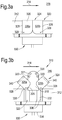
- the inspection device 318 is retractably mounted in the housing 320 so as to be movable between a stowed position (as shown in Figure 3a ) where the inspection device 312 is shielded from the environment of the cavity, and an inspection position (as shown in Figure 3b ) in which the inspection device 318 is exposed to the cavity so as to allow inspection.
- the engine 310 also includes a shutter 324 which provides an environmental shield for the inspection device 318 in the stowed position.
- the shutter 324 is arranged to be actuable between a closed configuration ( Figure 3a ) and an open configuration ( Figure 3b ).
- the shutter 324 is also retractably mounted within the housing 320 so as to have a stowed position which corresponds to the closed configuration, and an inspection position which corresponds to the open configuration.
- the shutter 324 includes a cup shaped shield 326 having an internal chamber which fits over and receives the inspection device 318 when in the stowed position.
- the cup shaped shield 326 is inverted within the housing aperture 322 such that a base 326 of the cup faces the gas flow path 314 with the side walls 328 being snugly received within the aperture 322 of the compressor wall 312 with the inspection device 318 located within the internal chamber of the shutter 324.
- the shutter 324 and housing 320 combine to provide an enclosed protective space for the inspection device 318, with the base of the shutter 324 shielding the inspection device 318 from the cavity 316.
- the shutter 324 is made from two shutter plates 326a, 326b which are similar to each other in construction and arranged in a symmetrically opposing manner so as to each provide half of the cup shaped shield 326 when in a closed configuration.
- Each shutter plate 326a, 326b is pivotably mounted 329 to an actuation mechanism 330 towards a distal end of the shutter 324 relative to the cavity such that, when they are not constrained by the housing 320, rotating the shutter plates 326a, 326b, about the pivot 329 results in each shutter plate 326a, 326b being moved away from the inspection device 318 to expose it to the cavity 316.
- shutter plates 326a, 326b are symmetrically arranged, they form a pincer or scissor-like arrangement such that the cup-like structure of the shutter 324 pivotably parts along a midline so as to reveal the inspection device 318.
- the shutter 324 can be thought of a shield to protect the inspection device 318 from the ambient operating environment which may be beyond the safe operating environment for the inspection device 318.
- the in use operating temperature may be several hundred degrees which would damage the inspection device 318.
- the shutter acts as a thermal shield and may be made from any suitable temperture resistant metal alloy or ceramic as known in the art.
- the inspection device 318 of the embodiment is a camera.
- the camera may be configured to detect infrared emitted within the compressor but it will be appreciated that other visual and non-visual inspection devices may be advantageously used depending on the application. Having an infrared camera is particularly advantageous as it allows the thermal condition of the engine to be analysed during, for example, a wind down period. This can provide an invaluable insight into the condition of the engine and allow detection of flaws in components.
- the camera is arranged to sense visible light and includes a wide angle lens 331 in the form of a 150 degree lens and a plurality of LEDs 333 to illuminate the interior of the cavity to be inspected.
- the inspection device is in the form of a light channelling medium or conduit such as fibre optic cable or light pipe which terminates at 331 as shown in Figure 3b , in view of the cavity.
- a fibre optic may include the aforementioned wide angle lens.
- the camera, or sensor which detects the light is located remote to the cavity.
- the end of the fibre optic 331 collects light from the cavity and channels them to the sensor which detects them.
- the sensor will have some associated electronics to process the signal of the sensed image which may or may not be local to the sensor. In this way, the shielding requirements may be much reduced as sensitive electronic components associated with the sensor and signal processing equipment need not be protected from the environment of the cavity to the same degree.
- the inspection device 318 is retractable between a stowed position and an inspection position in conjunction with the shutter plates 326a, 326b, ( Figures 3a and 3b respectively).
- An actuation mechanism 330 is included in the arrangement and is operable to move the inspection device 318 and shutter 324 between the stowed position and the inspection position.
- the actuation mechanism 330 of the described embodiment is a linear actuator 332 which is operable to retract and deploy the inspection device 318 and shutter 324 simultaneously.
- the actuation mechanism 330 includes driving mechanism 332 located within a actuation housing 334.
- the driving mechanism 332 is linked to the shutter 324 and inspection device 318 via push rods 326 which are operably extended in use after an appropriate driving signal is provided.
- the type of linear actuator and driving mechanism 332 may be hydraulic, pneumatic or electrical and it will be appreciated that non-linear, e.g. rotary, actuators may also be suitably applied.
- the actuation of the shutters 324 can be achieved in multiple ways.
- the shutter plates 326a, 326b are resiliently biased against a restraining element in the form of the walls of the housing aperture 322 such that pushing the shutter 324 into the cavity 316 results in the lateral movement and associated opening of the shutter plates 326a, 326b. Withdrawing the shutter 324 back into the recess causes the shutter plates 326a, 326b to contact the shoulder 338 of the housing aperture 322 which rotates the plates 326a, 326b about the pivot, thereby closing them.
- the inside surface of the shutter 324 which faces the inspection device 318 lens may include a cleaning device 340 which acts to clean the inspection device 318 upon opening of the shutter plates 326a, 326b and the associated lateral movement.
- the cleaning device 340 may be a cloth or bristled structure.
- the inspection device 318 arrangement may be inserted into the housing aperture 322 and secured by any known means.
- the inspection device 318 and shutter 324 are threadingly engaged within the compressor wall 320 such that they can be removed for maintenance purposes.
- the shutter 324, inspection device 318 and actuation mechanism 330 are constructed and presented to the engine 310 as a single module.
- an inspection device 318 behind a shutter 324 allows the inspection device 318 to be left in situ and used whenever the engine conditions allow.
- the inspection device 318 may be placed within a section of compressor and exposed to view the operation of the compressor during start up or close down periods when the temperature is not excessive, but while it is still hot enough to give off a useful thermal signature.
- Having an inspection device can provide important information about the operation of the engine and can aid engine health monitoring schemes. Arranging the device to be retractable is particularly advantageous as it allows a broader field of view to be accommodated.
- the actuator mechanism 330 is energised so as to push the device into the gas stream flow path 314 to allow the wide angle lens 331 to view the rotating components as they windmill down to stop. Once the rotation speed is low enough to enable a sufficient video capture rate, the rotations are recorded and logged directly to the EMU (Engine Monitoring Unit). Once the required capture is complete, the actuation mechanism 330 pulls the device back into the aperture 322 and the shutter is closed so as to seal off the gas path.
- EMU Engine Monitoring Unit
- the inspection device 318 arrangement also includes a means of removing the data captured by the camera.
- the inspection device 318 may be hard wired to the EMU or could be wirelessly connected.
- the trigger for energising the actuation mechanism 330 may be automatic or may be provided by an operator.
- the operator may be local to the engine, for example, a pilot or maintenance staff, or may be a remote monitor such as an engine health monitoring system.
- the invention is described primarily from a view point of being used on a compressor of a gas turbine engine 10, it will be appreciated that the invention may be implemented at various locations around such an engine.
- the invention may be utilised in the compressor, combustor, or any other area in which active inspection may be beneficial.
- the shutter 324 may include a single plate or an iris like structure. Further, the shutter may not be retractable with the inspection device but may be configured to move laterally with respect to the inspection device and housing aperture. Further still, the inspection device may be suitable type which may provide valuable data, such as a thermocouple, visible light spectrum, or pressure to name a few.
Landscapes
- Engineering & Computer Science (AREA)
- Chemical & Material Sciences (AREA)
- Mechanical Engineering (AREA)
- General Engineering & Computer Science (AREA)
- Combustion & Propulsion (AREA)
- Biochemistry (AREA)
- Life Sciences & Earth Sciences (AREA)
- Analytical Chemistry (AREA)
- Health & Medical Sciences (AREA)
- General Health & Medical Sciences (AREA)
- General Physics & Mathematics (AREA)
- Immunology (AREA)
- Pathology (AREA)
- Physics & Mathematics (AREA)
- Testing Of Engines (AREA)
- Investigating Materials By The Use Of Optical Means Adapted For Particular Applications (AREA)
Claims (14)
- Moteur à turbine à gaz (10) possédant une cavité (316) permettant une inspection, comprenant :
un dispositif d'inspection (318) monté dans un boîtier (320), ledit boîtier étant au moins partiellement situé adjacent à la cavité à inspecter et comportant un obturateur (324) pouvant être actionné entre une configuration fermée et une configuration ouverte ; et un mécanisme d'actionnement (330) destiné à déplacer l'obturateur entre la configuration fermée et la configuration ouverte, caractérisé en ce que :
le dispositif d'inspection est rétractable entre une position escamotée et une position d'inspection. - Moteur à turbine à gaz selon la revendication 1, ledit dispositif d'inspection étant conçu pour permettre une inspection visuelle de la cavité.
- Moteur à turbine à gaz selon l'une quelconque des revendications précédentes, ledit obturateur étant escamoté de façon rétractable dans le boîtier lorsqu'il est dans la configuration fermée et actionné dans la cavité de façon à exposer le dispositif d'inspection lorsqu'il est dans la configuration ouverte.
- Moteur à turbine à gaz selon l'une quelconque des revendications précédentes, ledit obturateur étant conçu pour être actionné par le dispositif d'inspection lorsque le dispositif d'inspection est déplacé entre la position escamotée et la position d'inspection.
- Moteur à turbine à gaz selon l'une quelconque des revendications précédentes, ledit obturateur comprenant un dispositif de nettoyage (340) destiné à nettoyer le dispositif d'inspection.
- Moteur à turbine à gaz selon l'une quelconque des revendications précédentes, ledit obturateur et ledit dispositif d'inspection pouvant être actionnés simultanément.
- Moteur à turbine à gaz selon l'une quelconque des revendications précédentes, ledit mécanisme d'actionnement étant l'un choisi dans le groupe comprenant un mécanisme d'actionnement pneumatique, hydraulique ou électrique.
- Moteur à turbine à gaz selon l'une quelconque des revendications précédentes, ledit boîtier étant au moins partiellement formé à l'intérieur d'une paroi (312) de la cavité.
- Moteur à turbine à gaz selon l'une quelconque des revendications précédentes, ladite cavité comprenant des parties mobiles du moteur à combustion interne.
- Moteur à turbine à gaz selon l'une quelconque des revendications précédentes, ledit obturateur comprenant un écran de protection (326) en forme de coupe, ledit écran de protection en forme de coupe possédant une chambre interne qui s'ajuste au-dessus du dispositif d'inspection et le reçoit, dans une position escamotée.
- Moteur à turbine à gaz selon l'une quelconque des revendications précédentes, ledit obturateur comprenant au moins une plaque d'obturateur qui est sollicitée contre un élément de retenue (338) de façon à retenir la plaque d'obturateur en place lorsqu'il est dans une configuration fermée et ledit actionnement de l'obturateur de la configuration fermée vers la configuration ouverte comprenant le déplacement des plaques d'obturateur par rapport à l'élément de retenue de sorte que la sollicitation entraîne l'exposition du dispositif d'inspection à la cavité.
- Moteur à turbine à gaz selon l'une quelconque des revendications précédentes, ledit obturateur comprenant des première et seconde plaques (326a, 326b).
- Aéronef possédant le moteur à turbine à gaz selon les revendications 1 à 12.
- Aéronef selon la revendication 13, ledit mécanisme d'actionnement pouvant être actionné depuis le poste de pilotage d'un aéronef ou en tant que partie d'un système de surveillance de la santé d'un moteur.
Applications Claiming Priority (1)
| Application Number | Priority Date | Filing Date | Title |
|---|---|---|---|
| GBGB1204913.6A GB201204913D0 (en) | 2012-03-21 | 2012-03-21 | An inspection device for an internal combustion engine |
Publications (3)
| Publication Number | Publication Date |
|---|---|
| EP2642085A2 EP2642085A2 (fr) | 2013-09-25 |
| EP2642085A3 EP2642085A3 (fr) | 2018-02-21 |
| EP2642085B1 true EP2642085B1 (fr) | 2019-05-08 |
Family
ID=46052261
Family Applications (1)
| Application Number | Title | Priority Date | Filing Date |
|---|---|---|---|
| EP13157988.0A Active EP2642085B1 (fr) | 2012-03-21 | 2013-03-06 | Dispositif d'inspection pour moteur à turbine à gas |
Country Status (3)
| Country | Link |
|---|---|
| US (1) | US9322332B2 (fr) |
| EP (1) | EP2642085B1 (fr) |
| GB (1) | GB201204913D0 (fr) |
Cited By (1)
| Publication number | Priority date | Publication date | Assignee | Title |
|---|---|---|---|---|
| EP4077886A1 (fr) * | 2019-12-18 | 2022-10-26 | MTU Aero Engines AG | Système de surveillance d'état avec dispositif d'endoscope industriel pour turbine à gaz |
Families Citing this family (6)
| Publication number | Priority date | Publication date | Assignee | Title |
|---|---|---|---|---|
| GB201609820D0 (en) * | 2016-06-06 | 2016-07-20 | Rolls Royce Plc | Condensation Irradiation system |
| GB2553144B (en) | 2016-08-26 | 2019-10-30 | Rolls Royce Plc | Apparatus for insertion into a cavity of an object |
| US10808534B2 (en) * | 2017-02-08 | 2020-10-20 | General Electric Company | Reconfigurable maintenance apparatus |
| US11103964B2 (en) | 2018-12-06 | 2021-08-31 | General Electric Company | Service apparatus for use with rotary machines |
| JP7595604B2 (ja) * | 2022-01-12 | 2024-12-06 | ニデックプレシジョン株式会社 | シャッター機構及び検査装置 |
| US12379645B2 (en) | 2023-04-18 | 2025-08-05 | Rtx Corporation | Propulsor blade imaging assembly for an aircraft propulsion system |
Family Cites Families (7)
| Publication number | Priority date | Publication date | Assignee | Title |
|---|---|---|---|---|
| US4787053A (en) * | 1981-12-30 | 1988-11-22 | Semco Instruments, Inc. | Comprehensive engine monitor and recorder |
| SU1321844A1 (ru) * | 1985-06-17 | 1987-07-07 | Харьковский Филиал Центрального Конструкторского Бюро Главэнергоремонта | Устройство дл осмотра проточной части двухкорпусного цилиндра турбомашины |
| US4666297A (en) * | 1985-11-14 | 1987-05-19 | United Technologies Corporation | Dual spectra optical pyrometer having an air pressure sensitive shutter |
| GB2244047B (en) | 1990-05-17 | 1994-02-16 | Rolls Royce Plc | Inspection aperture sealing |
| JP3487944B2 (ja) * | 1995-02-24 | 2004-01-19 | オリンパス株式会社 | 内視鏡装置 |
| US6091489A (en) * | 1998-02-25 | 2000-07-18 | Welker Engineering Company | Optical inspection apparatus for pressurized vessels |
| JP4468551B2 (ja) * | 2000-06-08 | 2010-05-26 | 川惣電機工業株式会社 | 燃焼炉における炉内測温装置 |
-
2012
- 2012-03-21 GB GBGB1204913.6A patent/GB201204913D0/en not_active Ceased
-
2013
- 2013-03-06 EP EP13157988.0A patent/EP2642085B1/fr active Active
- 2013-03-07 US US13/788,906 patent/US9322332B2/en active Active
Non-Patent Citations (1)
| Title |
|---|
| None * |
Cited By (1)
| Publication number | Priority date | Publication date | Assignee | Title |
|---|---|---|---|---|
| EP4077886A1 (fr) * | 2019-12-18 | 2022-10-26 | MTU Aero Engines AG | Système de surveillance d'état avec dispositif d'endoscope industriel pour turbine à gaz |
Also Published As
| Publication number | Publication date |
|---|---|
| EP2642085A3 (fr) | 2018-02-21 |
| US20130247540A1 (en) | 2013-09-26 |
| US9322332B2 (en) | 2016-04-26 |
| GB201204913D0 (en) | 2012-05-02 |
| EP2642085A2 (fr) | 2013-09-25 |
Similar Documents
| Publication | Publication Date | Title |
|---|---|---|
| EP2642085B1 (fr) | Dispositif d'inspection pour moteur à turbine à gas | |
| EP3179238B1 (fr) | Système et procédé permettant d'effectuer une inspection visuelle d'un moteur à turbine à gaz | |
| EP3287771B1 (fr) | Appareil d'insertion dans la cavité d'un objet | |
| US20060088793A1 (en) | Optical viewing system for monitoring a wide angle area of interest exposed to high temperature | |
| US11346239B2 (en) | Heat flux measurement system | |
| KR101540928B1 (ko) | 터빈 엔진 내의 관심부분의 영역을 모니터링하기 위한 시스템 | |
| US20090112519A1 (en) | Foreign object/domestic object damage assessment | |
| US8570505B2 (en) | One-dimensional coherent fiber array for inspecting components in a gas turbine engine | |
| EP4105451B1 (fr) | Ensemble capteur de turbine à gaz et mécanisme d'obturateur associé | |
| BR102016028830A2 (pt) | método e sistema para localizar sondas | |
| US20170234772A1 (en) | Optical imaging system for inspecting turbine engine components and method for operating same | |
| EP3399160A1 (fr) | Procede d'inspection d'un moteur de turbine a gaz | |
| JPS61500812A (ja) | ガスタ−ビンをコントロ−ルする光学式高温計透視管組立体 | |
| US10845253B2 (en) | Turbine thermal monitoring systems and methods | |
| US12379645B2 (en) | Propulsor blade imaging assembly for an aircraft propulsion system | |
| EP4450774A2 (fr) | Ensemble d'imagerie de pale de propulseur pour système de propulsion d'aéronef | |
| CN103968950A (zh) | 多色高温测定成像系统及其操作方法 | |
| GB2493770A (en) | Determining the position and orientation of a remote end of a boroscope | |
| EP4134643A1 (fr) | Système de mesure sans contact à haute température | |
| US20230132178A1 (en) | State monitoring system having a borescope device for a gas turbine | |
| EP4397591A1 (fr) | Ensemble de verrouillage pour capot de système de propulsion d'aéronef | |
| JP2004339944A (ja) | ガスタービンのモニタリング装置および方法 | |
| WO2025248125A1 (fr) | Systèmes d'inspection pour composants et procédés de turbine à gaz | |
| HK1027031A (en) | Topical drug preparations |
Legal Events
| Date | Code | Title | Description |
|---|---|---|---|
| PUAI | Public reference made under article 153(3) epc to a published international application that has entered the european phase |
Free format text: ORIGINAL CODE: 0009012 |
|
| AK | Designated contracting states |
Kind code of ref document: A2 Designated state(s): AL AT BE BG CH CY CZ DE DK EE ES FI FR GB GR HR HU IE IS IT LI LT LU LV MC MK MT NL NO PL PT RO RS SE SI SK SM TR |
|
| AX | Request for extension of the european patent |
Extension state: BA ME |
|
| RAP1 | Party data changed (applicant data changed or rights of an application transferred) |
Owner name: ROLLS-ROYCE PLC |
|
| PUAL | Search report despatched |
Free format text: ORIGINAL CODE: 0009013 |
|
| AK | Designated contracting states |
Kind code of ref document: A3 Designated state(s): AL AT BE BG CH CY CZ DE DK EE ES FI FR GB GR HR HU IE IS IT LI LT LU LV MC MK MT NL NO PL PT RO RS SE SI SK SM TR |
|
| AX | Request for extension of the european patent |
Extension state: BA ME |
|
| RIC1 | Information provided on ipc code assigned before grant |
Ipc: F01D 21/00 20060101AFI20180116BHEP Ipc: G01N 21/954 20060101ALI20180116BHEP |
|
| STAA | Information on the status of an ep patent application or granted ep patent |
Free format text: STATUS: REQUEST FOR EXAMINATION WAS MADE |
|
| 17P | Request for examination filed |
Effective date: 20180710 |
|
| RBV | Designated contracting states (corrected) |
Designated state(s): AL AT BE BG CH CY CZ DE DK EE ES FI FR GB GR HR HU IE IS IT LI LT LU LV MC MK MT NL NO PL PT RO RS SE SI SK SM TR |
|
| GRAP | Despatch of communication of intention to grant a patent |
Free format text: ORIGINAL CODE: EPIDOSNIGR1 |
|
| STAA | Information on the status of an ep patent application or granted ep patent |
Free format text: STATUS: GRANT OF PATENT IS INTENDED |
|
| GRAS | Grant fee paid |
Free format text: ORIGINAL CODE: EPIDOSNIGR3 |
|
| INTG | Intention to grant announced |
Effective date: 20190128 |
|
| GRAA | (expected) grant |
Free format text: ORIGINAL CODE: 0009210 |
|
| STAA | Information on the status of an ep patent application or granted ep patent |
Free format text: STATUS: THE PATENT HAS BEEN GRANTED |
|
| AK | Designated contracting states |
Kind code of ref document: B1 Designated state(s): AL AT BE BG CH CY CZ DE DK EE ES FI FR GB GR HR HU IE IS IT LI LT LU LV MC MK MT NL NO PL PT RO RS SE SI SK SM TR |
|
| REG | Reference to a national code |
Ref country code: GB Ref legal event code: FG4D |
|
| REG | Reference to a national code |
Ref country code: CH Ref legal event code: EP Ref country code: AT Ref legal event code: REF Ref document number: 1130422 Country of ref document: AT Kind code of ref document: T Effective date: 20190515 |
|
| REG | Reference to a national code |
Ref country code: DE Ref legal event code: R096 Ref document number: 602013054888 Country of ref document: DE Ref country code: IE Ref legal event code: FG4D |
|
| REG | Reference to a national code |
Ref country code: NL Ref legal event code: MP Effective date: 20190508 |
|
| REG | Reference to a national code |
Ref country code: LT Ref legal event code: MG4D |
|
| PG25 | Lapsed in a contracting state [announced via postgrant information from national office to epo] |
Ref country code: HR Free format text: LAPSE BECAUSE OF FAILURE TO SUBMIT A TRANSLATION OF THE DESCRIPTION OR TO PAY THE FEE WITHIN THE PRESCRIBED TIME-LIMIT Effective date: 20190508 Ref country code: SE Free format text: LAPSE BECAUSE OF FAILURE TO SUBMIT A TRANSLATION OF THE DESCRIPTION OR TO PAY THE FEE WITHIN THE PRESCRIBED TIME-LIMIT Effective date: 20190508 Ref country code: NO Free format text: LAPSE BECAUSE OF FAILURE TO SUBMIT A TRANSLATION OF THE DESCRIPTION OR TO PAY THE FEE WITHIN THE PRESCRIBED TIME-LIMIT Effective date: 20190808 Ref country code: PT Free format text: LAPSE BECAUSE OF FAILURE TO SUBMIT A TRANSLATION OF THE DESCRIPTION OR TO PAY THE FEE WITHIN THE PRESCRIBED TIME-LIMIT Effective date: 20190908 Ref country code: AL Free format text: LAPSE BECAUSE OF FAILURE TO SUBMIT A TRANSLATION OF THE DESCRIPTION OR TO PAY THE FEE WITHIN THE PRESCRIBED TIME-LIMIT Effective date: 20190508 Ref country code: FI Free format text: LAPSE BECAUSE OF FAILURE TO SUBMIT A TRANSLATION OF THE DESCRIPTION OR TO PAY THE FEE WITHIN THE PRESCRIBED TIME-LIMIT Effective date: 20190508 Ref country code: NL Free format text: LAPSE BECAUSE OF FAILURE TO SUBMIT A TRANSLATION OF THE DESCRIPTION OR TO PAY THE FEE WITHIN THE PRESCRIBED TIME-LIMIT Effective date: 20190508 Ref country code: ES Free format text: LAPSE BECAUSE OF FAILURE TO SUBMIT A TRANSLATION OF THE DESCRIPTION OR TO PAY THE FEE WITHIN THE PRESCRIBED TIME-LIMIT Effective date: 20190508 Ref country code: LT Free format text: LAPSE BECAUSE OF FAILURE TO SUBMIT A TRANSLATION OF THE DESCRIPTION OR TO PAY THE FEE WITHIN THE PRESCRIBED TIME-LIMIT Effective date: 20190508 |
|
| PG25 | Lapsed in a contracting state [announced via postgrant information from national office to epo] |
Ref country code: BG Free format text: LAPSE BECAUSE OF FAILURE TO SUBMIT A TRANSLATION OF THE DESCRIPTION OR TO PAY THE FEE WITHIN THE PRESCRIBED TIME-LIMIT Effective date: 20190808 Ref country code: RS Free format text: LAPSE BECAUSE OF FAILURE TO SUBMIT A TRANSLATION OF THE DESCRIPTION OR TO PAY THE FEE WITHIN THE PRESCRIBED TIME-LIMIT Effective date: 20190508 Ref country code: GR Free format text: LAPSE BECAUSE OF FAILURE TO SUBMIT A TRANSLATION OF THE DESCRIPTION OR TO PAY THE FEE WITHIN THE PRESCRIBED TIME-LIMIT Effective date: 20190809 Ref country code: LV Free format text: LAPSE BECAUSE OF FAILURE TO SUBMIT A TRANSLATION OF THE DESCRIPTION OR TO PAY THE FEE WITHIN THE PRESCRIBED TIME-LIMIT Effective date: 20190508 |
|
| REG | Reference to a national code |
Ref country code: AT Ref legal event code: MK05 Ref document number: 1130422 Country of ref document: AT Kind code of ref document: T Effective date: 20190508 |
|
| PG25 | Lapsed in a contracting state [announced via postgrant information from national office to epo] |
Ref country code: RO Free format text: LAPSE BECAUSE OF FAILURE TO SUBMIT A TRANSLATION OF THE DESCRIPTION OR TO PAY THE FEE WITHIN THE PRESCRIBED TIME-LIMIT Effective date: 20190508 Ref country code: DK Free format text: LAPSE BECAUSE OF FAILURE TO SUBMIT A TRANSLATION OF THE DESCRIPTION OR TO PAY THE FEE WITHIN THE PRESCRIBED TIME-LIMIT Effective date: 20190508 Ref country code: AT Free format text: LAPSE BECAUSE OF FAILURE TO SUBMIT A TRANSLATION OF THE DESCRIPTION OR TO PAY THE FEE WITHIN THE PRESCRIBED TIME-LIMIT Effective date: 20190508 Ref country code: EE Free format text: LAPSE BECAUSE OF FAILURE TO SUBMIT A TRANSLATION OF THE DESCRIPTION OR TO PAY THE FEE WITHIN THE PRESCRIBED TIME-LIMIT Effective date: 20190508 Ref country code: CZ Free format text: LAPSE BECAUSE OF FAILURE TO SUBMIT A TRANSLATION OF THE DESCRIPTION OR TO PAY THE FEE WITHIN THE PRESCRIBED TIME-LIMIT Effective date: 20190508 Ref country code: SK Free format text: LAPSE BECAUSE OF FAILURE TO SUBMIT A TRANSLATION OF THE DESCRIPTION OR TO PAY THE FEE WITHIN THE PRESCRIBED TIME-LIMIT Effective date: 20190508 |
|
| REG | Reference to a national code |
Ref country code: DE Ref legal event code: R097 Ref document number: 602013054888 Country of ref document: DE |
|
| RAP2 | Party data changed (patent owner data changed or rights of a patent transferred) |
Owner name: ROLLS-ROYCE PLC |
|
| PG25 | Lapsed in a contracting state [announced via postgrant information from national office to epo] |
Ref country code: SM Free format text: LAPSE BECAUSE OF FAILURE TO SUBMIT A TRANSLATION OF THE DESCRIPTION OR TO PAY THE FEE WITHIN THE PRESCRIBED TIME-LIMIT Effective date: 20190508 Ref country code: IT Free format text: LAPSE BECAUSE OF FAILURE TO SUBMIT A TRANSLATION OF THE DESCRIPTION OR TO PAY THE FEE WITHIN THE PRESCRIBED TIME-LIMIT Effective date: 20190508 |
|
| PLBE | No opposition filed within time limit |
Free format text: ORIGINAL CODE: 0009261 |
|
| STAA | Information on the status of an ep patent application or granted ep patent |
Free format text: STATUS: NO OPPOSITION FILED WITHIN TIME LIMIT |
|
| PG25 | Lapsed in a contracting state [announced via postgrant information from national office to epo] |
Ref country code: TR Free format text: LAPSE BECAUSE OF FAILURE TO SUBMIT A TRANSLATION OF THE DESCRIPTION OR TO PAY THE FEE WITHIN THE PRESCRIBED TIME-LIMIT Effective date: 20190508 |
|
| 26N | No opposition filed |
Effective date: 20200211 |
|
| PG25 | Lapsed in a contracting state [announced via postgrant information from national office to epo] |
Ref country code: PL Free format text: LAPSE BECAUSE OF FAILURE TO SUBMIT A TRANSLATION OF THE DESCRIPTION OR TO PAY THE FEE WITHIN THE PRESCRIBED TIME-LIMIT Effective date: 20190508 |
|
| PG25 | Lapsed in a contracting state [announced via postgrant information from national office to epo] |
Ref country code: SI Free format text: LAPSE BECAUSE OF FAILURE TO SUBMIT A TRANSLATION OF THE DESCRIPTION OR TO PAY THE FEE WITHIN THE PRESCRIBED TIME-LIMIT Effective date: 20190508 |
|
| PG25 | Lapsed in a contracting state [announced via postgrant information from national office to epo] |
Ref country code: MC Free format text: LAPSE BECAUSE OF FAILURE TO SUBMIT A TRANSLATION OF THE DESCRIPTION OR TO PAY THE FEE WITHIN THE PRESCRIBED TIME-LIMIT Effective date: 20190508 |
|
| REG | Reference to a national code |
Ref country code: CH Ref legal event code: PL |
|
| REG | Reference to a national code |
Ref country code: BE Ref legal event code: MM Effective date: 20200331 |
|
| PG25 | Lapsed in a contracting state [announced via postgrant information from national office to epo] |
Ref country code: LU Free format text: LAPSE BECAUSE OF NON-PAYMENT OF DUE FEES Effective date: 20200306 |
|
| PG25 | Lapsed in a contracting state [announced via postgrant information from national office to epo] |
Ref country code: CH Free format text: LAPSE BECAUSE OF NON-PAYMENT OF DUE FEES Effective date: 20200331 Ref country code: LI Free format text: LAPSE BECAUSE OF NON-PAYMENT OF DUE FEES Effective date: 20200331 Ref country code: IE Free format text: LAPSE BECAUSE OF NON-PAYMENT OF DUE FEES Effective date: 20200306 |
|
| PG25 | Lapsed in a contracting state [announced via postgrant information from national office to epo] |
Ref country code: BE Free format text: LAPSE BECAUSE OF NON-PAYMENT OF DUE FEES Effective date: 20200331 |
|
| PG25 | Lapsed in a contracting state [announced via postgrant information from national office to epo] |
Ref country code: MT Free format text: LAPSE BECAUSE OF FAILURE TO SUBMIT A TRANSLATION OF THE DESCRIPTION OR TO PAY THE FEE WITHIN THE PRESCRIBED TIME-LIMIT Effective date: 20190508 Ref country code: CY Free format text: LAPSE BECAUSE OF FAILURE TO SUBMIT A TRANSLATION OF THE DESCRIPTION OR TO PAY THE FEE WITHIN THE PRESCRIBED TIME-LIMIT Effective date: 20190508 |
|
| PG25 | Lapsed in a contracting state [announced via postgrant information from national office to epo] |
Ref country code: MK Free format text: LAPSE BECAUSE OF FAILURE TO SUBMIT A TRANSLATION OF THE DESCRIPTION OR TO PAY THE FEE WITHIN THE PRESCRIBED TIME-LIMIT Effective date: 20190508 Ref country code: IS Free format text: LAPSE BECAUSE OF FAILURE TO SUBMIT A TRANSLATION OF THE DESCRIPTION OR TO PAY THE FEE WITHIN THE PRESCRIBED TIME-LIMIT Effective date: 20190908 |
|
| P01 | Opt-out of the competence of the unified patent court (upc) registered |
Effective date: 20230528 |
|
| PGFP | Annual fee paid to national office [announced via postgrant information from national office to epo] |
Ref country code: GB Payment date: 20260323 Year of fee payment: 14 |
|
| PGFP | Annual fee paid to national office [announced via postgrant information from national office to epo] |
Ref country code: DE Payment date: 20260320 Year of fee payment: 14 |
|
| PGFP | Annual fee paid to national office [announced via postgrant information from national office to epo] |
Ref country code: FR Payment date: 20260323 Year of fee payment: 14 |