EP3287771B1 - Appareil d'insertion dans la cavité d'un objet - Google Patents
Appareil d'insertion dans la cavité d'un objet Download PDFInfo
- Publication number
- EP3287771B1 EP3287771B1 EP17183445.0A EP17183445A EP3287771B1 EP 3287771 B1 EP3287771 B1 EP 3287771B1 EP 17183445 A EP17183445 A EP 17183445A EP 3287771 B1 EP3287771 B1 EP 3287771B1
- Authority
- EP
- European Patent Office
- Prior art keywords
- tube
- cavity
- aperture
- gas turbine
- turbine engine
- Prior art date
- Legal status (The legal status is an assumption and is not a legal conclusion. Google has not performed a legal analysis and makes no representation as to the accuracy of the status listed.)
- Active
Links
Images





Classifications
-
- B—PERFORMING OPERATIONS; TRANSPORTING
- B23—MACHINE TOOLS; METAL-WORKING NOT OTHERWISE PROVIDED FOR
- B23P—METAL-WORKING NOT OTHERWISE PROVIDED FOR; COMBINED OPERATIONS; UNIVERSAL MACHINE TOOLS
- B23P6/00—Restoring or reconditioning objects
-
- F—MECHANICAL ENGINEERING; LIGHTING; HEATING; WEAPONS; BLASTING
- F01—MACHINES OR ENGINES IN GENERAL; ENGINE PLANTS IN GENERAL; STEAM ENGINES
- F01D—NON-POSITIVE DISPLACEMENT MACHINES OR ENGINES, e.g. STEAM TURBINES
- F01D21/00—Shutting-down of machines or engines, e.g. in emergency; Regulating, controlling, or safety means not otherwise provided for
- F01D21/003—Arrangements for testing or measuring
-
- F—MECHANICAL ENGINEERING; LIGHTING; HEATING; WEAPONS; BLASTING
- F01—MACHINES OR ENGINES IN GENERAL; ENGINE PLANTS IN GENERAL; STEAM ENGINES
- F01D—NON-POSITIVE DISPLACEMENT MACHINES OR ENGINES, e.g. STEAM TURBINES
- F01D11/00—Preventing or minimising internal leakage of working-fluid, e.g. between stages
- F01D11/003—Preventing or minimising internal leakage of working-fluid, e.g. between stages by packing rings; Mechanical seals
-
- F—MECHANICAL ENGINEERING; LIGHTING; HEATING; WEAPONS; BLASTING
- F01—MACHINES OR ENGINES IN GENERAL; ENGINE PLANTS IN GENERAL; STEAM ENGINES
- F01D—NON-POSITIVE DISPLACEMENT MACHINES OR ENGINES, e.g. STEAM TURBINES
- F01D25/00—Component parts, details, or accessories, not provided for in, or of interest apart from, other groups
- F01D25/24—Casings; Casing parts, e.g. diaphragms, casing fastenings
-
- F—MECHANICAL ENGINEERING; LIGHTING; HEATING; WEAPONS; BLASTING
- F01—MACHINES OR ENGINES IN GENERAL; ENGINE PLANTS IN GENERAL; STEAM ENGINES
- F01D—NON-POSITIVE DISPLACEMENT MACHINES OR ENGINES, e.g. STEAM TURBINES
- F01D5/00—Blades; Blade-carrying members; Heating, heat-insulating, cooling or antivibration means on the blades or the members
- F01D5/005—Repairing methods or devices
-
- G—PHYSICS
- G01—MEASURING; TESTING
- G01M—TESTING STATIC OR DYNAMIC BALANCE OF MACHINES OR STRUCTURES; TESTING OF STRUCTURES OR APPARATUS, NOT OTHERWISE PROVIDED FOR
- G01M15/00—Testing of engines
- G01M15/14—Testing gas-turbine engines or jet-propulsion engines
-
- G—PHYSICS
- G01—MEASURING; TESTING
- G01N—INVESTIGATING OR ANALYSING MATERIALS BY DETERMINING THEIR CHEMICAL OR PHYSICAL PROPERTIES
- G01N21/00—Investigating or analysing materials by the use of optical means, i.e. using sub-millimetre waves, infrared, visible or ultraviolet light
- G01N21/84—Systems specially adapted for particular applications
- G01N21/88—Investigating the presence of flaws or contamination
- G01N21/95—Investigating the presence of flaws or contamination characterised by the material or shape of the object to be examined
- G01N21/954—Inspecting the inner surface of hollow bodies, e.g. bores
-
- G—PHYSICS
- G02—OPTICS
- G02B—OPTICAL ELEMENTS, SYSTEMS OR APPARATUS
- G02B23/00—Telescopes, e.g. binoculars; Periscopes; Instruments for viewing the inside of hollow bodies; Viewfinders; Optical aiming or sighting devices
- G02B23/24—Instruments or systems for viewing the inside of hollow bodies, e.g. fibrescopes
- G02B23/2476—Non-optical details, e.g. housings, mountings, supports
-
- G—PHYSICS
- G02—OPTICS
- G02B—OPTICAL ELEMENTS, SYSTEMS OR APPARATUS
- G02B23/00—Telescopes, e.g. binoculars; Periscopes; Instruments for viewing the inside of hollow bodies; Viewfinders; Optical aiming or sighting devices
- G02B23/24—Instruments or systems for viewing the inside of hollow bodies, e.g. fibrescopes
- G02B23/26—Instruments or systems for viewing the inside of hollow bodies, e.g. fibrescopes using light guides
-
- F—MECHANICAL ENGINEERING; LIGHTING; HEATING; WEAPONS; BLASTING
- F05—INDEXING SCHEMES RELATING TO ENGINES OR PUMPS IN VARIOUS SUBCLASSES OF CLASSES F01-F04
- F05D—INDEXING SCHEME FOR ASPECTS RELATING TO NON-POSITIVE-DISPLACEMENT MACHINES OR ENGINES, GAS-TURBINES OR JET-PROPULSION PLANTS
- F05D2220/00—Application
- F05D2220/30—Application in turbines
- F05D2220/32—Application in turbines in gas turbines
-
- F—MECHANICAL ENGINEERING; LIGHTING; HEATING; WEAPONS; BLASTING
- F05—INDEXING SCHEMES RELATING TO ENGINES OR PUMPS IN VARIOUS SUBCLASSES OF CLASSES F01-F04
- F05D—INDEXING SCHEME FOR ASPECTS RELATING TO NON-POSITIVE-DISPLACEMENT MACHINES OR ENGINES, GAS-TURBINES OR JET-PROPULSION PLANTS
- F05D2260/00—Function
- F05D2260/83—Testing, e.g. methods, components or tools therefor
-
- F—MECHANICAL ENGINEERING; LIGHTING; HEATING; WEAPONS; BLASTING
- F05—INDEXING SCHEMES RELATING TO ENGINES OR PUMPS IN VARIOUS SUBCLASSES OF CLASSES F01-F04
- F05D—INDEXING SCHEME FOR ASPECTS RELATING TO NON-POSITIVE-DISPLACEMENT MACHINES OR ENGINES, GAS-TURBINES OR JET-PROPULSION PLANTS
- F05D2270/00—Control
- F05D2270/80—Devices generating input signals, e.g. transducers, sensors, cameras or strain gauges
- F05D2270/804—Optical devices
- F05D2270/8041—Cameras
-
- G—PHYSICS
- G01—MEASURING; TESTING
- G01N—INVESTIGATING OR ANALYSING MATERIALS BY DETERMINING THEIR CHEMICAL OR PHYSICAL PROPERTIES
- G01N21/00—Investigating or analysing materials by the use of optical means, i.e. using sub-millimetre waves, infrared, visible or ultraviolet light
- G01N21/84—Systems specially adapted for particular applications
- G01N21/85—Investigating moving fluids or granular solids
- G01N21/8507—Probe photometers, i.e. with optical measuring part dipped into fluid sample
Definitions
- the present disclosure concerns apparatus for insertion into a cavity of an object.
- Gas turbine engines may sustain wear and/or damage during operation that may reduce the efficiency of the gas turbine engine. Inspection and repair of a gas turbine engine may be a relatively time consuming task and may require disassembly of the gas turbine engine. For example, gas turbine engines used in aviation are usually mounted on a wing of an aircraft. Inspection and repair of such a gas turbine engine may require the gas turbine engine to be removed from the wing of the aircraft and then disassembled to allow access to the worn and/or damaged component.
- US6091489 relates to an optic device for use in viewing the interior of pressurized vessels, especially high pressure fluid pipelines.
- the optic device allows manual or automatic insertion/retraction of the viewing head allowing variable depth viewing of the interior.
- the viewing head is capable of various embodiments including the ability to carry various optic devices and is adapted to withstand high pressures.
- the automatically insertable optic device can be either hydraulically or pneumatically actuated.
- Both the automatic and manual optic devices may be fixed or variable focus.
- the fixed focus devices utilize lenses, ultra-miniature colour cameras, and fiberscopes either with or without integral light sources as part of the viewing head.
- the variable focus device utilizes lenses and a reflector.
- the viewing head may utilize sapphire viewing windows which enable light transmission and resistance to high pressures. In this manner, light may be received for pickup by the lenses, camera, fiberscope, or the like.
- US2014/063227 relates to optical camera systems for non-destructive internal inspection of online, operating power generation turbines, including gas turbine combustor and turbine sections that are at high operating temperatures in the range of over 600 degrees centigrade (1112 degrees Fahrenheit) and which include combustion gas contaminants.
- the inspection system includes one or more aspheric lenses capable of withstanding continuous operating temperatures above 600 degrees centigrade.
- the aspheric lenses alone or in combination with spherical lenses, establish a wider field of view, and require fewer lenses in combination than lens mounts incorporating only spherical lenses.
- a cooling system incorporated in the inspection system facilitates continuous operation and inhibits lens external surface fouling from combustion gasses.
- apparatus for insertion into a cavity of an object, the apparatus comprising: a first tube comprising a first end, a second end, a first cavity extending between the first end and the second end, and an aperture; a plug coupled to the second end of the first tube; and an actuator configured to move the first tube relative to the object between a first position in which the plug seals the aperture from the cavity of the object, and a second position in which the aperture is exposed to the cavity of the object.
- the apparatus may further comprise a second tube including a first end, a second end, and a second cavity extending between the first end and the second end.
- the first tube may be positioned within the second cavity of the second tube.
- the actuator may be configured to move the first tube relative to the second tube.
- the plug may form a seal with the second end of the second tube when the first tube is at the first position.
- the aperture of the first tube may be positioned external to the second tube when the first tube is at the second position.
- the apparatus may further comprise a connector arrangement configured to connect the apparatus to the object.
- the connector arrangement may be configured to enable an operator to connect the apparatus to the object.
- the connector arrangement may be configured to enable an operator to disconnect and remove the apparatus from the object.
- the first tube may be hollow and may have another aperture at the first end of the first tube.
- the apparatus may be configured to function as a valve to control a flow of fluid to or from the cavity of the object.
- the apparatus may further comprise a member positioned within the first cavity of the first tube and adjacent the aperture of the first tube.
- the member may be configured to enable an action to be performed.
- the member may comprise one or more optical fibres.
- the apparatus may further comprise an optical sensor coupled to the one or more optical fibres,
- the optical sensor may be positioned external to the first tube.
- the member may comprise an optical sensor, and the optical sensor may be positioned internal to the first tube.
- the optical sensor may be positioned adjacent the aperture of the first tube.
- the member may comprise repair apparatus for performing a repair on the object.
- the member may comprise non-destructive examination (NDE) apparatus.
- NDE non-destructive examination
- the aperture may be located at the second end of the first tube.
- the object may be a gas turbine engine.
- the cavity may be a gas path of the gas turbine engine.
- a system comprising: a gas turbine engine including a first inspection port; and an apparatus as described in any of the preceding paragraphs extending inside the first inspection port.
- the gas turbine engine may further comprise a second inspection port, and the system may further comprise another apparatus as described in any of the preceding paragraphs extending inside the second inspection port.
- Fig. 1 illustrates a schematic side view of apparatus 10 and an object 12 according to various examples.
- the apparatus 10 includes a first tube 14, a plug 16 and an actuator 18.
- the object 12 may be any article, module, component, part, or assembly of components that define a cavity 20 and an opening 22 to the cavity 20.
- the object 12 may be a gas turbine engine or a module of a gas turbine engine.
- the object 12 may be an internal combustion engine for a vehicle.
- the object 12 may be a pipeline, a storage tank, or other container.
- the opening 22 may be a borescope port and the cavity 20 may be a gas path within the gas turbine engine.
- the apparatus 10 may be inserted into the cavity 20 of the object 12 via the opening 22 to enable an inspection, a repair activity, or a non-destructive examination to be performed.
- the apparatus 10 may be inserted into the cavity 20 of the object 12 via the opening 22 to function as a valve.
- the first tube 14 extends along a longitudinal axis 27 and includes a first end 24 a second opposite end 26.
- the first tube 14 may have any suitable cross sectional shape and may have, for example, a circular, elliptical, or a polygonal cross sectional shape.
- the first tube 14 also includes a first cavity 28 that extends between the first end 24 and the second end 26 along the longitudinal axis 27. In some examples, the first cavity 28 extends from the first end 24 to the second end 26 and the first end 24 and the second end 26 may be open. In other examples, the first cavity 28 has a length along the longitudinal axis 27 that is less than the length of the first tube 14 along the longitudinal axis 27 and consequently, the first end 24 and/or the second end 26 may be closed.
- the first tube 14 also includes an aperture 30 that provides an opening to the cavity 28.
- the aperture 30 may have any suitable shape and may be circular, elliptical or have a polygonal shape for example.
- the aperture 30 may be located at the second end 26 of the first tube 14 as illustrated in Fig. 1 . In other examples, the aperture 30 may be located at any position between the first end 24 and the second end 26.
- the aperture 30 may be an open aperture or may be covered by a material that is transparent to electromagnetic waves within one or more portions of the electromagnetic spectrum. For example, the aperture 30 may be covered by glass that is transparent to light.
- the plug 16 is coupled to the second end 26 of the first tube 14.
- the plug 16 may be coupled to the second end 26 via an adhesive.
- the plug 16 may be welded to the first tube 14.
- the plug 16 may be integral with the first tube 14 and may define the second end 26 of the first tube 14.
- the plug 16 may be sized and shaped to plug the opening 22 of the object 12 and thereby seal the cavity 20.
- the plug 16 may be sized and shaped to plug the borescope port and thereby seal the gas path within the gas turbine engine.
- the actuator 18 may include any suitable device for moving the first tube 14 relative to the object 12.
- the actuator 18 may include a servomotor, a hydraulic cylinder, a pneumatic cylinder, a rack and pinion, a cam rotatable on a shaft, or a lead screw.
- the actuator 18 is configured to move the first tube 14 relative to the object 12 and parallel to the longitudinal axis 27 as indicated by arrow 32.
- the actuator 18 is configured to move the first tube 14 between a first position in which the plug 16 seals the aperture 30 from the cavity 20 of the object 12, and a second position in which the aperture 30 is exposed to the cavity 20 of the object 12 (as illustrated in Fig. 1 ).
- the apparatus 10 may receive a member in the first cavity 28 for enabling one or more actions to be performed, and this is described in greater detail in the following paragraphs with reference to Figs. 2 and 4 .
- the first cavity 28 of the first tube 14 may be hollow and where the first end 24 of the first tube 14 is open (that is, the first tube 14 has another aperture at the first end 24), the apparatus 10 may be configured to function as a valve to control a flow of fluid to or from the cavity 20 of the object 12.
- fluid within the cavity 20 may ingress the first tube 14 at the aperture 30 and then egress the first tube 14 at the open first end 24.
- fluid outside of the cavity 20 may ingress the first tube 14 at the open first end 24 and then egress the first tube 14 at the aperture 30 into the cavity 20 of the object 12.
- Figs. 2A and 2B illustrate a schematic side view of another apparatus 101 and an object 12.
- the apparatus 101 and the object 12 are similar to the apparatus 10 and the object 12 illustrated in Fig. 1 respectively, and where the features are similar, the same reference numerals are used.
- the apparatus 101 differs from the apparatus 10 in that the apparatus 101 further comprises a member 34 positioned within the first cavity 28 of the first tube 14 and adjacent the aperture 30 of the first tube 14.
- the member 34 may completely cover the aperture 30 (and may or may not seal the aperture 30). In other examples, the member 34 may only partially cover the aperture 30.
- Fig. 2A illustrates the first tube 14 in the second position in which the aperture 30 is exposed to the cavity 20 of the object 12.
- Fig. 2B illustrates the first tube 14 in the first position in which the plug 16 seals the aperture 30 from the cavity 20 of the object 12.
- the member 34 is configured to enable one or more actions to be performed.
- the actions may include (but are not limited to) an inspection activity, and/or a repair activity, and/or a machining activity.
- the member 34 may comprise inspection apparatus for enabling the interior of the object 12 to be inspected by a human operator and/or a computer.
- the member 34 may comprise one or more optical fibres to enable electromagnetic waves to be transmitted from the aperture 30 and/or to enable electromagnetic waves to be received via the aperture 30.
- the apparatus 101 may further comprise an optical sensor (such as a charge coupled device (CCD) camera, or a complementary metal oxide semiconductor (CMOS) camera) coupled to the one or more optical fibres.
- the optical sensor may be positioned external to the first tube 14 or may be positioned internal to the first tube 14.
- the apparatus 101 may comprise a device for emitting electromagnetic waves (such as a laser, a light emitting diode, a halogen bulb for example) that is coupled to the one or more optical fibres.
- the device for emitting electromagnetic waves may be positioned external to the first tube 14 or may be positioned internal to the first tube 14.
- the member 34 may comprise repair apparatus for performing a repair on the object 12.
- the apparatus 34 may comprise one or more optical fibres and a laser as described in the preceding paragraph to enable the apparatus 10 to clean the object 12 or to drill the object 12.
- the member 34 may comprise one or more nozzles for spraying a coating on the object 12.
- the member 34 may comprise one or more nozzles and a pump for extracting fluid from the cavity 20 of the object 12 (for example, to create a vacuum in the cavity 20).
- the member 34 may comprise a machine tool such as a milling tool or a drill.
- the member 34 may comprise non-destructive examination (NDE) apparatus (which may also be referred to as non-destructive testing (NDT) apparatus).
- NDE non-destructive examination
- the member 34 may comprise one or more optical fibres, a sensor (as described above) and a computer for enabling non-destructive examination to be performed.
- the member 34 may comprise an ultrasonic transducer and a computer for enabling non-destructive examination to be performed.
- the member 34 may comprise infrared and thermal testing apparatus for enabling non-destructive examination to be performed. It should be appreciated that the member 34 may comprise any suitable non-destructive examination apparatus and is not limited to the examples provided above.
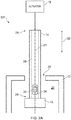
- Figs. 3A and 3B illustrate a schematic side view of a further apparatus 102 and an object 12 according to various examples.
- the apparatus 102 and the object 12 are similar to the apparatus 10 and the object 12 respectively, and where the features are similar, the same reference numerals are used.
- the apparatus 102 differs from the apparatus 10 in that the apparatus 102 further comprises a second tube 36 including a first end 38 and a second opposite end 40.
- the second tube 36 is T shaped when viewed from the side (as illustrated in Fig. 3A ) and consequently includes a first part (at the first end 38) that extends perpendicular to the longitudinal axis 27, and a second part that extends parallel to the longitudinal axis 27.
- the second tube 36 may have any suitable cross sectional shape and may have a circular cross sectional shape, an elliptical cross sectional shape or a polygonal cross sectional shape.
- the second tube 36 defines a second cavity 42 that extends between the first end 38 and the second end 40 of the second tube 36. As illustrated in Fig. 3A , the first end 38 and the second end 40 are open.
- the first tube 14 is positioned within the second cavity 42 of the second tube 36.
- the first tube 14 and the second tube 36 are arranged concentrically and share the longitudinal axis 27. In other examples, the first tube 14 and the second tube 36 are not arranged concentrically and consequently have separate longitudinal axes.
- the object 12 includes a first wall 121 and a second wall 122 (which may be casing walls of a gas turbine engine for example).
- the first end 38 of the second tube 36 extends through an opening 46 in the first wall 121 and the second end 40 of the second tube 36 extends through an opening 22 in the second wall 122.
- the apparatus 102 includes a connector arrangement 44 that is configured to connect the apparatus 102 to the object 12.
- the connector arrangement 44 comprises a plurality of fasteners 48 (such as screws or bolts) that extend through the first end 38 of the second tube 36 and into the first wall 121.
- the connector arrangement 44 may include an alternative mechanism for connecting the apparatus 102 to the object 12 and may include an adhesive for example. Consequently, the second tube 36 may be fixed to the first wall 121 and be static relative to the first wall 121.
- the actuator 18 is configured to move the first tube 14 relative to the second tube 36 and relative to the object 12 between a first position and a second position.
- the aperture 30 is positioned within the cavity 42 of the second tube 36 and the plug 16 forms a seal with the second end 40 of the second tube 36. Consequently, the aperture 30 is sealed from the cavity 20 of the object 12 by the plug 16 and the second end 40 of the second tube 36.
- the plug 16 When the first tube 14 is located at the second position (as illustrated in Fig. 3A ), the plug 16 is positioned remote from the second end 40 of the second tube 36 and the aperture 30 of the first tube 14 is positioned external to the second tube 36. Consequently, the aperture 30 is exposed to the cavity 20 and the first tube 14 extends further into the cavity 20 than when the first tube 14 is at the first position.
- the apparatus 102 may receive a member for enabling an action to be performed and this is described in greater detail in the following paragraphs with reference to Fig. 4 .
- the apparatus 102 may function as a valve as described above with reference to Fig. 1 .
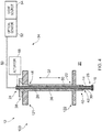
- Fig. 4 illustrates a schematic side view of another apparatus 103 and an object 12 according to various examples.
- the apparatus 103 is similar to the apparatus 102 and where the features are similar, the same reference numerals are used.
- the apparatus 103 differs from the apparatus 102 in that the apparatus 103 further comprises a member 34 including a plurality of optical fibres 50, an optical sensor 52 and a light source 54.
- the plurality of optical fibres 50 have a first end positioned at the aperture 30 of the first tube 14, and a second end connected to the optical sensor 52 and the light source 54.
- the optical sensor 52 and the light source 54 are positioned externally of the first tube 14 and consequently, the plurality of optical fibres 50 include a first part that extends along the length of the first tube 14 within the first cavity 28 between the aperture 30 and the first end 24 of the first tube 14, and a second part that extends from the first end 24 of the first tube 14 to the optical sensor 52 and the light source 54.
- the optical sensor 52 may be any suitable optical sensor 52 and may be a charge coupled device (CCD) camera or a complementary metal oxide semiconductor (CMOS) camera for example. While the optical sensor 52 is illustrated as being positioned external to the first tube 14 in Fig. 4 , it should be appreciated that in other examples, the optical sensor 52 may be positioned within the first cavity 28 of the first tube 14. For example, the optical sensor 52 may be positioned at the aperture 30 of the first tube 14.
- CCD charge coupled device
- CMOS complementary metal oxide semiconductor
- the light source 54 may be any suitable emitter of visible light and may comprise a light emitting diode or a laser. In some examples, the light source 54 may be configured to emit infrared radiation or ultraviolet radiation. While the light source 54 is illustrated as being positioned external to the first tube 14 in Fig. 4 , it should be appreciated that in other examples, the light source 54 may be positioned within the first cavity 28 of the first tube 14.
- the light source 54 is configured to emit light which is conveyed to the aperture 30 of the first tube 14 via the plurality of optical fibres 50.
- the plurality of optical fibres 50 direct the light out of the aperture 30 and into the cavity 20 of the object 12. The light is then reflected by the surfaces of the object 12 and some of the reflected light is received at the aperture 30 which is conveyed to the optical sensor 52 via the plurality of optical fibres 50.
- the apparatus 10, 101, 102, 103 may provide several advantages.
- the apparatus 10, 102 may function as a valve for enabling fluid to be removed from, or provided to, the cavity 20 of the object 12.
- the apparatus 101, 103 (which includes the member 34) enables an action (such as inspection, repair, non-destructive examination) to be performed within the cavity 20 of the object 12.
- the plug 16 may provide an effective seal with the object 12 (as illustrated in Figs. 1 and 2 ) or with the second tube 36 and may consequently protect the member 34 from being damaged by fluids within the cavity 20 of the object 12.
- the plug 16 may be sized and dimensioned to fit snugly inside the opening 22 of the object 12 and consequently, the object 12 may not require modification to be used with the apparatus 10, 101, 102, 103.
- the plug 16 may not comprise any movable mechanical parts and consequently, the plug 16 may be relatively simple and may be less likely to fail during operation.
- the remote positioning of a sensor from the first tube 14 may provide more space for the sensor and thereby allow the sensor to have a larger sensor area with a higher resolution.
- Fig. 5 illustrates a schematic cross sectional side view of a system 56 comprising: a gas turbine engine 110 including a first inspection port 22; and an apparatus 10, 101, 102, 103 as described in the preceding paragraphs extending inside the first inspection port 22.
- the gas turbine engine 110 (or a module of the gas turbine engine 110) may be considered to be the object 12 described in the preceding paragraphs.
- the gas turbine engine 110 has a principal and rotational axis 111 (which may be perpendicular to the longitudinal axis 27 of the apparatus 10, 101, 102, 103).
- the gas turbine engine 110 comprises, in axial flow series, an air intake 112, a propulsive fan 113, an intermediate pressure compressor 114, a high-pressure compressor 115, combustion equipment 116, a high-pressure turbine 117, an intermediate pressure turbine 118, a low-pressure turbine 119 and an exhaust nozzle 120.
- a nacelle 121 generally surrounds the engine 110 and defines both the intake 112 and the exhaust nozzle 120.
- the gas turbine engine 110 operates so that air entering the intake 112 is accelerated by the fan 113 to produce two air flows: a first air flow into the intermediate pressure compressor 114 and a second air flow which passes through a bypass duct 122 to provide propulsive thrust.
- the intermediate pressure compressor 114 compresses the air flow directed into it before delivering that air to the high pressure compressor 115 where further compression takes place.
- the compressed air exhausted from the high-pressure compressor 115 is directed into the combustion equipment 116 where it is mixed with fuel and the mixture combusted.
- the resultant hot combustion products then expand through, and thereby drive the high, intermediate and low-pressure turbines 117, 118, 119 before being exhausted through the nozzle 120 to provide additional propulsive thrust.
- the high 117, intermediate 118 and low 119 pressure turbines drive respectively the high pressure compressor 115, intermediate pressure compressor 114 and fan 113, each by suitable interconnecting shaft.
- gas turbine engines to which the present disclosure may be applied may have alternative configurations.
- such engines may have an alternative number of interconnecting shafts (e.g. two) and/or an alternative number of compressors and/or turbines.
- the gas turbine engine may comprise a gearbox provided in the drive train from a turbine to a compressor and/or fan.
- the first inspection port 22 is a borescope port through the casing of the intermediate pressure compressor 114 and the cavity 20 is the gas path within the intermediate pressure compressor 114.
- the gas turbine engine 110 may further comprise a second inspection port 58 (for example, another borescope port through the casing of the intermediate pressure compressor 114), and the system 56 further comprises another apparatus 10, 101, 102, 103 as described in the preceding paragraphs extending inside the second inspection port 58.
- Part of the member 34 may be mounted to (or embedded within) the external surface of the casing of the intermediate pressure compressor 114. This may advantageously enable components that may be damaged by high temperatures (such as the optical sensor 52) to be positioned remote from the gas path 20 and in a region that experiences lower operating temperatures.
- first tube 14 (and the second tube 36 in the examples illustrated in Figs. 2 and 4 ) may not be straight and may instead be curved.
- the first tube 14 may not be hollow (that is, the first tube 14 may not define the first cavity 38 and may be solid), and the member 34 may be coupled to the exterior surface of the first tube 14.
Landscapes
- Physics & Mathematics (AREA)
- Engineering & Computer Science (AREA)
- General Physics & Mathematics (AREA)
- Mechanical Engineering (AREA)
- General Engineering & Computer Science (AREA)
- Astronomy & Astrophysics (AREA)
- Optics & Photonics (AREA)
- Chemical & Material Sciences (AREA)
- Combustion & Propulsion (AREA)
- Health & Medical Sciences (AREA)
- Life Sciences & Earth Sciences (AREA)
- Analytical Chemistry (AREA)
- Biochemistry (AREA)
- General Health & Medical Sciences (AREA)
- Immunology (AREA)
- Pathology (AREA)
- Investigating Materials By The Use Of Optical Means Adapted For Particular Applications (AREA)
Claims (14)
- Appareil (10, 101, 102, 103) destiné à être inséré dans une cavité (20) d'un objet (12), l'appareil comprenant :
un premier tube (14) comprenant une première extrémité (24), une seconde extrémité (26), une première cavité (28) s'étendant entre la première extrémité (24) et la seconde extrémité (26), et une ouverture (30) caractérisée par un bouchon (16) couplé à la seconde extrémité (26) du premier tube (14) ; et un actionneur (18) conçu pour déplacer le premier tube (14) par rapport à l'objet (12) entre une première position dans laquelle le bouchon (16) scelle l'ouverture (30) de la cavité (20) de l'objet (12), et une seconde position dans laquelle l'ouverture (30) est exposée à la cavité (20) de l'objet (12). - Appareil selon la revendication 1, comprenant en outre un second tube (36) comprenant une première extrémité (38), une seconde extrémité (40) et une seconde cavité (42) s'étendant entre la première extrémité (38) et la seconde extrémité (40), le premier tube (14) étant positionné à l'intérieur de la seconde cavité (42) du second tube (36), l'actionneur (18) étant conçu pour déplacer le premier tube (14) par rapport au second tube (36).
- Appareil selon la revendication 2, ledit bouchon (16) formant un joint d'étanchéité avec la seconde extrémité (40) du second tube (36) lorsque le premier tube (14) est au niveau de la première position, et ladite ouverture (30) du premier tube (14) étant positionné à l'extérieur du second tube (36) lorsque le premier tube (14) est au niveau de la seconde position.
- Appareil selon l'une quelconque des revendications précédentes, comprenant en outre un agencement de connecteur (44) conçu pour raccorder l'appareil à l'objet.
- Appareil selon la revendication 4, ledit agencement de connecteur (44) étant conçu pour permettre à un opérateur de raccorder l'appareil à l'objet, et pour permettre à un opérateur de séparer et de retirer l'appareil de l'objet.
- Appareil selon l'une quelconque des revendications précédentes, ledit premier tube (14) étant creux et possédant une autre ouverture au niveau de la première extrémité (24) du premier tube (14), ledit appareil étant conçu pour fonctionner en tant que soupape pour commander un écoulement de fluide vers la cavité de l'objet ou en provenance de celle-ci.
- Appareil selon l'une quelconque des revendications 1 à 5, comprenant en outre un élément (34) positionné à l'intérieur de la première cavité (28) du premier tube (14) et adjacent à l'ouverture (30) du premier tube (14), l'élément (34) étant conçu pour permettre la réalisation d'une action.
- Appareil selon la revendication 7, ledit élément (34) comprenant une ou plusieurs fibres optiques (50), et ledit appareil comprenant en outre un capteur optique (52) couplé à la ou aux fibres optiques (50).
- Appareil selon la revendication 8, ledit capteur optique (52) étant positionné à l'extérieur du premier tube.
- Appareil selon la revendications 7, ledit élément (34) comprenant un capteur optique, ou ledit élément comprenant un appareil de réparation destiné à effectuer une réparation sur l'objet, ou ledit élément comprenant un appareil d'examen non destructif, NDE.
- Appareil selon l'une quelconque des revendications précédentes, ladite ouverture (30) étant située au niveau de la seconde extrémité (26) du premier tube (14).
- Appareil selon l'une quelconque des revendications précédentes, ledit objet étant un moteur à turbine à gaz (110), et ladite cavité étant un trajet de gaz du moteur à turbine à gaz.
- Système (56) comprenant : un moteur à turbine à gaz (110) comprenant un premier orifice d'inspection (22) ; et un appareil (10, 101, 102, 103) selon l'une quelconque des revendications précédentes s'étendant à l'intérieur du premier orifice d'inspection (22).
- Système (56) selon la revendication 13, ledit moteur à turbine à gaz (110) comprenant en outre un second orifice d'inspection (58), et ledit système (56) comprenant en outre un autre appareil (10, 101, 102, 103) selon la revendication selon l'une quelconque des revendications 1 à 12 s'étendant à l'intérieur du second orifice d'inspection (58).
Applications Claiming Priority (1)
| Application Number | Priority Date | Filing Date | Title |
|---|---|---|---|
| GB1614554.2A GB2553144B (en) | 2016-08-26 | 2016-08-26 | Apparatus for insertion into a cavity of an object |
Publications (2)
| Publication Number | Publication Date |
|---|---|
| EP3287771A1 EP3287771A1 (fr) | 2018-02-28 |
| EP3287771B1 true EP3287771B1 (fr) | 2021-03-17 |
Family
ID=57119901
Family Applications (1)
| Application Number | Title | Priority Date | Filing Date |
|---|---|---|---|
| EP17183445.0A Active EP3287771B1 (fr) | 2016-08-26 | 2017-07-27 | Appareil d'insertion dans la cavité d'un objet |
Country Status (4)
| Country | Link |
|---|---|
| US (1) | US10633993B2 (fr) |
| EP (1) | EP3287771B1 (fr) |
| GB (1) | GB2553144B (fr) |
| SG (1) | SG10201706240PA (fr) |
Families Citing this family (19)
| Publication number | Priority date | Publication date | Assignee | Title |
|---|---|---|---|---|
| GB2553144B (en) * | 2016-08-26 | 2019-10-30 | Rolls Royce Plc | Apparatus for insertion into a cavity of an object |
| GB201615429D0 (en) * | 2016-09-12 | 2016-10-26 | Rolls Royce Plc | Apparatus for insertion into a cavity of an object |
| US12194620B2 (en) | 2018-10-15 | 2025-01-14 | Oliver Crisipin Robotics Limited | Selectively flexible extension tool |
| US11707819B2 (en) | 2018-10-15 | 2023-07-25 | General Electric Company | Selectively flexible extension tool |
| US11702955B2 (en) | 2019-01-14 | 2023-07-18 | General Electric Company | Component repair system and method |
| US10996140B2 (en) * | 2019-03-08 | 2021-05-04 | Rolls-Royce Corporation | Gas turbine engine probes and methods of detecting an engine condition |
| US11260477B2 (en) | 2019-05-02 | 2022-03-01 | MTU Aero Engines AG | Repair tool for turbomachinery and related method |
| CN112610291A (zh) * | 2019-10-04 | 2021-04-06 | 通用电气公司 | 用于结合旋转机器使用的插入设备 |
| US12405187B2 (en) | 2019-10-04 | 2025-09-02 | General Electric Company | Insertion apparatus for use with rotary machines |
| US11752622B2 (en) | 2020-01-23 | 2023-09-12 | General Electric Company | Extension tool having a plurality of links |
| US11692650B2 (en) | 2020-01-23 | 2023-07-04 | General Electric Company | Selectively flexible extension tool |
| US11613003B2 (en) | 2020-01-24 | 2023-03-28 | General Electric Company | Line assembly for an extension tool having a plurality of links |
| US11371437B2 (en) | 2020-03-10 | 2022-06-28 | Oliver Crispin Robotics Limited | Insertion tool |
| US12091981B2 (en) | 2020-06-11 | 2024-09-17 | General Electric Company | Insertion tool and method |
| US12416800B2 (en) | 2021-01-08 | 2025-09-16 | General Electric Company | Insertion tool |
| US12504616B2 (en) | 2021-01-08 | 2025-12-23 | General Electric Company | Insertion tool |
| US11654547B2 (en) | 2021-03-31 | 2023-05-23 | General Electric Company | Extension tool |
| JP7124985B1 (ja) * | 2022-01-31 | 2022-08-24 | トヨタ自動車株式会社 | 射出装置、及び異物除去方法 |
| GB202207505D0 (en) | 2022-05-23 | 2022-07-06 | Rolls Royce Plc | System for use with component of power generation apparatus |
Family Cites Families (33)
| Publication number | Priority date | Publication date | Assignee | Title |
|---|---|---|---|---|
| DE2515753A1 (de) * | 1975-04-10 | 1976-10-14 | Siemens Ag | Waermerohr |
| US4300774A (en) | 1980-04-28 | 1981-11-17 | General Electric Company | Removable sealing plug for spaced apart wall structure |
| US4461343A (en) * | 1982-01-28 | 1984-07-24 | Mcdonnell Douglas Corporation | Plated heat pipe |
| CA1277230C (fr) * | 1988-12-01 | 1990-12-04 | Roderick D. Mcleod | Outil d'isolement pour tete de forage |
| US5317607A (en) * | 1993-04-30 | 1994-05-31 | Combustion Engineering, Inc. | EDM crack removal tooling |
| FR2708072B1 (fr) | 1993-07-21 | 1995-09-01 | Snecma | Bouchon amovible de trois trous ménagés dans des parois à températures différentes. |
| JP3487944B2 (ja) * | 1995-02-24 | 2004-01-19 | オリンパス株式会社 | 内視鏡装置 |
| US6091489A (en) * | 1998-02-25 | 2000-07-18 | Welker Engineering Company | Optical inspection apparatus for pressurized vessels |
| US6749395B1 (en) * | 1999-07-29 | 2004-06-15 | Siemens Aktiengesellschaft | Device and method for controlling a cooling air flow of a gas turbine |
| US6233937B1 (en) * | 2000-09-20 | 2001-05-22 | Siemens Westinghouse Power Corporation | Cooling spray application to a turbine and exhaust region of a steam turbine |
| WO2006007721A1 (fr) * | 2004-07-21 | 2006-01-26 | Xiao Huang | Materiaux a effet meche hybrides conçus pour etre utilises dans des caloducs haut rendement |
| JP4476116B2 (ja) * | 2004-12-27 | 2010-06-09 | 三菱重工業株式会社 | ガスタービン |
| CN100582638C (zh) * | 2006-04-14 | 2010-01-20 | 富准精密工业(深圳)有限公司 | 热管 |
| CN100498186C (zh) * | 2006-06-02 | 2009-06-10 | 富准精密工业(深圳)有限公司 | 热管 |
| US8015788B2 (en) * | 2006-12-27 | 2011-09-13 | General Electric Company | Heat transfer system for turbine engine using heat pipes |
| US8366609B2 (en) * | 2007-09-18 | 2013-02-05 | Olympus Medical Systems Corp. | Actuator and image pickup apparatus |
| US8397516B2 (en) * | 2009-10-01 | 2013-03-19 | General Electric Company | Apparatus and method for removing heat from a gas turbine |
| JP5714836B2 (ja) * | 2010-04-17 | 2015-05-07 | モレックス インコーポレイテドMolex Incorporated | 熱輸送ユニット、電子基板、電子機器 |
| FR2972053B1 (fr) * | 2011-02-28 | 2014-02-21 | Tokendo | Procede et dispositif d'inspection endoscopique par ressuage |
| US20120227925A1 (en) * | 2011-03-08 | 2012-09-13 | Daniel Sweeney | Thermal energy storage system with heat energy recovery sub-system |
| US20130168052A1 (en) * | 2011-12-30 | 2013-07-04 | Celsia Technologies Taiwan, Inc. | Heat pipe and composition of capillary wick thereof |
| US9217852B2 (en) * | 2012-01-31 | 2015-12-22 | Siemens Energy, Inc. | System and method for online inspection of turbines using an optical tube with broadspectrum mirrors |
| GB201204913D0 (en) | 2012-03-21 | 2012-05-02 | Rolls Royce Plc | An inspection device for an internal combustion engine |
| US9494052B2 (en) | 2012-03-27 | 2016-11-15 | United Technologies Corporation | Dual-intent locator pin and removable plug for gas turbines |
| US9028206B2 (en) * | 2012-06-12 | 2015-05-12 | General Electric Company | Thermally actuated assembly for a gas turbine system and method of controlling a cooling airflow path |
| US20140034848A1 (en) * | 2012-08-03 | 2014-02-06 | Brian Campbell | Photon turbine generator for power generation |
| CA2891549A1 (fr) * | 2012-11-30 | 2014-08-28 | General Electric Company | Ensemble moteur de turbine et systeme d'aeronef a double combustible |
| JP6218484B2 (ja) * | 2013-08-01 | 2017-10-25 | オリンパス株式会社 | 内視鏡検査用固定具 |
| JP6180221B2 (ja) * | 2013-08-01 | 2017-08-16 | オリンパス株式会社 | ブレード検査装置 |
| US9797310B2 (en) * | 2015-04-02 | 2017-10-24 | General Electric Company | Heat pipe temperature management system for a turbomachine |
| US9909448B2 (en) * | 2015-04-15 | 2018-03-06 | General Electric Company | Gas turbine engine component with integrated heat pipe |
| US10694641B2 (en) * | 2016-04-29 | 2020-06-23 | Intel Corporation | Wickless capillary driven constrained vapor bubble heat pipes for application in electronic devices with various system platforms |
| GB2553144B (en) * | 2016-08-26 | 2019-10-30 | Rolls Royce Plc | Apparatus for insertion into a cavity of an object |
-
2016
- 2016-08-26 GB GB1614554.2A patent/GB2553144B/en active Active
-
2017
- 2017-07-27 EP EP17183445.0A patent/EP3287771B1/fr active Active
- 2017-08-01 SG SG10201706240PA patent/SG10201706240PA/en unknown
- 2017-08-10 US US15/673,926 patent/US10633993B2/en active Active
Non-Patent Citations (1)
| Title |
|---|
| None * |
Also Published As
| Publication number | Publication date |
|---|---|
| US20180058233A1 (en) | 2018-03-01 |
| US10633993B2 (en) | 2020-04-28 |
| GB2553144B (en) | 2019-10-30 |
| GB201614554D0 (en) | 2016-10-12 |
| SG10201706240PA (en) | 2018-03-28 |
| GB2553144A (en) | 2018-02-28 |
| EP3287771A1 (fr) | 2018-02-28 |
Similar Documents
| Publication | Publication Date | Title |
|---|---|---|
| EP3287771B1 (fr) | Appareil d'insertion dans la cavité d'un objet | |
| CN107203036B (zh) | 用于燃气涡轮发动机的光学成像系统 | |
| US20190277770A1 (en) | Probe Insertion System | |
| US10473528B2 (en) | Optical apparatus and sight tube for inspecting turbine engine components | |
| EP3179237B1 (fr) | Système et procédé de commande d'une turbine à gaz | |
| US10940938B2 (en) | Pitch-changing system equipped with means for lubricating a load-transfer bearing | |
| US20170234772A1 (en) | Optical imaging system for inspecting turbine engine components and method for operating same | |
| US10060830B2 (en) | In-situ system and method of determining coating integrity of turbomachinery components | |
| US9322332B2 (en) | Inspection device for an internal combustion engine | |
| US20170218762A1 (en) | Situ Gas Turbine Prevention of Crack Growth Progression | |
| EP3293514B1 (fr) | Appareil d'insertion dans la cavité d'un objet | |
| US10094221B2 (en) | In situ gas turbine prevention of crack growth progression | |
| US10876426B2 (en) | Removable turbine gaspath sensor | |
| EP3203018A2 (fr) | Procédé pour arrêter une fissure dans un composant d'un moteur de turbine à gaz | |
| US20160238480A1 (en) | Seal vacuum check tool | |
| FR3041990A1 (fr) | Ensemble de propulsion d'un aeronef | |
| US20180066544A1 (en) | Gas shielding arrangements for gas turbine engines | |
| US20190316458A1 (en) | Insertion tool for inspection of vessel | |
| RU35658U1 (ru) | Турбина |
Legal Events
| Date | Code | Title | Description |
|---|---|---|---|
| PUAI | Public reference made under article 153(3) epc to a published international application that has entered the european phase |
Free format text: ORIGINAL CODE: 0009012 |
|
| STAA | Information on the status of an ep patent application or granted ep patent |
Free format text: STATUS: THE APPLICATION HAS BEEN PUBLISHED |
|
| AK | Designated contracting states |
Kind code of ref document: A1 Designated state(s): AL AT BE BG CH CY CZ DE DK EE ES FI FR GB GR HR HU IE IS IT LI LT LU LV MC MK MT NL NO PL PT RO RS SE SI SK SM TR |
|
| AX | Request for extension of the european patent |
Extension state: BA ME |
|
| STAA | Information on the status of an ep patent application or granted ep patent |
Free format text: STATUS: REQUEST FOR EXAMINATION WAS MADE |
|
| 17P | Request for examination filed |
Effective date: 20180820 |
|
| RBV | Designated contracting states (corrected) |
Designated state(s): AL AT BE BG CH CY CZ DE DK EE ES FI FR GB GR HR HU IE IS IT LI LT LU LV MC MK MT NL NO PL PT RO RS SE SI SK SM TR |
|
| RAP1 | Party data changed (applicant data changed or rights of an application transferred) |
Owner name: ROLLS-ROYCE PLC |
|
| RIC1 | Information provided on ipc code assigned before grant |
Ipc: G01M 15/14 20060101ALI20200713BHEP Ipc: G01N 21/954 20060101AFI20200713BHEP Ipc: G01N 21/85 20060101ALI20200713BHEP Ipc: G02B 23/26 20060101ALI20200713BHEP Ipc: G02B 23/24 20060101ALI20200713BHEP Ipc: F01D 25/24 20060101ALI20200713BHEP Ipc: F01D 21/00 20060101ALI20200713BHEP |
|
| GRAP | Despatch of communication of intention to grant a patent |
Free format text: ORIGINAL CODE: EPIDOSNIGR1 |
|
| STAA | Information on the status of an ep patent application or granted ep patent |
Free format text: STATUS: GRANT OF PATENT IS INTENDED |
|
| GRAJ | Information related to disapproval of communication of intention to grant by the applicant or resumption of examination proceedings by the epo deleted |
Free format text: ORIGINAL CODE: EPIDOSDIGR1 |
|
| STAA | Information on the status of an ep patent application or granted ep patent |
Free format text: STATUS: REQUEST FOR EXAMINATION WAS MADE |
|
| INTG | Intention to grant announced |
Effective date: 20201022 |
|
| INTC | Intention to grant announced (deleted) | ||
| GRAP | Despatch of communication of intention to grant a patent |
Free format text: ORIGINAL CODE: EPIDOSNIGR1 |
|
| STAA | Information on the status of an ep patent application or granted ep patent |
Free format text: STATUS: GRANT OF PATENT IS INTENDED |
|
| INTG | Intention to grant announced |
Effective date: 20210114 |
|
| GRAS | Grant fee paid |
Free format text: ORIGINAL CODE: EPIDOSNIGR3 |
|
| GRAA | (expected) grant |
Free format text: ORIGINAL CODE: 0009210 |
|
| STAA | Information on the status of an ep patent application or granted ep patent |
Free format text: STATUS: THE PATENT HAS BEEN GRANTED |
|
| AK | Designated contracting states |
Kind code of ref document: B1 Designated state(s): AL AT BE BG CH CY CZ DE DK EE ES FI FR GB GR HR HU IE IS IT LI LT LU LV MC MK MT NL NO PL PT RO RS SE SI SK SM TR |
|
| REG | Reference to a national code |
Ref country code: GB Ref legal event code: FG4D |
|
| REG | Reference to a national code |
Ref country code: CH Ref legal event code: EP |
|
| REG | Reference to a national code |
Ref country code: DE Ref legal event code: R096 Ref document number: 602017034634 Country of ref document: DE |
|
| REG | Reference to a national code |
Ref country code: IE Ref legal event code: FG4D |
|
| REG | Reference to a national code |
Ref country code: AT Ref legal event code: REF Ref document number: 1372693 Country of ref document: AT Kind code of ref document: T Effective date: 20210415 |
|
| REG | Reference to a national code |
Ref country code: LT Ref legal event code: MG9D |
|
| PG25 | Lapsed in a contracting state [announced via postgrant information from national office to epo] |
Ref country code: HR Free format text: LAPSE BECAUSE OF FAILURE TO SUBMIT A TRANSLATION OF THE DESCRIPTION OR TO PAY THE FEE WITHIN THE PRESCRIBED TIME-LIMIT Effective date: 20210317 Ref country code: FI Free format text: LAPSE BECAUSE OF FAILURE TO SUBMIT A TRANSLATION OF THE DESCRIPTION OR TO PAY THE FEE WITHIN THE PRESCRIBED TIME-LIMIT Effective date: 20210317 Ref country code: GR Free format text: LAPSE BECAUSE OF FAILURE TO SUBMIT A TRANSLATION OF THE DESCRIPTION OR TO PAY THE FEE WITHIN THE PRESCRIBED TIME-LIMIT Effective date: 20210618 Ref country code: NO Free format text: LAPSE BECAUSE OF FAILURE TO SUBMIT A TRANSLATION OF THE DESCRIPTION OR TO PAY THE FEE WITHIN THE PRESCRIBED TIME-LIMIT Effective date: 20210617 Ref country code: BG Free format text: LAPSE BECAUSE OF FAILURE TO SUBMIT A TRANSLATION OF THE DESCRIPTION OR TO PAY THE FEE WITHIN THE PRESCRIBED TIME-LIMIT Effective date: 20210617 |
|
| REG | Reference to a national code |
Ref country code: AT Ref legal event code: MK05 Ref document number: 1372693 Country of ref document: AT Kind code of ref document: T Effective date: 20210317 |
|
| REG | Reference to a national code |
Ref country code: NL Ref legal event code: MP Effective date: 20210317 |
|
| PG25 | Lapsed in a contracting state [announced via postgrant information from national office to epo] |
Ref country code: SE Free format text: LAPSE BECAUSE OF FAILURE TO SUBMIT A TRANSLATION OF THE DESCRIPTION OR TO PAY THE FEE WITHIN THE PRESCRIBED TIME-LIMIT Effective date: 20210317 Ref country code: LV Free format text: LAPSE BECAUSE OF FAILURE TO SUBMIT A TRANSLATION OF THE DESCRIPTION OR TO PAY THE FEE WITHIN THE PRESCRIBED TIME-LIMIT Effective date: 20210317 Ref country code: RS Free format text: LAPSE BECAUSE OF FAILURE TO SUBMIT A TRANSLATION OF THE DESCRIPTION OR TO PAY THE FEE WITHIN THE PRESCRIBED TIME-LIMIT Effective date: 20210317 |
|
| PG25 | Lapsed in a contracting state [announced via postgrant information from national office to epo] |
Ref country code: NL Free format text: LAPSE BECAUSE OF FAILURE TO SUBMIT A TRANSLATION OF THE DESCRIPTION OR TO PAY THE FEE WITHIN THE PRESCRIBED TIME-LIMIT Effective date: 20210317 |
|
| PG25 | Lapsed in a contracting state [announced via postgrant information from national office to epo] |
Ref country code: AT Free format text: LAPSE BECAUSE OF FAILURE TO SUBMIT A TRANSLATION OF THE DESCRIPTION OR TO PAY THE FEE WITHIN THE PRESCRIBED TIME-LIMIT Effective date: 20210317 Ref country code: SM Free format text: LAPSE BECAUSE OF FAILURE TO SUBMIT A TRANSLATION OF THE DESCRIPTION OR TO PAY THE FEE WITHIN THE PRESCRIBED TIME-LIMIT Effective date: 20210317 Ref country code: CZ Free format text: LAPSE BECAUSE OF FAILURE TO SUBMIT A TRANSLATION OF THE DESCRIPTION OR TO PAY THE FEE WITHIN THE PRESCRIBED TIME-LIMIT Effective date: 20210317 Ref country code: EE Free format text: LAPSE BECAUSE OF FAILURE TO SUBMIT A TRANSLATION OF THE DESCRIPTION OR TO PAY THE FEE WITHIN THE PRESCRIBED TIME-LIMIT Effective date: 20210317 Ref country code: LT Free format text: LAPSE BECAUSE OF FAILURE TO SUBMIT A TRANSLATION OF THE DESCRIPTION OR TO PAY THE FEE WITHIN THE PRESCRIBED TIME-LIMIT Effective date: 20210317 |
|
| PG25 | Lapsed in a contracting state [announced via postgrant information from national office to epo] |
Ref country code: PL Free format text: LAPSE BECAUSE OF FAILURE TO SUBMIT A TRANSLATION OF THE DESCRIPTION OR TO PAY THE FEE WITHIN THE PRESCRIBED TIME-LIMIT Effective date: 20210317 Ref country code: PT Free format text: LAPSE BECAUSE OF FAILURE TO SUBMIT A TRANSLATION OF THE DESCRIPTION OR TO PAY THE FEE WITHIN THE PRESCRIBED TIME-LIMIT Effective date: 20210719 Ref country code: RO Free format text: LAPSE BECAUSE OF FAILURE TO SUBMIT A TRANSLATION OF THE DESCRIPTION OR TO PAY THE FEE WITHIN THE PRESCRIBED TIME-LIMIT Effective date: 20210317 Ref country code: SK Free format text: LAPSE BECAUSE OF FAILURE TO SUBMIT A TRANSLATION OF THE DESCRIPTION OR TO PAY THE FEE WITHIN THE PRESCRIBED TIME-LIMIT Effective date: 20210317 Ref country code: IS Free format text: LAPSE BECAUSE OF FAILURE TO SUBMIT A TRANSLATION OF THE DESCRIPTION OR TO PAY THE FEE WITHIN THE PRESCRIBED TIME-LIMIT Effective date: 20210717 |
|
| REG | Reference to a national code |
Ref country code: DE Ref legal event code: R097 Ref document number: 602017034634 Country of ref document: DE |
|
| PLBE | No opposition filed within time limit |
Free format text: ORIGINAL CODE: 0009261 |
|
| STAA | Information on the status of an ep patent application or granted ep patent |
Free format text: STATUS: NO OPPOSITION FILED WITHIN TIME LIMIT |
|
| PG25 | Lapsed in a contracting state [announced via postgrant information from national office to epo] |
Ref country code: ES Free format text: LAPSE BECAUSE OF FAILURE TO SUBMIT A TRANSLATION OF THE DESCRIPTION OR TO PAY THE FEE WITHIN THE PRESCRIBED TIME-LIMIT Effective date: 20210317 Ref country code: AL Free format text: LAPSE BECAUSE OF FAILURE TO SUBMIT A TRANSLATION OF THE DESCRIPTION OR TO PAY THE FEE WITHIN THE PRESCRIBED TIME-LIMIT Effective date: 20210317 Ref country code: DK Free format text: LAPSE BECAUSE OF FAILURE TO SUBMIT A TRANSLATION OF THE DESCRIPTION OR TO PAY THE FEE WITHIN THE PRESCRIBED TIME-LIMIT Effective date: 20210317 |
|
| 26N | No opposition filed |
Effective date: 20211220 |
|
| PG25 | Lapsed in a contracting state [announced via postgrant information from national office to epo] |
Ref country code: SI Free format text: LAPSE BECAUSE OF FAILURE TO SUBMIT A TRANSLATION OF THE DESCRIPTION OR TO PAY THE FEE WITHIN THE PRESCRIBED TIME-LIMIT Effective date: 20210317 |
|
| REG | Reference to a national code |
Ref country code: CH Ref legal event code: PL |
|
| PG25 | Lapsed in a contracting state [announced via postgrant information from national office to epo] |
Ref country code: MC Free format text: LAPSE BECAUSE OF FAILURE TO SUBMIT A TRANSLATION OF THE DESCRIPTION OR TO PAY THE FEE WITHIN THE PRESCRIBED TIME-LIMIT Effective date: 20210317 |
|
| REG | Reference to a national code |
Ref country code: BE Ref legal event code: MM Effective date: 20210731 |
|
| PG25 | Lapsed in a contracting state [announced via postgrant information from national office to epo] |
Ref country code: LI Free format text: LAPSE BECAUSE OF NON-PAYMENT OF DUE FEES Effective date: 20210731 Ref country code: IT Free format text: LAPSE BECAUSE OF FAILURE TO SUBMIT A TRANSLATION OF THE DESCRIPTION OR TO PAY THE FEE WITHIN THE PRESCRIBED TIME-LIMIT Effective date: 20210317 Ref country code: CH Free format text: LAPSE BECAUSE OF NON-PAYMENT OF DUE FEES Effective date: 20210731 |
|
| PG25 | Lapsed in a contracting state [announced via postgrant information from national office to epo] |
Ref country code: IS Free format text: LAPSE BECAUSE OF FAILURE TO SUBMIT A TRANSLATION OF THE DESCRIPTION OR TO PAY THE FEE WITHIN THE PRESCRIBED TIME-LIMIT Effective date: 20210717 Ref country code: LU Free format text: LAPSE BECAUSE OF NON-PAYMENT OF DUE FEES Effective date: 20210727 |
|
| PG25 | Lapsed in a contracting state [announced via postgrant information from national office to epo] |
Ref country code: IE Free format text: LAPSE BECAUSE OF NON-PAYMENT OF DUE FEES Effective date: 20210727 Ref country code: BE Free format text: LAPSE BECAUSE OF NON-PAYMENT OF DUE FEES Effective date: 20210731 |
|
| PG25 | Lapsed in a contracting state [announced via postgrant information from national office to epo] |
Ref country code: HU Free format text: LAPSE BECAUSE OF FAILURE TO SUBMIT A TRANSLATION OF THE DESCRIPTION OR TO PAY THE FEE WITHIN THE PRESCRIBED TIME-LIMIT; INVALID AB INITIO Effective date: 20170727 |
|
| PG25 | Lapsed in a contracting state [announced via postgrant information from national office to epo] |
Ref country code: CY Free format text: LAPSE BECAUSE OF FAILURE TO SUBMIT A TRANSLATION OF THE DESCRIPTION OR TO PAY THE FEE WITHIN THE PRESCRIBED TIME-LIMIT Effective date: 20210317 |
|
| P01 | Opt-out of the competence of the unified patent court (upc) registered |
Effective date: 20230528 |
|
| PG25 | Lapsed in a contracting state [announced via postgrant information from national office to epo] |
Ref country code: MK Free format text: LAPSE BECAUSE OF FAILURE TO SUBMIT A TRANSLATION OF THE DESCRIPTION OR TO PAY THE FEE WITHIN THE PRESCRIBED TIME-LIMIT Effective date: 20210317 |
|
| PG25 | Lapsed in a contracting state [announced via postgrant information from national office to epo] |
Ref country code: MT Free format text: LAPSE BECAUSE OF FAILURE TO SUBMIT A TRANSLATION OF THE DESCRIPTION OR TO PAY THE FEE WITHIN THE PRESCRIBED TIME-LIMIT Effective date: 20210317 |
|
| PGFP | Annual fee paid to national office [announced via postgrant information from national office to epo] |
Ref country code: DE Payment date: 20250728 Year of fee payment: 9 |
|
| PGFP | Annual fee paid to national office [announced via postgrant information from national office to epo] |
Ref country code: GB Payment date: 20250722 Year of fee payment: 9 |
|
| PGFP | Annual fee paid to national office [announced via postgrant information from national office to epo] |
Ref country code: FR Payment date: 20250725 Year of fee payment: 9 |
|
| PG25 | Lapsed in a contracting state [announced via postgrant information from national office to epo] |
Ref country code: TR Free format text: LAPSE BECAUSE OF FAILURE TO SUBMIT A TRANSLATION OF THE DESCRIPTION OR TO PAY THE FEE WITHIN THE PRESCRIBED TIME-LIMIT Effective date: 20210317 |