EP2642105A1 - Verfahren zum Betrieb eines Dieselmotors, das mit Abgasreinigungssystemen ausgestattet ist - Google Patents
Verfahren zum Betrieb eines Dieselmotors, das mit Abgasreinigungssystemen ausgestattet ist Download PDFInfo
- Publication number
- EP2642105A1 EP2642105A1 EP13155661.5A EP13155661A EP2642105A1 EP 2642105 A1 EP2642105 A1 EP 2642105A1 EP 13155661 A EP13155661 A EP 13155661A EP 2642105 A1 EP2642105 A1 EP 2642105A1
- Authority
- EP
- European Patent Office
- Prior art keywords
- low
- dilution
- engine
- consumption
- mode
- Prior art date
- Legal status (The legal status is an assumption and is not a legal conclusion. Google has not performed a legal analysis and makes no representation as to the accuracy of the status listed.)
- Withdrawn
Links
Images


Classifications
-
- F—MECHANICAL ENGINEERING; LIGHTING; HEATING; WEAPONS; BLASTING
- F02—COMBUSTION ENGINES; HOT-GAS OR COMBUSTION-PRODUCT ENGINE PLANTS
- F02D—CONTROLLING COMBUSTION ENGINES
- F02D41/00—Electrical control of supply of combustible mixture or its constituents
- F02D41/02—Circuit arrangements for generating control signals
- F02D41/021—Introducing corrections for particular conditions exterior to the engine
- F02D41/0235—Introducing corrections for particular conditions exterior to the engine in relation with the state of the exhaust gas treating apparatus
-
- F—MECHANICAL ENGINEERING; LIGHTING; HEATING; WEAPONS; BLASTING
- F01—MACHINES OR ENGINES IN GENERAL; ENGINE PLANTS IN GENERAL; STEAM ENGINES
- F01N—GAS-FLOW SILENCERS OR EXHAUST APPARATUS FOR MACHINES OR ENGINES IN GENERAL; GAS-FLOW SILENCERS OR EXHAUST APPARATUS FOR INTERNAL-COMBUSTION ENGINES
- F01N3/00—Exhaust or silencing apparatus having means for purifying, rendering innocuous, or otherwise treating exhaust
- F01N3/08—Exhaust or silencing apparatus having means for purifying, rendering innocuous, or otherwise treating exhaust for rendering innocuous
- F01N3/10—Exhaust or silencing apparatus having means for purifying, rendering innocuous, or otherwise treating exhaust for rendering innocuous by thermal or catalytic conversion of noxious components of exhaust
- F01N3/18—Exhaust or silencing apparatus having means for purifying, rendering innocuous, or otherwise treating exhaust for rendering innocuous by thermal or catalytic conversion of noxious components of exhaust characterised by methods of operation; Control
- F01N3/20—Exhaust or silencing apparatus having means for purifying, rendering innocuous, or otherwise treating exhaust for rendering innocuous by thermal or catalytic conversion of noxious components of exhaust characterised by methods of operation; Control specially adapted for catalytic conversion
- F01N3/206—Adding periodically or continuously substances to exhaust gases for promoting purification, e.g. catalytic material in liquid form, NOx reducing agents
- F01N3/208—Control of selective catalytic reduction [SCR], e.g. by adjusting the dosing of reducing agent
-
- F—MECHANICAL ENGINEERING; LIGHTING; HEATING; WEAPONS; BLASTING
- F02—COMBUSTION ENGINES; HOT-GAS OR COMBUSTION-PRODUCT ENGINE PLANTS
- F02D—CONTROLLING COMBUSTION ENGINES
- F02D41/00—Electrical control of supply of combustible mixture or its constituents
- F02D41/02—Circuit arrangements for generating control signals
- F02D41/14—Introducing closed-loop corrections
- F02D41/1401—Introducing closed-loop corrections characterised by the control or regulation method
- F02D41/1406—Introducing closed-loop corrections characterised by the control or regulation method with use of a optimisation method, e.g. iteration
-
- F—MECHANICAL ENGINEERING; LIGHTING; HEATING; WEAPONS; BLASTING
- F02—COMBUSTION ENGINES; HOT-GAS OR COMBUSTION-PRODUCT ENGINE PLANTS
- F02D—CONTROLLING COMBUSTION ENGINES
- F02D41/00—Electrical control of supply of combustible mixture or its constituents
- F02D41/30—Controlling fuel injection
- F02D41/38—Controlling fuel injection of the high pressure type
- F02D41/40—Controlling fuel injection of the high pressure type with means for controlling injection timing or duration
- F02D41/402—Multiple injections
- F02D41/405—Multiple injections with post injections
-
- F—MECHANICAL ENGINEERING; LIGHTING; HEATING; WEAPONS; BLASTING
- F01—MACHINES OR ENGINES IN GENERAL; ENGINE PLANTS IN GENERAL; STEAM ENGINES
- F01N—GAS-FLOW SILENCERS OR EXHAUST APPARATUS FOR MACHINES OR ENGINES IN GENERAL; GAS-FLOW SILENCERS OR EXHAUST APPARATUS FOR INTERNAL-COMBUSTION ENGINES
- F01N2610/00—Adding substances to exhaust gases
- F01N2610/02—Adding substances to exhaust gases the substance being ammonia or urea
-
- F—MECHANICAL ENGINEERING; LIGHTING; HEATING; WEAPONS; BLASTING
- F01—MACHINES OR ENGINES IN GENERAL; ENGINE PLANTS IN GENERAL; STEAM ENGINES
- F01N—GAS-FLOW SILENCERS OR EXHAUST APPARATUS FOR MACHINES OR ENGINES IN GENERAL; GAS-FLOW SILENCERS OR EXHAUST APPARATUS FOR INTERNAL-COMBUSTION ENGINES
- F01N2900/00—Details of electrical control or of the monitoring of the exhaust gas treating apparatus
- F01N2900/06—Parameters used for exhaust control or diagnosing
- F01N2900/0601—Parameters used for exhaust control or diagnosing being estimated
-
- F—MECHANICAL ENGINEERING; LIGHTING; HEATING; WEAPONS; BLASTING
- F01—MACHINES OR ENGINES IN GENERAL; ENGINE PLANTS IN GENERAL; STEAM ENGINES
- F01N—GAS-FLOW SILENCERS OR EXHAUST APPARATUS FOR MACHINES OR ENGINES IN GENERAL; GAS-FLOW SILENCERS OR EXHAUST APPARATUS FOR INTERNAL-COMBUSTION ENGINES
- F01N2900/00—Details of electrical control or of the monitoring of the exhaust gas treating apparatus
- F01N2900/06—Parameters used for exhaust control or diagnosing
- F01N2900/10—Parameters used for exhaust control or diagnosing said parameters being related to the vehicle or its components
- F01N2900/102—Travelling distance
-
- F—MECHANICAL ENGINEERING; LIGHTING; HEATING; WEAPONS; BLASTING
- F01—MACHINES OR ENGINES IN GENERAL; ENGINE PLANTS IN GENERAL; STEAM ENGINES
- F01N—GAS-FLOW SILENCERS OR EXHAUST APPARATUS FOR MACHINES OR ENGINES IN GENERAL; GAS-FLOW SILENCERS OR EXHAUST APPARATUS FOR INTERNAL-COMBUSTION ENGINES
- F01N2900/00—Details of electrical control or of the monitoring of the exhaust gas treating apparatus
- F01N2900/06—Parameters used for exhaust control or diagnosing
- F01N2900/14—Parameters used for exhaust control or diagnosing said parameters being related to the exhaust gas
- F01N2900/1402—Exhaust gas composition
-
- F—MECHANICAL ENGINEERING; LIGHTING; HEATING; WEAPONS; BLASTING
- F01—MACHINES OR ENGINES IN GENERAL; ENGINE PLANTS IN GENERAL; STEAM ENGINES
- F01N—GAS-FLOW SILENCERS OR EXHAUST APPARATUS FOR MACHINES OR ENGINES IN GENERAL; GAS-FLOW SILENCERS OR EXHAUST APPARATUS FOR INTERNAL-COMBUSTION ENGINES
- F01N2900/00—Details of electrical control or of the monitoring of the exhaust gas treating apparatus
- F01N2900/06—Parameters used for exhaust control or diagnosing
- F01N2900/18—Parameters used for exhaust control or diagnosing said parameters being related to the system for adding a substance into the exhaust
- F01N2900/1806—Properties of reducing agent or dosing system
- F01N2900/1814—Tank level
-
- F—MECHANICAL ENGINEERING; LIGHTING; HEATING; WEAPONS; BLASTING
- F02—COMBUSTION ENGINES; HOT-GAS OR COMBUSTION-PRODUCT ENGINE PLANTS
- F02D—CONTROLLING COMBUSTION ENGINES
- F02D2250/00—Engine control related to specific problems or objectives
- F02D2250/11—Oil dilution, i.e. prevention thereof or special controls according thereto
-
- F—MECHANICAL ENGINEERING; LIGHTING; HEATING; WEAPONS; BLASTING
- F02—COMBUSTION ENGINES; HOT-GAS OR COMBUSTION-PRODUCT ENGINE PLANTS
- F02D—CONTROLLING COMBUSTION ENGINES
- F02D2250/00—Engine control related to specific problems or objectives
- F02D2250/36—Control for minimising NOx emissions
-
- F—MECHANICAL ENGINEERING; LIGHTING; HEATING; WEAPONS; BLASTING
- F02—COMBUSTION ENGINES; HOT-GAS OR COMBUSTION-PRODUCT ENGINE PLANTS
- F02D—CONTROLLING COMBUSTION ENGINES
- F02D2250/00—Engine control related to specific problems or objectives
- F02D2250/38—Control for minimising smoke emissions, e.g. by applying smoke limitations on the fuel injection amount
-
- F—MECHANICAL ENGINEERING; LIGHTING; HEATING; WEAPONS; BLASTING
- F02—COMBUSTION ENGINES; HOT-GAS OR COMBUSTION-PRODUCT ENGINE PLANTS
- F02D—CONTROLLING COMBUSTION ENGINES
- F02D41/00—Electrical control of supply of combustible mixture or its constituents
- F02D41/02—Circuit arrangements for generating control signals
- F02D41/021—Introducing corrections for particular conditions exterior to the engine
- F02D41/0235—Introducing corrections for particular conditions exterior to the engine in relation with the state of the exhaust gas treating apparatus
- F02D41/027—Introducing corrections for particular conditions exterior to the engine in relation with the state of the exhaust gas treating apparatus to purge or regenerate the exhaust gas treating apparatus
- F02D41/029—Introducing corrections for particular conditions exterior to the engine in relation with the state of the exhaust gas treating apparatus to purge or regenerate the exhaust gas treating apparatus the exhaust gas treating apparatus being a particulate filter
-
- Y—GENERAL TAGGING OF NEW TECHNOLOGICAL DEVELOPMENTS; GENERAL TAGGING OF CROSS-SECTIONAL TECHNOLOGIES SPANNING OVER SEVERAL SECTIONS OF THE IPC; TECHNICAL SUBJECTS COVERED BY FORMER USPC CROSS-REFERENCE ART COLLECTIONS [XRACs] AND DIGESTS
- Y02—TECHNOLOGIES OR APPLICATIONS FOR MITIGATION OR ADAPTATION AGAINST CLIMATE CHANGE
- Y02A—TECHNOLOGIES FOR ADAPTATION TO CLIMATE CHANGE
- Y02A50/00—TECHNOLOGIES FOR ADAPTATION TO CLIMATE CHANGE in human health protection, e.g. against extreme weather
- Y02A50/20—Air quality improvement or preservation, e.g. vehicle emission control or emission reduction by using catalytic converters
-
- Y—GENERAL TAGGING OF NEW TECHNOLOGICAL DEVELOPMENTS; GENERAL TAGGING OF CROSS-SECTIONAL TECHNOLOGIES SPANNING OVER SEVERAL SECTIONS OF THE IPC; TECHNICAL SUBJECTS COVERED BY FORMER USPC CROSS-REFERENCE ART COLLECTIONS [XRACs] AND DIGESTS
- Y02—TECHNOLOGIES OR APPLICATIONS FOR MITIGATION OR ADAPTATION AGAINST CLIMATE CHANGE
- Y02T—CLIMATE CHANGE MITIGATION TECHNOLOGIES RELATED TO TRANSPORTATION
- Y02T10/00—Road transport of goods or passengers
- Y02T10/10—Internal combustion engine [ICE] based vehicles
- Y02T10/12—Improving ICE efficiencies
-
- Y—GENERAL TAGGING OF NEW TECHNOLOGICAL DEVELOPMENTS; GENERAL TAGGING OF CROSS-SECTIONAL TECHNOLOGIES SPANNING OVER SEVERAL SECTIONS OF THE IPC; TECHNICAL SUBJECTS COVERED BY FORMER USPC CROSS-REFERENCE ART COLLECTIONS [XRACs] AND DIGESTS
- Y02—TECHNOLOGIES OR APPLICATIONS FOR MITIGATION OR ADAPTATION AGAINST CLIMATE CHANGE
- Y02T—CLIMATE CHANGE MITIGATION TECHNOLOGIES RELATED TO TRANSPORTATION
- Y02T10/00—Road transport of goods or passengers
- Y02T10/10—Internal combustion engine [ICE] based vehicles
- Y02T10/40—Engine management systems
Definitions
- the present invention relates to a method for adjusting an internal combustion engine, in particular of the Diesel type, as well as a management computer for an engine and a motor vehicle implementing such an optimization method.
- Diesel engines emit pollutants such as soot particles and nitrogen oxides "NOx" in the exhaust line, which are limited in quantity by the regulations of different countries. There are ways to treat these pollutants to limit their emissions, but they generally have an effect on fuel consumption, and therefore CO2 emissions, which are also regulated.
- urea in aqueous form
- SCR catalytic selective reduction catalyst
- the catalytic reduction system comprises a tank containing urea, which is consumed in greater quantity more important during higher speed runs of the road or highway type. It is then necessary to provide a quantity of urea sufficient to obtain in these cases of driving, a minimum autonomy between the two fillings that allows to overcome this higher consumption.
- a known device presented in particular by the document WO-A2-2009 / 014599 , has a particulate filter "FAP" placed in the exhaust line, which is regenerated periodically by a postcombustion in this filter bringing a high temperature, caused by an additional injection of fuel into the cylinder after combustion, when the piston is at the end of relaxation.
- FAP particulate filter
- this afterburner leads to additional consumption of fuel, and a dilution of the engine oil receiving a part this fuel that is not exhausted in the exhaust line. Dilution of the engine oil therefore increases as a function of successive afterburner, and can lead to a dilution rate too high before the next emptying, resulting in risk of engine failure.
- the engine operating settings such as the exhaust gas recirculation rate "EGR" (for the acronym “Exhaust Gas Recirculation” in English) are studied to promote the reduction of one or on the other of these pollutants, the emissions of oxides of nitrogen or particles, while disadvantaging the other, according to the most important decontamination criteria.
- EGR exhaust gas recirculation rate
- the fuel consumption aspect is not taken into account continuously and in a changing manner during the driving of the vehicle, to optimize the emission settings of these two pollutants.
- the present invention is intended to avoid these disadvantages of the prior art.
- a method for adjusting the operation of a heat engine in particular of the Diesel type, comprising a particulate filter cleaning system FAP regenerated periodically by complementary injection of fuel into the combustion chambers, a control system.
- catalytic reduction of nitrogen oxides SCR fed by a reservoir of reducing agent or agent reducing agent precursor and means for adjusting the engine operating parameters, characterized in that it receives information on the severity of the rolling and on the state of these systems, and periodically modifies the engine operating adjustment according to a compromise resulting from a combination of three modes of operation, giving for a first mode a low emission of nitrogen oxides ( NOx Low) and for a second mode a low particle emission (Low Part), each having a respective weight calculated e
- NOx Low low emission of nitrogen oxides
- CO 2 Low low particle emission
- rolling severity is a well-known term in the automotive field: it refers to a rating of the driver's rolling behavior, based on well-known operating or running parameters of the engine / vehicle comprising at least one of the parameters comprising the instantaneous speed, the speed, the engine torque, etc.
- reducing agent or "reducing agent precursor agent” denote, for example, urea, which is generally available in the aqueous phase and decomposes into ammonia, a reducing compound, when it is injected into the exhaust line (it is referred to as “reducing agent”). then usually SCR “liquid”) or ammonia which is directly injected in gaseous form on the exhaust line from cartridges storing ammonia in solid salts (this is usually called SCR "solid”).
- An advantage of the optimization method according to the invention is that in the case where the actual degradation of the two pollution control systems is lower than the expected target evolution, promote the low fuel consumption mode CO 2 Low and therefore the reduction of carbon dioxide emissions CO 2 , to the detriment of these systems of depollution which can then accept a more rapid degradation being more active.
- the method according to the invention may further comprise one or more of the following features, which may be combined with one another.
- the monitoring of the evolution of the particulate filter system comprises a regulation of the rate of increase of the current dilution of the engine oil by the complementary injection of fuel, especially with respect to a target that it should have. to meet the maximum dilution criterion at the next oil change, if the customer continues to drive in the same way.
- Regulating the rate of increase of the current dilution may perform a target dilution calculation receiving the result of a roll severity descriptor, the maximum allowable dilution, the mileage remaining before the next flush and the current dilution, and perform a calculated dilution calculation receiving the current dilution, to give the respective weight of the Low Part Part low emission mode.
- the monitoring of the evolution of the catalytic reduction system of the nitrogen oxides comprises a reducing agent consumption or reducing agent precursor regulation with respect to a target that it should have.
- the reducing agent consumption or reducing agent precursor regulation may perform a target consumption calculation receiving the result of a rolling severity descriptor, the amount of reducing agent or reducing agent precursor, in particular the volume of urea remaining in the tank, the mileage remaining before the urea filling and the current consumption of urea, and perform a calculation of realized consumption receiving the current consumption, to give the respective weight of the low emission mode of Nitrogen oxides NO x Low.
- the respective maximum weight of the low CO 2 low consumption mode is lower than the respective weight of the low nitrogen oxide NO x low emission mode, which itself is lower than the respective weight of the low particle emission mode Part Low.
- the respective maximum weight of the low consumption mode may be lower than the respective weight of the low particle emission mode Part Low, which is itself lower than the respective weight of the low nitrogen oxide NO x Low mode.
- the adjustment compromise of the operation of the engine is applied to this engine with a frequency adapted to avoid abrupt changes sensitive for passengers.
- the subject of the invention is also a management computer for a diesel type engine, implementing an optimization method comprising any one of the preceding characteristics.
- the invention furthermore relates to a motor vehicle comprising a diesel type engine, implementing an optimization method comprising any one of the preceding characteristics.
- the figure 1 has an adjustment triangle 2 with a top at the bottom left representing the lowest setting level for nitrogen oxide emissions, called NO x Low mode, bottom right a peak representing the highest level of tuning Low for particulate emissions, called Low Part mode, and a top at the top representing the lowest setting level for carbon emissions, called Low CO 2 mode, giving the lowest fuel consumption.
- Point 4 located in the adjustment triangle 2 represents the barycentre of the three vertices each having a respective weight assigned to it by the optimization method according to the invention, to obtain the optimum adjustment point of the engine according to the different vehicle operating circumstances, and a history of this operation.
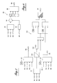
- the figure 2 presents an open loop management of the compromise between the NO x Low and Low Part modes, comprising a severity descriptor of the rolling 10 receiving different groups of information on the operation of the vehicle, comprising a first group 12 having the speed and acceleration of the vehicle, and the engine speed, a second group 14 having parameters of the engine thermal and the exhaust line, and a third group 16 with other varied information.
- the roll severity descriptor 10 processes this received information, and transmits the result 22 to an engine control system 18 including mappings which make it possible to establish a priori the operating point of the engine 20 giving the best compromise between the NO modes. x Low and Low Share. An open loop tradeoff is achieved, which takes into account only the information received at a given time.
- the figure 3 presents the same management, including in addition the current constraints added by the dilution of the fuel in the engine oil, for the regeneration of the particulate filter, so as to vary in the adjustment triangle 2 the weight of the Low Part mode based the severity of the ride.
- the scheme includes a PI-type dilution control, receiving information on the maximum allowable dilution 32, the mileage remaining before the next oil change 34 and the current dilution 36, and the result 22 of the severity descriptor. of rolling 10, to obtain the respective weight of the Low Part mode 38.
- the respective weight of the Low Part Mode 38 is then combined 44 using multiplying coefficients, with the respective weight of the NO x Low mode 40 given by a map 42 using the results 22 of the rolling severity descriptor 10, to obtain the point of departure. engine operation 20.
- Dilution regulation allows the dilution to be taken into account in the choice of the compromise, with a regulation of the rate of increase of the current dilution compared to a target that it should have to respect the maximum dilution criterion at the time of dilution. next drain, if the driver continues to drive in the same way. This allows the changeover to NO x Low mode earlier if the rate of increase or derived from the current dilution is lower than that actually needed. The margin given by this lower current dilution is then used to give a greater weight to the NO x Low mode in order to favor this mode and to save urea.
- the dilution control 30 implemented will force to return to a compromise favoring the Low Part mode by giving a respective weight. more important in this mode, to save the engine from excessive dilution and avoid breaking it, even if it means consuming more urea, and risking the breakdown of urea.
- the figure 4 shows in detail an exemplary dilution regulation 30, which is implemented after each regeneration of the particulate filter, at the time when the dilution of the oil is the largest following a complementary injection of fuel in the engine.
- Dilution control 30 includes a target dilution calculation 50 receiving result 22 of the rolling severity descriptor, the maximum allowable dilution 32, the mileage remaining before the next emptying 34 and the current dilution 36.
- the target dilution calculation 50 can based on a simple division from the dilution reserve, which is equal to the maximum allowable dilution minus the current dilution, divided by the distance remaining before the next oil change.
- the target dilution calculation 50 can also be based on a more complex calculation using a nonlinear but logarithmic projection of this dilution, also taking into account the evaporation of the fuel which is more and more marked with the increase of the dilution, and the severity of the driving.
- the dilution regulation 30 also comprises a dilution calculation performed 52, receiving the current dilution 36.
- the dilution control performed 52 is based on a simple calculation of discrete derivative, and a sliding average on several successive regenerations of index n ".
- RGn ": dDilution / dx ⁇ not Dilution_RGn - Dilution_RGn - 1 / xn - xn - 1
- the figure 5 presents the same management, including in addition the current constraints added by the current consumption of urea.
- the diagram comprises a regulation of urea consumption 60 of the type PI, relative to the target average level that it should have, receiving information on the volume of urea remaining in the reservoir 62, on the mileage remaining before filling the container.
- the figure 6 shows in detail an example of regulation of urea consumption 60 periodically implemented after distances traveled which are constant, representing the order of magnitude between two RG regenerations, a few hundred kilometers.
- the urea consumption control 60 comprises a target urea consumption average calculation 80 receiving the result 22 of the rolling severity descriptor, the volume of urea remaining in the reservoir 62, the mileage remaining before filling. urea 64, and the current consumption of urea 66.
- the urea consumption control 60 also comprises a calculated average consumption calculation 82, receiving the current consumption 66 to calculate an average consumption established over several values.
- the figure 7 presents the use of the two regulations described above, which allow, in the case where the respective weights of the modes NOx Low and Part Low are both low, to favor the provision of fuel consumption by giving a respective weight higher to the mode CO 2 Low. We then move the centroid 4 of the triangle 2, closer to the top CO 2 Low.
- the scheme of the figure 7 taken from that of the figure 5 furthermore comprises a map 100 which receives the information of the rolling severity descriptor 10, in order to deliver, depending on the rolling conditions in progress, a weight CO respective mode 2 Low 102.
- the three respective weights modes NOx Bas 68, Part 38 Low Low 102 and CO 2 are then combined 104 using multiplier coefficients, to obtain the operating point of the engine 20.
- the respective maximum weight of CO 2 Low mode must be lower than the respective weight of the NO x Low mode, which is itself lower than the respective weight of the Part mode Low. This ensures the best compromise between the emissions at the source of the different pollutants, taking into account the current state of the pollution control systems, compared to their initially planned state for that moment.
- This process also requires more mapping describing the emissions of pollutants at the source, to achieve at least two or three compromises between nitrogen oxides NOx, particulate matter and carbon dioxide CO 2 , however these maps generally already exist because they are necessary to perform upstream engine developments.
- the optimization method according to the invention is integrated in the management computer of the engine, which represents an economical solution.
Landscapes
- Engineering & Computer Science (AREA)
- Chemical & Material Sciences (AREA)
- Combustion & Propulsion (AREA)
- Mechanical Engineering (AREA)
- General Engineering & Computer Science (AREA)
- Chemical Kinetics & Catalysis (AREA)
- Health & Medical Sciences (AREA)
- Toxicology (AREA)
- Exhaust Gas After Treatment (AREA)
Applications Claiming Priority (1)
| Application Number | Priority Date | Filing Date | Title |
|---|---|---|---|
| FR1252476A FR2988438B1 (fr) | 2012-03-20 | 2012-03-20 | Procede de fonctionnement d'un moteur diesel comprenant des systemes de depollution |
Publications (1)
| Publication Number | Publication Date |
|---|---|
| EP2642105A1 true EP2642105A1 (de) | 2013-09-25 |
Family
ID=47710052
Family Applications (1)
| Application Number | Title | Priority Date | Filing Date |
|---|---|---|---|
| EP13155661.5A Withdrawn EP2642105A1 (de) | 2012-03-20 | 2013-02-18 | Verfahren zum Betrieb eines Dieselmotors, das mit Abgasreinigungssystemen ausgestattet ist |
Country Status (2)
| Country | Link |
|---|---|
| EP (1) | EP2642105A1 (de) |
| FR (1) | FR2988438B1 (de) |
Citations (7)
| Publication number | Priority date | Publication date | Assignee | Title |
|---|---|---|---|---|
| EP1568872A1 (de) * | 2004-02-27 | 2005-08-31 | Peugeot Citroen Automobiles S.A. | System für die Unterstützung der Regeneration einer Abgasanlage |
| FR2900967A1 (fr) * | 2006-05-11 | 2007-11-16 | Peugeot Citroen Automobiles Sa | Procede de pilotage du fonctionnement d'un moteur a explosion, ligne d'echappement pour sa mise en oeuvre et vehicule ainsi equipe. |
| EP1908947A2 (de) * | 2006-10-02 | 2008-04-09 | Nissan Motor Co., Ltd. | Verfahren und Vorrichtung zur Abgastemperaturregelung und System für Brennkraftmaschine |
| WO2009014599A2 (en) | 2007-07-19 | 2009-01-29 | Corning Incorporated | Regeneration method for ceramic honeycomb structures |
| FR2926323A1 (fr) * | 2008-01-11 | 2009-07-17 | Renault Sas | Procede de gestion d'un piege a oxydes d'azote afin d'assurer un intervalle de vidange minimal |
| EP2472088A1 (de) * | 2011-01-04 | 2012-07-04 | Peugeot Citroën Automobiles SA | Regelverfahren für einen Motor welches eine maximale Ölverdünnung bis zur nächsten Inspektion zulässt |
| EP2604832A1 (de) * | 2011-12-12 | 2013-06-19 | Peugeot Citroën Automobiles Sa | Verfahren zur Optimierung des Verbrennungsverfahrens von umweltverschmutzenden Partikeln, die von einer Wärmekraftmaschine eines Fahrzeugs ausgestoßen werden |
-
2012
- 2012-03-20 FR FR1252476A patent/FR2988438B1/fr not_active Expired - Fee Related
-
2013
- 2013-02-18 EP EP13155661.5A patent/EP2642105A1/de not_active Withdrawn
Patent Citations (7)
| Publication number | Priority date | Publication date | Assignee | Title |
|---|---|---|---|---|
| EP1568872A1 (de) * | 2004-02-27 | 2005-08-31 | Peugeot Citroen Automobiles S.A. | System für die Unterstützung der Regeneration einer Abgasanlage |
| FR2900967A1 (fr) * | 2006-05-11 | 2007-11-16 | Peugeot Citroen Automobiles Sa | Procede de pilotage du fonctionnement d'un moteur a explosion, ligne d'echappement pour sa mise en oeuvre et vehicule ainsi equipe. |
| EP1908947A2 (de) * | 2006-10-02 | 2008-04-09 | Nissan Motor Co., Ltd. | Verfahren und Vorrichtung zur Abgastemperaturregelung und System für Brennkraftmaschine |
| WO2009014599A2 (en) | 2007-07-19 | 2009-01-29 | Corning Incorporated | Regeneration method for ceramic honeycomb structures |
| FR2926323A1 (fr) * | 2008-01-11 | 2009-07-17 | Renault Sas | Procede de gestion d'un piege a oxydes d'azote afin d'assurer un intervalle de vidange minimal |
| EP2472088A1 (de) * | 2011-01-04 | 2012-07-04 | Peugeot Citroën Automobiles SA | Regelverfahren für einen Motor welches eine maximale Ölverdünnung bis zur nächsten Inspektion zulässt |
| EP2604832A1 (de) * | 2011-12-12 | 2013-06-19 | Peugeot Citroën Automobiles Sa | Verfahren zur Optimierung des Verbrennungsverfahrens von umweltverschmutzenden Partikeln, die von einer Wärmekraftmaschine eines Fahrzeugs ausgestoßen werden |
Also Published As
| Publication number | Publication date |
|---|---|
| FR2988438B1 (fr) | 2014-04-18 |
| FR2988438A1 (fr) | 2013-09-27 |
Similar Documents
| Publication | Publication Date | Title |
|---|---|---|
| EP2274506B1 (de) | Verfahren zur korrektur von stickoxidemissionsmodellen | |
| FR3024885A1 (fr) | Procede et dispositif de reduction des emissions d'oxydes d'azote et d'ammoniac dans un systeme de post-traitement des gaz d'echappement d'un moteur thermique pendant les alternances de charge | |
| EP1536109B1 (de) | Verfahren und Vorrichtung zur Steuerung der Regenerierung eines Partikelfilters in einer Verbrennungsmotorabgaseinrichtung | |
| WO2008006984A1 (fr) | Procede de controle de la consommation d'uree pour systeme de traitement d'oxydes d'azote | |
| EP2585701B1 (de) | Verfahren zr anpassung der einstellungen eines motors auf grundlage des verbrauchs eines stickoxidreduktionsmittels | |
| WO2007090975A2 (fr) | SYSTEME ET PROCEDE D'ELIMINATION DE SOx (OXYDE DE SOUFRE), SUPERVISEUR POUR CE SYSTEME | |
| FR2884767A1 (fr) | Procede de gestion de la ligne de transmission comportant une machine electrique et dispositif pour la mise en oeuvre du procede | |
| EP2472088B1 (de) | Regelverfahren für einen Motor welches eine maximale Ölverdünnung bis zur nächsten Inspektion zulässt | |
| EP2642105A1 (de) | Verfahren zum Betrieb eines Dieselmotors, das mit Abgasreinigungssystemen ausgestattet ist | |
| FR2852627A1 (fr) | Procede d'epuration des gaz d'echappement pour des moteurs a combustion interne a melange pauvre | |
| WO2018096292A1 (fr) | Procédé d'optimisation d'une dépollution en oxydes d'azote des gaz dans une ligne d'échappement de moteur selon une réduction catalytique sélective | |
| FR2929644A1 (fr) | Procede de controle de la consommation d'agent reducteur dans un systeme scr | |
| FR2936995A3 (fr) | Regeneration d'un dispositif de post-traitement assistee par navigateur | |
| WO2011114028A1 (fr) | Procede de controle des emissions polluantes d'un moteur hybride de vehicule | |
| EP3073080B1 (de) | Abgasnachbehandlungsverfahren eines kraftfahrzeugs | |
| FR2970040A1 (fr) | Dispositif de regeneration d'un filtre a particules equipant une ligne d'echappement d'un moteur thermique | |
| EP2771551B1 (de) | Verfahren und vorrichtung zur einstellung des verbrauchs eines verschmutzungsentfernungsmittels durch eine abgasleitung eines hybridfahrzeugs entsprechend verschiedenen antriebsmodi | |
| FR3073428B1 (fr) | Procede d’adaptation de l’additivation aux emissions pour aide a la regeneration d’un filtre a particules | |
| EP3847353A1 (de) | Vorrichtung und verfahren zur steuerung des betriebszustandes einer verarbeitungseinheit für gasförmige abfälle von einer abgasleitung eines verbrennungsmotors | |
| FR3061515A1 (fr) | Procede d’injection d’uree dans un catalyseur de reduction selective et systeme de post-traitement des gaz d’echappement d’un moteur thermique | |
| EP2097622B1 (de) | System und verfahren zur regeneration einer vorrichtung zum katalytischen zwischenspeichern von stickoxiden | |
| FR2983522A1 (fr) | Regeneration d'un dispositif de post-traitement de gaz d'echappement a modulation de temperature de consigne | |
| FR3081508A1 (fr) | Procédé de gestion d’un catalyseur-accumulateur NOx | |
| FR2930967A1 (fr) | Systeme et procede d'optimisation de l'automate de declenchement des purges soufre | |
| FR3085056A1 (fr) | Procede de planification de la regeneration d’un filtre a particules sur un trajet de roulage |
Legal Events
| Date | Code | Title | Description |
|---|---|---|---|
| PUAI | Public reference made under article 153(3) epc to a published international application that has entered the european phase |
Free format text: ORIGINAL CODE: 0009012 |
|
| AK | Designated contracting states |
Kind code of ref document: A1 Designated state(s): AL AT BE BG CH CY CZ DE DK EE ES FI FR GB GR HR HU IE IS IT LI LT LU LV MC MK MT NL NO PL PT RO RS SE SI SK SM TR |
|
| AX | Request for extension of the european patent |
Extension state: BA ME |
|
| 17P | Request for examination filed |
Effective date: 20140310 |
|
| RBV | Designated contracting states (corrected) |
Designated state(s): AL AT BE BG CH CY CZ DE DK EE ES FI FR GB GR HR HU IE IS IT LI LT LU LV MC MK MT NL NO PL PT RO RS SE SI SK SM TR |
|
| RAP1 | Party data changed (applicant data changed or rights of an application transferred) |
Owner name: PSA AUTOMOBILES SA |
|
| GRAP | Despatch of communication of intention to grant a patent |
Free format text: ORIGINAL CODE: EPIDOSNIGR1 |
|
| RIC1 | Information provided on ipc code assigned before grant |
Ipc: F02D 41/40 20060101ALI20180731BHEP Ipc: F01N 9/00 20060101ALI20180731BHEP Ipc: F02D 41/02 20060101AFI20180731BHEP Ipc: F01N 3/20 20060101ALI20180731BHEP |
|
| INTG | Intention to grant announced |
Effective date: 20180823 |
|
| STAA | Information on the status of an ep patent application or granted ep patent |
Free format text: STATUS: THE APPLICATION IS DEEMED TO BE WITHDRAWN |
|
| 18D | Application deemed to be withdrawn |
Effective date: 20190103 |