EP2642365B1 - Steuerungsvorrichtung für industrielle Maschinen - Google Patents
Steuerungsvorrichtung für industrielle Maschinen Download PDFInfo
- Publication number
- EP2642365B1 EP2642365B1 EP12382100.1A EP12382100A EP2642365B1 EP 2642365 B1 EP2642365 B1 EP 2642365B1 EP 12382100 A EP12382100 A EP 12382100A EP 2642365 B1 EP2642365 B1 EP 2642365B1
- Authority
- EP
- European Patent Office
- Prior art keywords
- runner
- radial
- plate element
- contact
- operating knob
- Prior art date
- Legal status (The legal status is an assumption and is not a legal conclusion. Google has not performed a legal analysis and makes no representation as to the accuracy of the status listed.)
- Active
Links
Images



Classifications
-
- G—PHYSICS
- G05—CONTROLLING; REGULATING
- G05G—CONTROL DEVICES OR SYSTEMS INSOFAR AS CHARACTERISED BY MECHANICAL FEATURES ONLY
- G05G1/00—Controlling members, e.g. knobs or handles; Assemblies or arrangements thereof; Indicating position of controlling members
- G05G1/04—Controlling members for hand actuation by pivoting movement, e.g. levers
-
- G—PHYSICS
- G05—CONTROLLING; REGULATING
- G05G—CONTROL DEVICES OR SYSTEMS INSOFAR AS CHARACTERISED BY MECHANICAL FEATURES ONLY
- G05G9/00—Manually-actuated control mechanisms provided with one single controlling member co-operating with two or more controlled members, e.g. selectively, simultaneously
- G05G9/02—Manually-actuated control mechanisms provided with one single controlling member co-operating with two or more controlled members, e.g. selectively, simultaneously the controlling member being movable in different independent ways, movement in each individual way actuating one controlled member only
- G05G9/04—Manually-actuated control mechanisms provided with one single controlling member co-operating with two or more controlled members, e.g. selectively, simultaneously the controlling member being movable in different independent ways, movement in each individual way actuating one controlled member only in which movement in two or more ways can occur simultaneously
- G05G9/047—Manually-actuated control mechanisms provided with one single controlling member co-operating with two or more controlled members, e.g. selectively, simultaneously the controlling member being movable in different independent ways, movement in each individual way actuating one controlled member only in which movement in two or more ways can occur simultaneously the controlling member being movable by hand about orthogonal axes, e.g. joysticks
-
- Y—GENERAL TAGGING OF NEW TECHNOLOGICAL DEVELOPMENTS; GENERAL TAGGING OF CROSS-SECTIONAL TECHNOLOGIES SPANNING OVER SEVERAL SECTIONS OF THE IPC; TECHNICAL SUBJECTS COVERED BY FORMER USPC CROSS-REFERENCE ART COLLECTIONS [XRACs] AND DIGESTS
- Y10—TECHNICAL SUBJECTS COVERED BY FORMER USPC
- Y10T—TECHNICAL SUBJECTS COVERED BY FORMER US CLASSIFICATION
- Y10T74/00—Machine element or mechanism
- Y10T74/20—Control lever and linkage systems
- Y10T74/20012—Multiple controlled elements
- Y10T74/20201—Control moves in two planes
Definitions
- the present invention relates to a control device for industrial machinery; where said device has an application in controlling cranes, lifting machinery and the like, belonging to the industrial sector.
- control device for industrial machinery object of invention is to adapt a mini-joystick (for example a conventional mini-joystick such as those used in computers or consoles) in industrial and therefore aggressive environments with respect to the device and its correct operation, such that it is small-sized and capable of precisely transmitting the position of the drive shaft of the mini-joystick to the operator, all with simple and economical elements, forming an ergonomic and resistant device according to said applications in industrial environments.
- a mini-joystick for example a conventional mini-joystick such as those used in computers or consoles
- control devices used today in controlling cranes, lifting machinery or the like are large-sized joystick type control devices, and are aimed at being mounted in desk type radio control transmitters because small joystick devices, which are more suited to being installed in pushbutton type portable control transmitters, they do not have the ergonomics and robustness necessary for correctly operating and controlling the crane type machinery or the like.
- European patent application with publication number EP-999487 where a joystick type control device with defined and specific positions is described; where said device comprises a large-sized surrounding structure and a plurality of inner elastic elements defining the fixed positions of said device, having drawbacks similar to the aforementioned international application with respect to being large-sized and with high-cost and maintenance custom-made elements, and where it additionally requires a large number of elastic elements which make the device shown even more expensive.
- Korean patent application with publication number KR-2004/0039108 wherein a small-sized joystick type control device suitable for being installed in a pushbutton type radio control transmitter is described, having the advantages of being ergonomic and easily transportable, but lacking suitable strength for industrial environments due to the fragility of the operating or drive shaft of said device, such that it is not adapted to the field of application of the device object of invention.
- the present invention relates to a control device for industrial machinery which notably solves the drawbacks described above and allows adapting a conventional mini-joystick for use in industrial environments and for controlling lifting machinery and for general use, such that a handling-resistant and ergonomic device is provided.
- the control device for industrial machinery proposed by the invention comprises:
- Novel technical features include the combination of the runner in contact with the plate element because the runner is directly linked with the movement of the drive shaft of the mini-joystick, and when the runner moves, it comes into contact with specific areas of the plate element which can comprise a series of geometries interacting with the runner and are perceived by the user handling the device object of invention, such that even when the user is wearing safety gloves or the like, he is capable of very easily perceiving and differentiating the position of the drive shaft of the mini-joystick.
- mini-joystick which will preferably be a conventional mini-joystick which are easily found on the market and have an application in very diverse uses such as a joystick for video consoles, computers, for handling onboard vehicle computers, mobile telephones, etc. Therefore, the cost is not high and does not involve making a particular and unique joystick particular for the device object of invention, unlike in the mentioned background.
- the overall size of the device object of the invention will be substantially much smaller than control devices for machinery used today in the industrial sector, with the subsequent advantage of being able to be easily transported and be included in conventional remote control pushbutton devices.
- the plate element can be formed from, or be part of, the casing itself such that they form a single element and the overall manufacturing cost of the device object of invention is reduced.
- a first configuration contemplates that the surface of the plate element in contact with the radial flaring is smooth, thereby achieving continuous movement of the drive shaft throughout 360°, without any interference. This is preferably valid for non-aggressive environments, such that the user does not need safety gloves that can reduce sensitivity of perceiving the movement of said drive shaft.
- a second configuration contemplates that the surface of the plate element in contact with the radial flaring of the runner comprises at least one notch in a radial direction, such that a continuous movement of the drive shaft throughout 360° is achieved but it results in a stimulus that the user perceives every time the radial flaring passes over said at least one notch; being able to contemplate, for example, a notch every 45° so that the user perfectly perceives the position of the operating shaft without needing to remove respective safety gloves; and where each notch can additionally comprise at least one recess perpendicular to it, defining steps perceivable by the user and considerably increasing the degree of sensitivity of the device.
- a third configuration contemplates that the surface of the plate element in contact with the radial flaring of the runner comprises at least one circumferential groove, such that a continuous movement of the drive shaft throughout 360° is achieved but it results in a stimulus differentiating two areas along a radial path such that, for example, said at least one circumferential groove can demarcate two different speeds to be chosen by the user, which are very easily perceived.
- a fourth configuration contemplates that the surface of the plate element in contact with the radial flaring of the runner comprises a geometric configuration in sectors, such that the operating shaft rapidly tends to move towards the area limited by the sectors, there preferably being four sectors in the form of a four leaf clover rapidly and precisely demarcating the preferential north-south-east-west positions.
- a fifth configuration contemplates that the surface of the plate element in contact with the radial flaring of the runner comprises a configuration of sectors defined by radial notches, with the particularity that in the preferential directions (for example N, S, E, W) the two contiguous notches defining the sector of the preferential direction are separated by an angle greater than the notches corresponding to non-preferential directions (for example NW, NE, SE, SW).
- the notches demarcating the sectors of preferential directions can be separated by an angle greater than 47.5° (defining an angular sector greater than 47.5° in each preferential direction) and the notches demarcating non-preferential sectors can be separated by an angle of less than 42.5° (defining an angular sector in each non-preferential direction less than 42.5°).
- This design conveys to the user a continuous and step-less sensation in each of the possible operating directions and better guiding in the preferential directions.
- a sixth configuration contemplates that the surface of the plate element in contact with the radial flaring comprises a series of double notches in a radial direction, i.e., each notch comprises two ramps or steps allowing the user to have a sensation of two steps in each of the operating directions.
- the possibility of the surface of the radial flaring of the runner in contact with the surface of the plate element comprising at least one protrusion, whether in a radial or circumferential direction, is contemplated, such that the plate element comprises a smooth surface in contact with the radial flaring of the runner, and it is this radial flaring having said at least one protrusion intended for indicating specific positions or speeds of the device object of invention.
- the device comprising an operating knob which can be coupled on the runner
- the knob is directly linked with the movement of the runner and the movements are also transmitted in both directions: from the operating knob to the drive shaft, and from the irregularities exiting both in the plate and in the runner to said operating knob for being perceived by the user.
- the invention is based on the operating knob comprising a plurality of merlon or peak type geometric irregularities at its upper end to assure proper gripping of the operating knob by the user.
- the operating knob comprises a series of protrusions on its side surface, smooth areas being defined between two contiguous protrusions such that when supporting the operating finger in a well demarcated area or surface (protrusion or smooth area) the force can be better directed in the suitable direction.
- the protrusions can be configured such that they coincide with the preferential directions and the smooth areas coincide with the non-preferential directions or vice versa according to user preferences.
- the knob can also incorporate a central lug in correspondence with the drive shaft which allows defining a good support surface for the user's finger.
- It additionally comprises at least one elastic element which is attached at one end to the runner, and is attached at the other end to the operating knob, such that it allows the backward movement of the operating knob on which the operator can act with his/her thumb for activating/deactivating characteristic functions of the mini-joystick.
- an elastic part at least partially covering the device object of invention is contemplated, providing mechanical strength and leak-tightness fundamental for aggressive work environments on which the device of invention is focused.
- the control device for industrial machinery proposed by the invention constitutes an advance in control devices known until now and solves in a fully satisfactorily manner the aforementioned drawbacks in that it provides a small-sized device, capable of being portable, formed by a plurality of easy to maintain simple and economical elements, and capable of being used in aggressive environments such as in the industrial sector and lifting machinery sector.
- Figure 4 shows a series of possible embodiments of the plate element (3).
- the surface (3a) of the plate element (3) in contact with the radial flaring (4a) comprises eight radial notches (3"") defining eight sectors.
- the preferential directions for example N, S, E, W
- the two contiguous notches defining the sector of the preferential direction are separated by an angle greater than 47.5°
- the notches corresponding to non-preferential directions for example NW, NE, SE, SW
- each notch comprises two ramps or steps allowing the user to have a sensation of two steps in each of the eight possible operating directions.
- These notches can be separated by different angles as in the embodiment of Figure 4e defining preferential operating sectors and non-preferential operating sectors.
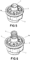
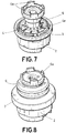
- the invention is depicted in Figure 7 in which the operating knob (6) comprises four merlons (6a) improving the gripping of said operating knob (6) by the user.
- the operating knob (6') comprises a series of protrusions (6'a) on its side surface, contiguous, smooth areas (6'b) being defined between two protrusions (6'a) such that when the operating finger rests on a protrusion (6'a) or on a smooth area (6'b) it allows better directing the force in the suitable direction.
- the protrusions (6'a) can be configured such that they coincide with the preferential directions and the smooth areas (6'b) coincide with the non-preferential directions or vice versa according to user preferences.
- the operating knob (6') is also incorporate a central lug (6'c) in correspondence with the drive shaft (1a) which allows defining a good support surface for the user's finger.
Landscapes
- Physics & Mathematics (AREA)
- General Physics & Mathematics (AREA)
- Engineering & Computer Science (AREA)
- Automation & Control Theory (AREA)
- Position Input By Displaying (AREA)
- Mechanical Control Devices (AREA)
Claims (14)
- Steuerungsvorrichtung für industrielle Maschinen, umfassend:einen Mini-Joystick (1), umfassend eine Antriebswelle (1a),ein Gehäuse (2), das mindestens teilweise den Mini-Joystick (1) abdeckt, undeinen Bedienknopf (6);ein Plattenelement (3), das auf dem Gehäuse (2) aufliegt, wobei das Plattenelement (3) eine zentrale Durchgangsbohrung (3b) umfasst, die den Durchgang der Antriebswelle (1a) durch die zentrale Durchgangsbohrung (3b) erlaubt,einen hohlen röhrenförmigen Läufer (4), der innen die Antriebswelle (1a) umfasst, sodass, wenn sich der Läufer (4) bewegt, die Antriebswelle (1a) sich ebenfalls bewegt; wobei einer der Unterbauten des Läufers (4) eine radiale Aufweitung (4a) umfasst, und wobei die radiale Aufweitung (4a) auf einer Fläche (3a) ruht, die zu der Platte gehört, und wobei die Vorrichtung dadurch gekennzeichnet ist, dass sie zusätzlich Folgendes umfassteinen elastischen Teil (7), der die Steuerungsvorrichtung mindestens teilweise abdeckt, undmindestens ein elastisches Element (5), das an einem Ende an dem Läufer (4) befestigt ist und an dem anderen Ende an dem Bedienknopf (6) befestigt ist.
- Vorrichtung nach Anspruch 1, wobei die Fläche (3a) des Plattenelements (3), die in Kontakt mit der radialen Aufweitung (4a) steht, glatt ist.
- Vorrichtung nach Anspruch 1, wobei die Fläche (3a) des Plattenelements (3), die in Kontakt mit der radialen Aufweitung (4a) des Läufers (4) steht, mindestens eine Einkerbung (3') in einer radialen Richtung umfasst.
- Vorrichtung nach Anspruch 3, wobei die mindestens eine Einkerbung (3'), die in einer radialen Richtung verläuft und zu der Fläche (3a) des Plattenelements (3) gehört, die in Kontakt mit der radialen Aufweitung (4a) des Läufers (4) steht, mindestens eine Aussparung umfasst, die senkrecht zu der mindestens einen Einkerbung (3') ist.
- Vorrichtung nach Anspruch 1, wobei die Fläche (3a) des Plattenelements (3), die in Kontakt mit der radialen Aufweitung (4a) des Läufers (4) steht, mindestens eine Umfangsnut (3") umfasst.
- Vorrichtung nach Anspruch 1, wobei die Fläche (3a) des Plattenelements (3), die in Kontakt mit der radialen Aufweitung (4a) des Läufers (4) steht, eine geometrische Ausgestaltung in Sektoren (3"') umfasst.
- Vorrichtung nach Anspruch 1, wobei die Fläche (3a) des Plattenelements (3), die in Kontakt mit der radialen Aufweitung (4a) des Läufers (4) steht, eine Ausgestaltung von Sektoren umfasst, die durch radiale Einkerbungen (3"") bestimmt sind, wobei zwei aneinander angrenzende Einkerbungen einen bevorzugten Sektor bestimmen, der durch einen Winkel größer als 47,5° getrennt ist.
- Vorrichtung nach Anspruch 7, wobei die radialen Einkerbungen (3""') zwei Abschrägungen umfassen, die es dem Benutzer erlauben, ein Empfinden von zwei Schritten in jeder der Bedienrichtungen zu haben.
- Vorrichtung nach einem der vorhergehenden Ansprüche, wobei die Fläche der radialen Aufweitung (4a) des Läufers (4), die in Kontakt mit der Fläche (3a) des Plattenelements (3) steht, glatt ist.
- Vorrichtung nach Anspruch 1, wobei der Bedienknopf (6) auf den Läufer (4) koppelbar ist.
- Vorrichtung nach einem der Ansprüche 1 bis 10, wobei der Bedienknopf (6) eine Vielzahl von geometrischen Unregelmäßigkeiten an seinem oberen Ende umfasst.
- Vorrichtung nach Anspruch 11, wobei der Bedienknopf (6) eine Vielzahl von Zinnen (6a) umfasst, um das ordnungsgemäße Greifen des Bedienknopfs (6) durch den Benutzer sicherzustellen.
- Vorrichtung nach einem der Ansprüche 10 bis 12, wobei der Bedienknopf (6') eine Reihe von Vorsprüngen (6'a) an seiner Seitenfläche umfasst, wobei aneinandergrenzende glatte Bereiche (6'b) zwischen zwei Vorsprüngen (6'a) definiert sind, sodass an den Vorsprüngen (6'a) oder den glatten Bereichen (6'b) agiert werden kann.
- Vorrichtung nach Anspruch 13, wobei der Bedienknopf (6') zusätzlich einen zentralen Mitnehmer (6'c) entsprechend der Antriebswelle (1a) umfasst, wodurch ermöglicht wird, eine gute Stützfläche für den Finger des Benutzers zu definieren.
Priority Applications (3)
| Application Number | Priority Date | Filing Date | Title |
|---|---|---|---|
| EP12382100.1A EP2642365B1 (de) | 2012-03-20 | 2012-03-20 | Steuerungsvorrichtung für industrielle Maschinen |
| ES12382100.1T ES2645625T3 (es) | 2012-03-20 | 2012-03-20 | Dispositivo de control para maquinaria industrial |
| US13/796,042 US20130247702A1 (en) | 2012-03-20 | 2013-03-12 | Control device for industrial machinery |
Applications Claiming Priority (1)
| Application Number | Priority Date | Filing Date | Title |
|---|---|---|---|
| EP12382100.1A EP2642365B1 (de) | 2012-03-20 | 2012-03-20 | Steuerungsvorrichtung für industrielle Maschinen |
Publications (2)
| Publication Number | Publication Date |
|---|---|
| EP2642365A1 EP2642365A1 (de) | 2013-09-25 |
| EP2642365B1 true EP2642365B1 (de) | 2017-08-16 |
Family
ID=45937162
Family Applications (1)
| Application Number | Title | Priority Date | Filing Date |
|---|---|---|---|
| EP12382100.1A Active EP2642365B1 (de) | 2012-03-20 | 2012-03-20 | Steuerungsvorrichtung für industrielle Maschinen |
Country Status (3)
| Country | Link |
|---|---|
| US (1) | US20130247702A1 (de) |
| EP (1) | EP2642365B1 (de) |
| ES (1) | ES2645625T3 (de) |
Families Citing this family (3)
| Publication number | Priority date | Publication date | Assignee | Title |
|---|---|---|---|---|
| US9868058B2 (en) * | 2015-06-30 | 2018-01-16 | Microsoft Technology Licensing, Llc | Thumbstick with adjustable tension |
| DE102019125223A1 (de) | 2019-09-19 | 2021-03-25 | Konecranes Global Corp. | Vorrichtung zur Handbetätigung einer Maschine, vorzugsweise eines Hebezeugs oder Krans |
| CN111606210A (zh) * | 2020-06-01 | 2020-09-01 | 郭冰冰 | 一种起重器的控制装置 |
Family Cites Families (15)
| Publication number | Priority date | Publication date | Assignee | Title |
|---|---|---|---|---|
| SE436231B (sv) * | 1980-07-04 | 1984-11-19 | Zettergren Ted Ab | Anordning vid flerlegesspak |
| SE8104509L (sv) | 1981-07-23 | 1983-01-24 | Aokerstroems Bjoerbo Ab | Anordning vid en manuell, till ett ursprungslege automatiskt atergaende manoverspak |
| US5541622A (en) * | 1990-07-24 | 1996-07-30 | Incontrol Solutions, Inc. | Miniature isometric joystick |
| USD361257S (en) * | 1993-08-03 | 1995-08-15 | Newell Operating Company | Knob |
| USD383523S (en) * | 1995-09-22 | 1997-09-09 | Emhart Inc. | Handle |
| US6082212A (en) * | 1997-07-25 | 2000-07-04 | Crown Equipment Corporation | Multi-function control handle |
| EP0999487A2 (de) | 1998-11-06 | 2000-05-10 | Midway Amusement Games, LLC | Analoger Steuerknüppel |
| USD451361S1 (en) * | 2000-10-31 | 2001-12-04 | Hon Hai Precision Ind. Co., Ltd. | Knob |
| US6624806B2 (en) * | 2001-08-27 | 2003-09-23 | Weistech Technology Co., Ltd. | Joystick capable of controlling direction rudder and accelerator synchronously |
| USD473501S1 (en) * | 2002-01-30 | 2003-04-22 | Kabushiki Kaisha Carmate | Gear shift knob for automobile |
| KR20040039108A (ko) | 2002-11-01 | 2004-05-10 | 삼성전자주식회사 | 조이스틱 내장 리모컨 |
| JP4360078B2 (ja) | 2002-11-14 | 2009-11-11 | ミツミ電機株式会社 | 小型ジョイスティック |
| USD485795S1 (en) * | 2003-01-10 | 2004-01-27 | Charles Edward Murray | Gear shift knob |
| FR2942052B1 (fr) | 2009-02-12 | 2014-08-01 | Guillemot Corp | Mini-joystick a effet hall a detection d'appui, et dispositif de controle correspondant |
| JP5224076B2 (ja) * | 2011-03-24 | 2013-07-03 | 株式会社デンソー | 操作入力装置 |
-
2012
- 2012-03-20 EP EP12382100.1A patent/EP2642365B1/de active Active
- 2012-03-20 ES ES12382100.1T patent/ES2645625T3/es active Active
-
2013
- 2013-03-12 US US13/796,042 patent/US20130247702A1/en not_active Abandoned
Also Published As
| Publication number | Publication date |
|---|---|
| EP2642365A1 (de) | 2013-09-25 |
| ES2645625T3 (es) | 2017-12-07 |
| US20130247702A1 (en) | 2013-09-26 |
Similar Documents
| Publication | Publication Date | Title |
|---|---|---|
| EP1988559B1 (de) | Schalter | |
| EP2289730B1 (de) | Multifunktionseingabegerät | |
| US9891651B2 (en) | Rotatable input mechanism having adjustable output | |
| JP3197920U (ja) | ポータブルメディア装置のためのワイヤレスリモートコントロール装置 | |
| EP3133628B1 (de) | Eingabevorrichtung | |
| US9630101B2 (en) | Operating device | |
| EP2642365A1 (de) | Steuerungsvorrichtung für industrielle Maschinen | |
| US9292033B2 (en) | Force-feedback plane slide input device | |
| JP2014052664A (ja) | 操作子及び操作装置 | |
| EP2019403B1 (de) | Elektrischer Schalter mit mehreren Schaltkanälen | |
| CN204563570U (zh) | 摇杆和按键二合一的游戏手柄 | |
| KR102633219B1 (ko) | 인풋 디바이스 | |
| KR20160120422A (ko) | 오토바이용 핸들을 활용한 스마트 기기 리모트 컨트롤러 | |
| JP2013254615A (ja) | キースイッチ装置およびキーボード | |
| CN111606210A (zh) | 一种起重器的控制装置 | |
| EP2088492A2 (de) | Manuelle Eingabevorrichtung | |
| EP3180679B1 (de) | Benutzeroberfläche für ein kommunikationssystem | |
| US10061398B1 (en) | Ergonomic computer mouse | |
| JP2017127588A (ja) | 押しボタン用アタッチメント | |
| US20090308199A1 (en) | Rotary actuating mechanism having a selectable torque | |
| JP2012142219A (ja) | スイッチ装置 | |
| JP2009230177A (ja) | 入力装置およびそれを用いた携帯機器 | |
| JP2008181902A (ja) | 産業用ロボットの手持操作器 | |
| CN101751150A (zh) | 具有模式切换功能的薄型鼠标 |
Legal Events
| Date | Code | Title | Description |
|---|---|---|---|
| PUAI | Public reference made under article 153(3) epc to a published international application that has entered the european phase |
Free format text: ORIGINAL CODE: 0009012 |
|
| AK | Designated contracting states |
Kind code of ref document: A1 Designated state(s): AL AT BE BG CH CY CZ DE DK EE ES FI FR GB GR HR HU IE IS IT LI LT LU LV MC MK MT NL NO PL PT RO RS SE SI SK SM TR |
|
| AX | Request for extension of the european patent |
Extension state: BA ME |
|
| 17P | Request for examination filed |
Effective date: 20140304 |
|
| RBV | Designated contracting states (corrected) |
Designated state(s): AL AT BE BG CH CY CZ DE DK EE ES FI FR GB GR HR HU IE IS IT LI LT LU LV MC MK MT NL NO PL PT RO RS SE SI SK SM TR |
|
| GRAP | Despatch of communication of intention to grant a patent |
Free format text: ORIGINAL CODE: EPIDOSNIGR1 |
|
| STAA | Information on the status of an ep patent application or granted ep patent |
Free format text: STATUS: GRANT OF PATENT IS INTENDED |
|
| RAP1 | Party data changed (applicant data changed or rights of an application transferred) |
Owner name: ANGEL IGLESIAS, S.A. |
|
| INTG | Intention to grant announced |
Effective date: 20170308 |
|
| GRAS | Grant fee paid |
Free format text: ORIGINAL CODE: EPIDOSNIGR3 |
|
| GRAA | (expected) grant |
Free format text: ORIGINAL CODE: 0009210 |
|
| STAA | Information on the status of an ep patent application or granted ep patent |
Free format text: STATUS: THE PATENT HAS BEEN GRANTED |
|
| AK | Designated contracting states |
Kind code of ref document: B1 Designated state(s): AL AT BE BG CH CY CZ DE DK EE ES FI FR GB GR HR HU IE IS IT LI LT LU LV MC MK MT NL NO PL PT RO RS SE SI SK SM TR |
|
| REG | Reference to a national code |
Ref country code: GB Ref legal event code: FG4D |
|
| REG | Reference to a national code |
Ref country code: CH Ref legal event code: EP |
|
| REG | Reference to a national code |
Ref country code: IE Ref legal event code: FG4D |
|
| REG | Reference to a national code |
Ref country code: AT Ref legal event code: REF Ref document number: 919659 Country of ref document: AT Kind code of ref document: T Effective date: 20170915 |
|
| REG | Reference to a national code |
Ref country code: DE Ref legal event code: R096 Ref document number: 602012035939 Country of ref document: DE |
|
| REG | Reference to a national code |
Ref country code: ES Ref legal event code: FG2A Ref document number: 2645625 Country of ref document: ES Kind code of ref document: T3 Effective date: 20171207 |
|
| REG | Reference to a national code |
Ref country code: NL Ref legal event code: MP Effective date: 20170816 |
|
| REG | Reference to a national code |
Ref country code: LT Ref legal event code: MG4D |
|
| REG | Reference to a national code |
Ref country code: AT Ref legal event code: MK05 Ref document number: 919659 Country of ref document: AT Kind code of ref document: T Effective date: 20170816 |
|
| PG25 | Lapsed in a contracting state [announced via postgrant information from national office to epo] |
Ref country code: SE Free format text: LAPSE BECAUSE OF FAILURE TO SUBMIT A TRANSLATION OF THE DESCRIPTION OR TO PAY THE FEE WITHIN THE PRESCRIBED TIME-LIMIT Effective date: 20170816 Ref country code: LT Free format text: LAPSE BECAUSE OF FAILURE TO SUBMIT A TRANSLATION OF THE DESCRIPTION OR TO PAY THE FEE WITHIN THE PRESCRIBED TIME-LIMIT Effective date: 20170816 Ref country code: NO Free format text: LAPSE BECAUSE OF FAILURE TO SUBMIT A TRANSLATION OF THE DESCRIPTION OR TO PAY THE FEE WITHIN THE PRESCRIBED TIME-LIMIT Effective date: 20171116 Ref country code: NL Free format text: LAPSE BECAUSE OF FAILURE TO SUBMIT A TRANSLATION OF THE DESCRIPTION OR TO PAY THE FEE WITHIN THE PRESCRIBED TIME-LIMIT Effective date: 20170816 Ref country code: AT Free format text: LAPSE BECAUSE OF FAILURE TO SUBMIT A TRANSLATION OF THE DESCRIPTION OR TO PAY THE FEE WITHIN THE PRESCRIBED TIME-LIMIT Effective date: 20170816 |
|
| PG25 | Lapsed in a contracting state [announced via postgrant information from national office to epo] |
Ref country code: BG Free format text: LAPSE BECAUSE OF FAILURE TO SUBMIT A TRANSLATION OF THE DESCRIPTION OR TO PAY THE FEE WITHIN THE PRESCRIBED TIME-LIMIT Effective date: 20171116 Ref country code: LV Free format text: LAPSE BECAUSE OF FAILURE TO SUBMIT A TRANSLATION OF THE DESCRIPTION OR TO PAY THE FEE WITHIN THE PRESCRIBED TIME-LIMIT Effective date: 20170816 Ref country code: IS Free format text: LAPSE BECAUSE OF FAILURE TO SUBMIT A TRANSLATION OF THE DESCRIPTION OR TO PAY THE FEE WITHIN THE PRESCRIBED TIME-LIMIT Effective date: 20171216 Ref country code: PL Free format text: LAPSE BECAUSE OF FAILURE TO SUBMIT A TRANSLATION OF THE DESCRIPTION OR TO PAY THE FEE WITHIN THE PRESCRIBED TIME-LIMIT Effective date: 20170816 Ref country code: RS Free format text: LAPSE BECAUSE OF FAILURE TO SUBMIT A TRANSLATION OF THE DESCRIPTION OR TO PAY THE FEE WITHIN THE PRESCRIBED TIME-LIMIT Effective date: 20170816 |
|
| PG25 | Lapsed in a contracting state [announced via postgrant information from national office to epo] |
Ref country code: CZ Free format text: LAPSE BECAUSE OF FAILURE TO SUBMIT A TRANSLATION OF THE DESCRIPTION OR TO PAY THE FEE WITHIN THE PRESCRIBED TIME-LIMIT Effective date: 20170816 Ref country code: DK Free format text: LAPSE BECAUSE OF FAILURE TO SUBMIT A TRANSLATION OF THE DESCRIPTION OR TO PAY THE FEE WITHIN THE PRESCRIBED TIME-LIMIT Effective date: 20170816 Ref country code: RO Free format text: LAPSE BECAUSE OF FAILURE TO SUBMIT A TRANSLATION OF THE DESCRIPTION OR TO PAY THE FEE WITHIN THE PRESCRIBED TIME-LIMIT Effective date: 20170816 |
|
| REG | Reference to a national code |
Ref country code: DE Ref legal event code: R097 Ref document number: 602012035939 Country of ref document: DE |
|
| PG25 | Lapsed in a contracting state [announced via postgrant information from national office to epo] |
Ref country code: SK Free format text: LAPSE BECAUSE OF FAILURE TO SUBMIT A TRANSLATION OF THE DESCRIPTION OR TO PAY THE FEE WITHIN THE PRESCRIBED TIME-LIMIT Effective date: 20170816 Ref country code: EE Free format text: LAPSE BECAUSE OF FAILURE TO SUBMIT A TRANSLATION OF THE DESCRIPTION OR TO PAY THE FEE WITHIN THE PRESCRIBED TIME-LIMIT Effective date: 20170816 Ref country code: SM Free format text: LAPSE BECAUSE OF FAILURE TO SUBMIT A TRANSLATION OF THE DESCRIPTION OR TO PAY THE FEE WITHIN THE PRESCRIBED TIME-LIMIT Effective date: 20170816 Ref country code: IT Free format text: LAPSE BECAUSE OF FAILURE TO SUBMIT A TRANSLATION OF THE DESCRIPTION OR TO PAY THE FEE WITHIN THE PRESCRIBED TIME-LIMIT Effective date: 20170816 |
|
| PLBE | No opposition filed within time limit |
Free format text: ORIGINAL CODE: 0009261 |
|
| STAA | Information on the status of an ep patent application or granted ep patent |
Free format text: STATUS: NO OPPOSITION FILED WITHIN TIME LIMIT |
|
| REG | Reference to a national code |
Ref country code: DE Ref legal event code: R082 Ref document number: 602012035939 Country of ref document: DE Representative=s name: KALKOFF & PARTNER PATENTANWAELTE MBB, DE Ref country code: DE Ref legal event code: R082 Ref document number: 602012035939 Country of ref document: DE Representative=s name: KALKOFF & PARTNER PATENTANWAELTE, DE Ref country code: DE Ref legal event code: R081 Ref document number: 602012035939 Country of ref document: DE Owner name: IKUSI ELECTRONICA, S.L., ES Free format text: FORMER OWNER: ANGEL IGLESIAS, S.A., SAN SEBASTIAN, ES |
|
| 26N | No opposition filed |
Effective date: 20180517 |
|
| PG25 | Lapsed in a contracting state [announced via postgrant information from national office to epo] |
Ref country code: SI Free format text: LAPSE BECAUSE OF FAILURE TO SUBMIT A TRANSLATION OF THE DESCRIPTION OR TO PAY THE FEE WITHIN THE PRESCRIBED TIME-LIMIT Effective date: 20170816 |
|
| REG | Reference to a national code |
Ref country code: CH Ref legal event code: PL |
|
| REG | Reference to a national code |
Ref country code: ES Ref legal event code: PC2A Owner name: IKUSI ELECTRONICA, S.L. Effective date: 20181106 |
|
| GBPC | Gb: european patent ceased through non-payment of renewal fee |
Effective date: 20180320 |
|
| PG25 | Lapsed in a contracting state [announced via postgrant information from national office to epo] |
Ref country code: MC Free format text: LAPSE BECAUSE OF FAILURE TO SUBMIT A TRANSLATION OF THE DESCRIPTION OR TO PAY THE FEE WITHIN THE PRESCRIBED TIME-LIMIT Effective date: 20170816 |
|
| REG | Reference to a national code |
Ref country code: BE Ref legal event code: MM Effective date: 20180331 |
|
| REG | Reference to a national code |
Ref country code: IE Ref legal event code: MM4A |
|
| PG25 | Lapsed in a contracting state [announced via postgrant information from national office to epo] |
Ref country code: LU Free format text: LAPSE BECAUSE OF NON-PAYMENT OF DUE FEES Effective date: 20180320 |
|
| PG25 | Lapsed in a contracting state [announced via postgrant information from national office to epo] |
Ref country code: IE Free format text: LAPSE BECAUSE OF NON-PAYMENT OF DUE FEES Effective date: 20180320 |
|
| PG25 | Lapsed in a contracting state [announced via postgrant information from national office to epo] |
Ref country code: GB Free format text: LAPSE BECAUSE OF NON-PAYMENT OF DUE FEES Effective date: 20180320 Ref country code: LI Free format text: LAPSE BECAUSE OF NON-PAYMENT OF DUE FEES Effective date: 20180331 Ref country code: CH Free format text: LAPSE BECAUSE OF NON-PAYMENT OF DUE FEES Effective date: 20180331 Ref country code: BE Free format text: LAPSE BECAUSE OF NON-PAYMENT OF DUE FEES Effective date: 20180331 |
|
| PG25 | Lapsed in a contracting state [announced via postgrant information from national office to epo] |
Ref country code: FR Free format text: LAPSE BECAUSE OF NON-PAYMENT OF DUE FEES Effective date: 20180331 |
|
| PG25 | Lapsed in a contracting state [announced via postgrant information from national office to epo] |
Ref country code: MT Free format text: LAPSE BECAUSE OF NON-PAYMENT OF DUE FEES Effective date: 20180320 |
|
| PG25 | Lapsed in a contracting state [announced via postgrant information from national office to epo] |
Ref country code: TR Free format text: LAPSE BECAUSE OF FAILURE TO SUBMIT A TRANSLATION OF THE DESCRIPTION OR TO PAY THE FEE WITHIN THE PRESCRIBED TIME-LIMIT Effective date: 20170816 |
|
| PG25 | Lapsed in a contracting state [announced via postgrant information from national office to epo] |
Ref country code: PT Free format text: LAPSE BECAUSE OF FAILURE TO SUBMIT A TRANSLATION OF THE DESCRIPTION OR TO PAY THE FEE WITHIN THE PRESCRIBED TIME-LIMIT Effective date: 20170816 Ref country code: HU Free format text: LAPSE BECAUSE OF FAILURE TO SUBMIT A TRANSLATION OF THE DESCRIPTION OR TO PAY THE FEE WITHIN THE PRESCRIBED TIME-LIMIT; INVALID AB INITIO Effective date: 20120320 |
|
| PG25 | Lapsed in a contracting state [announced via postgrant information from national office to epo] |
Ref country code: HR Free format text: LAPSE BECAUSE OF FAILURE TO SUBMIT A TRANSLATION OF THE DESCRIPTION OR TO PAY THE FEE WITHIN THE PRESCRIBED TIME-LIMIT Effective date: 20170816 Ref country code: CY Free format text: LAPSE BECAUSE OF FAILURE TO SUBMIT A TRANSLATION OF THE DESCRIPTION OR TO PAY THE FEE WITHIN THE PRESCRIBED TIME-LIMIT Effective date: 20170816 Ref country code: GR Free format text: LAPSE BECAUSE OF FAILURE TO SUBMIT A TRANSLATION OF THE DESCRIPTION OR TO PAY THE FEE WITHIN THE PRESCRIBED TIME-LIMIT Effective date: 20170816 Ref country code: MK Free format text: LAPSE BECAUSE OF NON-PAYMENT OF DUE FEES Effective date: 20170816 |
|
| PG25 | Lapsed in a contracting state [announced via postgrant information from national office to epo] |
Ref country code: AL Free format text: LAPSE BECAUSE OF FAILURE TO SUBMIT A TRANSLATION OF THE DESCRIPTION OR TO PAY THE FEE WITHIN THE PRESCRIBED TIME-LIMIT Effective date: 20170816 |
|
| PGFP | Annual fee paid to national office [announced via postgrant information from national office to epo] |
Ref country code: ES Payment date: 20250408 Year of fee payment: 14 |
|
| PGFP | Annual fee paid to national office [announced via postgrant information from national office to epo] |
Ref country code: DE Payment date: 20260204 Year of fee payment: 15 |
|
| PGFP | Annual fee paid to national office [announced via postgrant information from national office to epo] |
Ref country code: FI Payment date: 20260312 Year of fee payment: 15 |