EP2642556A2 - Séparateur et procédé pour fabriquer un séparateur - Google Patents
Séparateur et procédé pour fabriquer un séparateur Download PDFInfo
- Publication number
- EP2642556A2 EP2642556A2 EP12761231.5A EP12761231A EP2642556A2 EP 2642556 A2 EP2642556 A2 EP 2642556A2 EP 12761231 A EP12761231 A EP 12761231A EP 2642556 A2 EP2642556 A2 EP 2642556A2
- Authority
- EP
- European Patent Office
- Prior art keywords
- nanofiber layer
- separator
- manufacturing
- nanofiber
- plan
- Prior art date
- Legal status (The legal status is an assumption and is not a legal conclusion. Google has not performed a legal analysis and makes no representation as to the accuracy of the status listed.)
- Withdrawn
Links
Images

Classifications
-
- H—ELECTRICITY
- H01—ELECTRIC ELEMENTS
- H01M—PROCESSES OR MEANS, e.g. BATTERIES, FOR THE DIRECT CONVERSION OF CHEMICAL ENERGY INTO ELECTRICAL ENERGY
- H01M50/00—Constructional details or processes of manufacture of the non-active parts of electrochemical cells other than fuel cells, e.g. hybrid cells
- H01M50/40—Separators; Membranes; Diaphragms; Spacing elements inside cells
- H01M50/409—Separators, membranes or diaphragms characterised by the material
- H01M50/44—Fibrous material
-
- H—ELECTRICITY
- H01—ELECTRIC ELEMENTS
- H01G—CAPACITORS; CAPACITORS, RECTIFIERS, DETECTORS, SWITCHING DEVICES, LIGHT-SENSITIVE OR TEMPERATURE-SENSITIVE DEVICES OF THE ELECTROLYTIC TYPE
- H01G9/00—Electrolytic capacitors, rectifiers, detectors, switching devices, light-sensitive or temperature-sensitive devices; Processes of their manufacture
- H01G9/004—Details
- H01G9/02—Diaphragms; Separators
-
- H—ELECTRICITY
- H01—ELECTRIC ELEMENTS
- H01M—PROCESSES OR MEANS, e.g. BATTERIES, FOR THE DIRECT CONVERSION OF CHEMICAL ENERGY INTO ELECTRICAL ENERGY
- H01M50/00—Constructional details or processes of manufacture of the non-active parts of electrochemical cells other than fuel cells, e.g. hybrid cells
- H01M50/40—Separators; Membranes; Diaphragms; Spacing elements inside cells
- H01M50/403—Manufacturing processes of separators, membranes or diaphragms
-
- H—ELECTRICITY
- H01—ELECTRIC ELEMENTS
- H01M—PROCESSES OR MEANS, e.g. BATTERIES, FOR THE DIRECT CONVERSION OF CHEMICAL ENERGY INTO ELECTRICAL ENERGY
- H01M50/00—Constructional details or processes of manufacture of the non-active parts of electrochemical cells other than fuel cells, e.g. hybrid cells
- H01M50/40—Separators; Membranes; Diaphragms; Spacing elements inside cells
- H01M50/409—Separators, membranes or diaphragms characterised by the material
- H01M50/449—Separators, membranes or diaphragms characterised by the material having a layered structure
- H01M50/457—Separators, membranes or diaphragms characterised by the material having a layered structure comprising three or more layers
-
- Y—GENERAL TAGGING OF NEW TECHNOLOGICAL DEVELOPMENTS; GENERAL TAGGING OF CROSS-SECTIONAL TECHNOLOGIES SPANNING OVER SEVERAL SECTIONS OF THE IPC; TECHNICAL SUBJECTS COVERED BY FORMER USPC CROSS-REFERENCE ART COLLECTIONS [XRACs] AND DIGESTS
- Y02—TECHNOLOGIES OR APPLICATIONS FOR MITIGATION OR ADAPTATION AGAINST CLIMATE CHANGE
- Y02E—REDUCTION OF GREENHOUSE GAS [GHG] EMISSIONS, RELATED TO ENERGY GENERATION, TRANSMISSION OR DISTRIBUTION
- Y02E60/00—Enabling technologies; Technologies with a potential or indirect contribution to GHG emissions mitigation
- Y02E60/10—Energy storage using batteries
Definitions
- the present invention relates to a separator and a method for manufacturing the separator.
- separators with nanofiber layers are widely known (for example, refer to Patent document 1).
- fibers are thin and pores are fine and uniform, so that insulation and dendrite resistance are superior. Therefore, it is possible that, with high insulation and high dendrite resistance, the thickness of the separator is reduced and the ion conductivity thereof is thus enhanced.
- the porosity of the separators with nanofiber layers is larger than that of the separators with typical fiber layers.
- the separators with nanofiber layers have high electrolyte sustainability, thereby further increasing the ion conductivity.
- the separators with nanofiber layers can have high insulation, high dendrite resistance and high ion conductivity.
- a separator can be suitably used in a battery (including a primary battery and a secondary battery) or a condenser (referred to as a capacitor).
- the term "nanofiber” refers to a fiber, an average diameter of which ranges from several nanometers to several thousand nanometers.
- nanofibers constituting the nanofiber layer comprise ultra-fine fibers
- increasing the thickness of the nanofiber layer may be considered as a way to enhance the mechanical strength, the increase in the thickness of the nanofiber layer induces a problem of a reduction in the ion conductivity.
- the present invention provides a separator, including a first nanofiber layer which has a lattice shape when viewed from a plan view, a second nanofiber layer which is provided on a first surface of the first nanofiber layer and is thinner than the first nanofiber layer, and a third nanofiber layer which is provided on a second surface of the first nanofiber layer and is thinner than the first nanofiber layer.
- the separator includes the first nanofiber layer which has a lattice shape when viewed from a plan view, and the second and third nanofiber layers which are thinner than the first nanofiber layer.
- the separator can have high insulation, high dendrite resistance and high ion conductivity.
- the separator includes the first nanofiber layer which has a lattice shape when viewed from the plan view, and the second and third nanofiber layers which are thinner than the first nanofiber layer, it is possible that the mechanical strength of the separator is satisfactorily enhanced merely by increasing the thickness of the lattice-shaped first nanofiber layer.
- the thickness of the first nanofiber layer is increased, because the first nanofiber layer has a lattice structure when viewed from the plan view, the flow of electrolyte can be satisfactorily maintained, thereby preventing the ion conductivity from being reduced.
- the separator according to the present invention can have high insulation, high dendrite resistance, high ion conductivity and high mechanical strength.
- the first nanofiber layer may have a thickness ranging from 7 ⁇ m to 30 ⁇ m.
- the first nanofiber layer has a thickness ranging from 7 ⁇ m to 30 ⁇ m is as follows. If the thickness of the first nanofiber layer is 7 ⁇ m or less, the mechanical strength of the separator is reduced. If the thickness of the first nanofiber layer is 30 ⁇ m or more, the thickness of the separator may be excessively increased. In this light, it is more preferable that the thickness of the first nanofiber layer ranges from 10 ⁇ m to 30 2 ⁇ m.
- each of the second nanofiber layer and the third nanofiber layer may have a thickness ranging from 1 ⁇ m to 5 ⁇ m.
- each of the second and third nanofiber layers has a thickness ranging from 1 ⁇ m to 5 ⁇ m is as follows. If the thickness of each of the second and third nanofiber layers is 1 ⁇ m or less, the insulation and the dendrite resistance may be reduced. If the thickness of each of the second and third nanofiber layers is 5 ⁇ m or more, the ion conductivity may be reduced. In this light, it is more preferable that the thickness of each of the second and third nanofiber layers ranges from 2 ⁇ m to 4 ⁇ m.
- the first nanofiber layer may have a plurality of openings having a total area greater than a total area of a lattice when viewed from the plan view.
- the flow of electrolyte can be satisfactorily maintained, thereby preventing the ion conductivity from being reduced.
- Each of the openings may have an average area ranging from 10 ⁇ m 2 to 200 ⁇ m 2 when viewed from the plan view.
- each opening has an average area ranging from 10 ⁇ m 2 to 200 ⁇ m 2 when viewed from the plan view. If each opening has an average area of 10 ⁇ m 2 or less when viewed from the plan view, the ion conductivity may be reduced. If each opening has an average area of 200 ⁇ m 2 or more when viewed from the plan view, the mechanical strength of the separator may be reduced. In this light, it is more preferable that each opening has an average area ranging from 20 ⁇ m 2 to 100 ⁇ m 2 when viewed from the plan view.
- a method for manufacturing a separator according to the present invention include: a first process of applying high voltage between a nozzle and a collector electrode, having a lattice shape when viewed from a plan view, the collector electrode being disposed on an insulating support, and discharging polymer solution from the nozzle, thus forming a first nanofiber layer, having a lattice shape when viewed from a plan view, on the collector electrode; and a second process of forming a second nanofiber layer on a first surface of the first nanofiber layer, the second nanofiber layer being thinner than the first nanofiber layer, and forming a third nanofiber layer on a second surface of the first nanofiber layer, the third nanofiber layer being thinner than the first nanofiber layer.
- a separator that has high insulation, high dendrite resistance, high ion conductivity and high mechanical strength can be manufactured.
- the forming of the first nanofiber layer may comprise forming a first nanofiber layer having a thickness ranging from 7 ⁇ m to 30 ⁇ m.
- the present invention can manufacture a separator which has sufficient mechanical strength despite having an appropriate thickness.
- the forming of the second nanofiber layer and the third nanofiber layer may comprise forming a second nanofiber layer and a third nanofiber layer, each of which has a thickness ranging from 1 ⁇ m to 5 ⁇ m.
- the forming of the first nanofiber layer may comprise forming a first nanofiber layer having a plurality of openings having a total area greater than a total area of a lattice when viewed from the plan view.
- the flow of electrolyte can be satisfactorily maintained, thereby preventing the ion conductivity from being reduced.
- Each of the openings may have an average area ranging from 10 ⁇ m 2 to 200 ⁇ m 2 when viewed from the plan view.
- the flow of electrolyte can be satisfactorily maintained, thereby preventing the ion conductivity from being reduced.
- the second nanofiber layer may be formed on the first surface of the first nanofiber layer by electrospinning, and the third nanofiber layer may be formed on the second surface of the first nanofiber layer by electrospinning.
- the present invention makes it possible to produce a high-quality separator in which high bonding strength among the first nanofiber layer, the second nanofiber layer and the third nanofiber layer can be ensured.
- a second nanofiber layer and a third nanofiber layer that are formed by electrospinning may be prepared to be respectively used as the second nanofiber layer and the third nanofiber layer, and during the second process, the second nanofiber layer may be attached to the first surface of the first nanofiber layer, and the third nanofiber layer may be attached to the second surface of the first nanofiber layer.
- the present invention makes it possible to produce a separator with high productivity.
- the present invention provides a separator which has high insulation, high dendrite resistance, high ion conductivity and high mechanical strength. Furthermore, the present invention provides a method for manufacturing the separator.
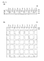
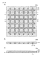
- Fig. 1 illustrates a separator 10, according to a first embodiment of the present invention.
- Fig. 1a is a sectional view of the separator 10
- Fig. 1b is a plan view of the separator 10.
- the separator 10 includes a first nanofiber layer 20 which has square openings and has a crisscross lattice structure when viewed from a plan view, a second nanofiber layer 30 which is disposed on one surface of the first nanofiber layer 20 and is thinner than the first nanofiber layer 20, and a third nanofiber layer 40 which is disposed on the other surface of the first nanofiber layer 20 and is thinner than the first nanofiber layer 20.
- the thickness of the first nanofiber layer 20 ranges from 7 ⁇ m to 30 ⁇ m (for example, 15 ⁇ m).
- the thickness of each of the second and third nanofiber layers 30 and 40 ranges from 1 ⁇ m to 5 ⁇ m (for example, 3 ⁇ m).
- the first nanofiber layer 20 When viewed from the plan view, the first nanofiber layer 20 has a plurality of openings O, a total area S2 of which is greater than a total area S1 of a lattice L.
- Each opening O has an average area ranging from 10 ⁇ m 2 to 200 ⁇ m 2 (for example, 50 ⁇ m 2 ).
- the thickness of the lattice L ranges from 1 ⁇ m to 10 ⁇ m (for example, 2 ⁇ m).
- the first nanofiber layer 20 is formed of first nanofibers produced by electrospinning. Each first nanofiber has an average diameter ranging from 30 nm to 3000nm (preferably, 800nm).
- the first nanofiber layer 20 is made of polymer material (for example, polyolefin).
- the second nanofiber layer 30 and the third nanofiber layer 40 are respectively formed by second nanofibers and third nanofibers which are produced by electrospinning.
- Each of the second and third nanofibers 30 and 40 has an average diameter ranging from 30 nm to 3000nm (preferably, 300nm).
- each of the second and third nanofibers 30 and 40 is made of polymer material (for example, polyolefin).
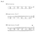
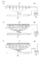
- Figs. 2 and 3 are views illustrating a method for manufacturing the separator according to the first embodiment of the present invention.
- Figs. 2a through 2c are sectional views showing a process of manufacturing the separator.
- Figs. 3a through 3c are sectional views illustrating the operation of an apparatus while manufacturing the separator.
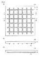
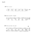
- Fig. 4 illustrates the construction of a collector 110 used in the separator manufacturing method according to the first embodiment.
- Fig. 4a is a bottom view of the collector 110
- Fig. 4b is a sectional view taken along line A1-A1 of Fig. 4a
- Fig. 4c is a sectional view taken along line A2-A2 of Fig. 4a .
- the separator 10 according to the first embodiment can be manufactured by successively carrying out a first process (refer to Fig. 2a ) of forming the first nanofiber layer 20 having a lattice shape, and a second process (refer to Figs. 2b and 2c ) of forming the second nanofiber layer 30, which is thinner than the first nanofiber layer 20, on one surface of the first nanofiber layer 20 and forming the third nanofiber layer 40, which is also thinner than the first nanofiber layer 20, on the other surface of the first nanofiber layer 20.
- a first process (refer to Fig. 2a ) of forming the first nanofiber layer 20 having a lattice shape
- a second process (refer to Figs. 2b and 2c ) of forming the second nanofiber layer 30, which is thinner than the first nanofiber layer 20, on one surface of the first nanofiber layer 20 and forming the third nanofiber layer 40, which is also thinner than the first nanofiber layer 20, on the other surface of the first nanofiber layer 20.
- the electrospinning apparatus 100 includes a collector electrode 114, a nozzle 122 which is disposed facing the collector electrode 114, a power supply 130 which applies high voltage between the collector electrode 114 and the nozzle 122, and a raw material tank (not shown) which stores polymer solution which is supplied to the nozzle 122.
- the collector electrode 114 comprises an electrode which has a lattice shape when viewed from the plan view and is disposed on a support 112 made of an insulation material. The support 112 and the collector electrode 114 form the collector 110.
- the nozzle 122 is oriented upwards and is installed on a nozzle block 120.
- An anode of the power supply 130 is connected to the collector electrode 114, and a cathode of the power supply 130 is connected to the nozzle block 120.
- the nozzle 122 discharges polymer solution and forms the lattice-shaped first nanofiber layer 20 on the collector 110.
- the second process is conducted using an electrospinning apparatus 200.
- the electrospinning apparatus 200 is a typical electrospinning apparatus, and a collector 210 comprises a planar electrode.
- the first nanofiber layer 20 is installed on the collector 210 of the electrospinning apparatus 200. Thereafter, with high voltage applied between the collector 210 and the nozzle 222, the nozzle 222 discharges polymer solution, thus forming the second nanofiber layer 30 on one surface of the first nanofiber layer 20 (refer to Fig. 2b ).
- the layered substance including the first nanofiber layer 20 and the second nanofiber layer 30 is turned upside down and is installed on the collector 210 of the electrospinning apparatus 200. Thereafter, while high voltage is applied between the collector 210 and the nozzle 222, the nozzle 222 discharges polymer solution, thus forming the third nanofiber layer 40 on the other surface of the first nanofiber layer 20 (refer to Fig. 2c ).
- the separator 10 according to the first embodiment can be manufactured.
- the separator 10 includes the first nanofiber layer 20 which has a lattice shape when viewed from the plan view, and the second and third nanofiber layers 30 and 40 which are thinner than the first nanofiber layer 20. Therefore, by virtue of the operation of the second nanofiber layer 30 and the third nanofiber layer 40, the separator 10 can have high insulation, high dendrite resistance and high ion conductivity.
- the separator 10 according to the first embodiment includes the first nanofiber layer 20 which has a lattice shape when viewed from the plan view, and the second and third nanofiber layers 30 and 40 which are thinner than the first nanofiber layer 20, it is possible that the mechanical strength of the separator 10 is satisfactorily enhanced merely by increasing the thickness of the lattice-shaped first nanofiber layer 20.
- the thickness of the first nanofiber layer 20 is increased, because the first nanofiber layer 20 has a lattice structure when viewed from the plan view, the flow of electrolyte can be satisfactorily maintained, thereby preventing the ion conductivity from being reduced.
- the separator 10 according to the first embodiment can have high insulation, high dendrite resistance, high ion conductivity and high mechanical strength.
- the separator 10 according to the first embodiment has sufficient mechanical strength despite having an appropriate thickness.
- each of the second and the third nanofiber layers 30 and 40 ranges from 1 ⁇ m to 5 ⁇ m, high insulation, high dendrite resistance and high ion conductivity can be ensured.
- the separator 10 according to the first embodiment is configured such that the first nanofiber layer 20 has the openings, the total area of which is greater than that of the lattice. Hence, the separator 10 can have high ion conductivity.
- the separator 10 according to the first embodiment can have high ion conductivity.
- the separator manufacturing method according to the first embodiment includes the first process and the second process which are successively carried out.
- the separator 10 according to the first embodiment that has high insulation, high dendrite resistance, high ion conductivity and high mechanical strength can be manufactured.
- the second nanofiber layer 30 is formed on one surface of the first nanofiber layer 20 by electrospinning while the third nanofiber layer 40 is formed on the other surface of the first nanofiber layer 20 by electrospinning. Therefore, the method of the present invention makes it possible to produce a high-quality separator in which high bonding strength among the first nanofiber layer 20, the second nanofiber layer 30 and the third nanofiber layer 40 can be ensured.
- Fig. 5 illustrates the construction of a collector 110a used in a method for manufacturing a separator, according to a second embodiment of the present invention.
- Fig. 5a is a bottom view of the collector 110a
- Fig. 5b is a sectional view taken along line A1-A1 of Fig. 5a
- Fig. 5c is a sectional view taken along line A2-A2 of Fig. 5a .
- the separator manufacturing method according to the second embodiment includes the same processes as those of the separator manufacturing method according to the first embodiment, but the construction of the collector used in the first process of the second embodiment is different from that of the first embodiment.
- the collector 110a used in the separator manufacturing method according to the second embodiment is configured such that a collector electrode 114 is embedded in an electrode body 118, which is equipotential with the nozzle 122, with an insulator 116 provided between the collector electrode 114 and the electrode body 118.
- the separator manufacturing method according to the second embodiment although the construction of the collector used during the first process is different from that of the first embodiment, the first process and the second process are successively conducted in the same manner as that of the separator manufacturing method according to the first embodiment, whereby a separator which has the above-mentioned construction and has high insulation, high dendrite resistance, high ion conductivity and high mechanical strength can be manufactured in the same manner as that of the first embodiment.
- the openings O of the separator have more reliably opened structures, compared to that of the separator manufactured by the separator manufacturing method according to the first embodiment.
- the separator manufacturing method according to the second embodiment has the same processes as those of the separator manufacturing method according to the first embodiment, other than the fact that the construction of the collector used during the first process differs between the first and second embodiments. Therefore, the separator manufacturing method according to the second embodiment can have effects corresponding to the effects of the separator manufacturing method according to the first embodiment.
- Fig. 6 illustrates a method for manufacturing a separator according to a third embodiment of the present invention.
- Figs. 6a through 6c are sectional views showing processes of manufacturing the separator.
- the separator manufacturing method according to the third embodiment basically includes the same processes as those of the separator manufacturing method according to the first embodiment, but the contents of the second process of the third embodiment are different from that of the first embodiment.
- a second nanofiber layer and a third nanofiber layer which are formed by electrospinning are prepared to be respectively used as the second nanofiber layer 32 and the third nanofiber layer 42.
- the second nanofiber layer 32 is attached to one surface of the first nanofiber layer 20
- the third nanofiber layer 42 is attached to the other surface of the first nanofiber layer 20.
- Adhesive may be used to embody the second process, pressure may be used, or heat and pressure may be used.
- the first process and the second process are successively conducted in the same manner as that of the separator manufacturing method according to the first embodiment, whereby a separator which has the above-mentioned construction and has high insulation, high dendrite resistance, high ion conductivity and high mechanical strength can be manufactured.
- the separator manufacturing method according to the third embodiment is able to increase productivity in a separator production.
- the separator manufacturing method according to the third embodiment has the same processes as those of the separator manufacturing method according to the first embodiment, other than the fact that the contents of the second process differ between the first and second embodiments. Therefore, the separator manufacturing method according to the third embodiment can have effects corresponding to the effects of the separator manufacturing method according to the first embodiment.
- the upward discharge type electrospinning apparatus having the upward nozzle has been illustrated as being used in the separator manufacturing method of the present invention, the present invention is not limited to this structure.
- a downward discharge type electrospinning apparatus having a downward nozzle or a horizontal discharge type electrospinning apparatus having a horizontal nozzle may be used in the separator manufacturing method of the present invention.
Landscapes
- Engineering & Computer Science (AREA)
- Chemical & Material Sciences (AREA)
- Chemical Kinetics & Catalysis (AREA)
- Electrochemistry (AREA)
- General Chemical & Material Sciences (AREA)
- Power Engineering (AREA)
- Microelectronics & Electronic Packaging (AREA)
- Manufacturing & Machinery (AREA)
- Cell Separators (AREA)
- Electric Double-Layer Capacitors Or The Like (AREA)
- Nonwoven Fabrics (AREA)
- Spinning Methods And Devices For Manufacturing Artificial Fibers (AREA)
Applications Claiming Priority (3)
| Application Number | Priority Date | Filing Date | Title |
|---|---|---|---|
| JP2011061841A JP5798346B2 (ja) | 2011-03-20 | 2011-03-20 | セパレーターの製造方法 |
| KR1020110125760A KR101154210B1 (ko) | 2011-03-20 | 2011-11-29 | 세퍼레이터의 제조 방법 |
| PCT/KR2012/000853 WO2012128474A2 (fr) | 2011-03-20 | 2012-02-06 | Séparateur et procédé pour fabriquer un séparateur |
Publications (2)
| Publication Number | Publication Date |
|---|---|
| EP2642556A2 true EP2642556A2 (fr) | 2013-09-25 |
| EP2642556A4 EP2642556A4 (fr) | 2014-08-20 |
Family
ID=46688826
Family Applications (1)
| Application Number | Title | Priority Date | Filing Date |
|---|---|---|---|
| EP12761231.5A Withdrawn EP2642556A4 (fr) | 2011-03-20 | 2012-02-06 | Séparateur et procédé pour fabriquer un séparateur |
Country Status (6)
| Country | Link |
|---|---|
| US (1) | US9177729B2 (fr) |
| EP (1) | EP2642556A4 (fr) |
| JP (1) | JP5798346B2 (fr) |
| KR (1) | KR101154210B1 (fr) |
| CN (1) | CN103314466B (fr) |
| WO (1) | WO2012128474A2 (fr) |
Cited By (4)
| Publication number | Priority date | Publication date | Assignee | Title |
|---|---|---|---|---|
| WO2015138903A1 (fr) * | 2014-03-14 | 2015-09-17 | Altria Client Services Inc. | Procédé et appareil d'enrobage de partie de produit |
| US9756875B2 (en) | 2010-08-05 | 2017-09-12 | Altria Client Services Llc | Composite smokeless tobacco products, systems, and methods |
| US9814261B2 (en) | 2010-08-05 | 2017-11-14 | Altria Client Services Llc | Fabric having tobacco entangled with structural fibers |
| US9896228B2 (en) | 2014-03-14 | 2018-02-20 | Altria Client Services Llc | Polymer encased smokeless tobacco products |
Families Citing this family (12)
| Publication number | Priority date | Publication date | Assignee | Title |
|---|---|---|---|---|
| KR101705305B1 (ko) * | 2012-10-22 | 2017-02-09 | 주식회사 엘지화학 | 균일한 기공 배열을 갖는 다공성 분리막 및 이를 포함하는 이차전지 |
| CN104104468B (zh) * | 2013-04-03 | 2018-09-11 | 电信科学技术研究院 | 一种上下行配置信息传输方法和设备 |
| JP6234546B2 (ja) * | 2014-03-14 | 2017-11-22 | 東京応化工業株式会社 | 二次電池用多孔質セパレータおよびそれを用いた二次電池 |
| US20170149552A1 (en) * | 2014-06-17 | 2017-05-25 | Nokia Solutions And Networks Oy | Method for Informing Switching Patterns of Half Duplex Communications in LTE |
| KR101821049B1 (ko) | 2016-07-15 | 2018-01-23 | 한국과학기술원 | 1차원의 고분자 나노섬유들이 준정렬된 그리드 형상으로 직교하여 적층되어 기공 분포 및 기공 크기가 제어된 3차원 고분자 나노섬유 멤브레인 및 그 제조방법 |
| KR102157935B1 (ko) * | 2018-01-10 | 2020-09-18 | 주식회사 엘지화학 | 강화 분리막 제조방법, 이에 의하여 제조된 강화 분리막 및 레독스 흐름 전지 |
| JP7395512B2 (ja) | 2018-06-08 | 2023-12-11 | アセンド・パフォーマンス・マテリアルズ・オペレーションズ・リミテッド・ライアビリティ・カンパニー | 調節可能なナノファイバー不織布製品 |
| KR102145670B1 (ko) * | 2018-10-31 | 2020-08-19 | 전주대학교 산학협력단 | 도체와이어를 이용한 고분자 나노물질의 균일방사를 위한 전기방사장치 |
| WO2020210695A1 (fr) | 2019-04-12 | 2020-10-15 | Ascend Performance Materials Operations Llc | Structures multicouches non tissées ayant des couches de nanofibres |
| JP7276970B2 (ja) * | 2019-05-22 | 2023-05-18 | エルジー エナジー ソリューション リミテッド | リチウム二次電池用分離膜積層体、これを含む電極組立体およびリチウム二次電池 |
| KR102834337B1 (ko) * | 2019-05-22 | 2025-07-15 | 주식회사 엘지에너지솔루션 | 리튬 이차 전지용 분리막 적층체, 이를 포함하는 전극 조립체 및 리튬 이차 전지 |
| CN112332020B (zh) * | 2020-10-31 | 2022-06-14 | 华南理工大学 | 一种跨尺度微纳纤维素锂离子电池隔膜及其制备方法 |
Family Cites Families (20)
| Publication number | Priority date | Publication date | Assignee | Title |
|---|---|---|---|---|
| JP3002830B2 (ja) * | 1990-02-02 | 2000-01-24 | 日本バイリーン株式会社 | 電池用セパレータ及びその製造方法 |
| JPH0948533A (ja) * | 1995-05-26 | 1997-02-18 | Minolta Co Ltd | ベルト蛇行補正装置 |
| JP3644764B2 (ja) | 1996-06-28 | 2005-05-11 | 日本バイリーン株式会社 | アルカリ電池用セパレータ |
| JP3547071B2 (ja) * | 1997-09-26 | 2004-07-28 | 小松フォークリフト株式会社 | 産業車両のlpgボンベ脱着容易化装置 |
| US6277514B1 (en) * | 1998-12-17 | 2001-08-21 | Moltech Corporation | Protective coating for separators for electrochemical cells |
| US6194098B1 (en) * | 1998-12-17 | 2001-02-27 | Moltech Corporation | Protective coating for separators for electrochemical cells |
| TWI241732B (en) * | 2002-09-25 | 2005-10-11 | E I Du Pont Canada Company | Mesh reinforced fuel cell separator plate |
| US20050208383A1 (en) * | 2004-03-19 | 2005-09-22 | Hiroki Totsuka | Electronic component separator and method for producing the same |
| JP4803984B2 (ja) * | 2004-09-22 | 2011-10-26 | 帝人株式会社 | リチウムイオン二次電池用セパレータおよびその製造方法とリチウムイオン二次電池 |
| KR101093590B1 (ko) * | 2004-11-30 | 2011-12-15 | 에스케이이노베이션 주식회사 | 다층형 고분자 막을 이용한 리튬 고분자 전지 및 그의제조방법 |
| JP4734912B2 (ja) * | 2004-12-17 | 2011-07-27 | 日産自動車株式会社 | リチウムイオン電池およびその製造方法 |
| JP5191091B2 (ja) * | 2005-08-09 | 2013-04-24 | 日本バイリーン株式会社 | リチウムイオン二次電池用セパレータ及びリチウムイオン二次電池 |
| DE102006049746A1 (de) * | 2006-10-21 | 2008-04-24 | Dilo Trading Ag | Separator für Lithium-Polymer Batterien und Verfahren zur Herstellung derselben |
| US20080145750A1 (en) * | 2006-12-18 | 2008-06-19 | Szu-Nan Yang | Electricity supply system |
| KR101460640B1 (ko) * | 2007-07-06 | 2014-12-02 | 소니 가부시끼가이샤 | 세퍼레이터, 세퍼레이터를 이용한 전지, 및 세퍼레이터를제조하는 방법 |
| EP2202764A4 (fr) * | 2007-10-18 | 2018-03-28 | Kuraray Co., Ltd. | Stratifié, séparateur pour condensateur, et condensateur |
| JP5049092B2 (ja) | 2007-10-18 | 2012-10-17 | 株式会社クラレ | キャパシタ用セパレータおよびキャパシタ |
| JP5396399B2 (ja) * | 2008-11-11 | 2014-01-22 | 日本板硝子株式会社 | 密閉型鉛蓄電池用セパレータ及び密閉型鉛蓄電池 |
| WO2011035190A1 (fr) * | 2009-09-18 | 2011-03-24 | Nano Terra Inc. | Fibres de polyoléfines utilisées comme séparateurs de batteries et leurs procédés de fabrication et d'utilisation |
| CN102544642A (zh) * | 2010-12-13 | 2012-07-04 | 依诺特生物能量控股公司 | 隔离膜、隔离膜制造方法及有机电池 |
-
2011
- 2011-03-20 JP JP2011061841A patent/JP5798346B2/ja active Active
- 2011-11-29 KR KR1020110125760A patent/KR101154210B1/ko active Active
-
2012
- 2012-02-06 US US13/977,711 patent/US9177729B2/en active Active
- 2012-02-06 EP EP12761231.5A patent/EP2642556A4/fr not_active Withdrawn
- 2012-02-06 WO PCT/KR2012/000853 patent/WO2012128474A2/fr not_active Ceased
- 2012-02-06 CN CN201280005469.3A patent/CN103314466B/zh not_active Expired - Fee Related
Cited By (15)
| Publication number | Priority date | Publication date | Assignee | Title |
|---|---|---|---|---|
| US10448669B2 (en) | 2010-08-05 | 2019-10-22 | Altria Client Services Llc | Non-tobacco product having polyurethane structural fibers |
| US9756875B2 (en) | 2010-08-05 | 2017-09-12 | Altria Client Services Llc | Composite smokeless tobacco products, systems, and methods |
| US9814261B2 (en) | 2010-08-05 | 2017-11-14 | Altria Client Services Llc | Fabric having tobacco entangled with structural fibers |
| US12150476B2 (en) | 2010-08-05 | 2024-11-26 | Altria Client Services Llc | Fabric having tobacco entangled with structural fibers |
| US11540560B2 (en) | 2010-08-05 | 2023-01-03 | Altria Client Services Llc | Fabric having tobacco entangled with structural fibers |
| US10736354B2 (en) | 2010-08-05 | 2020-08-11 | Altria Client Services Llc | Fabric having tobacco entangled with structural fibers |
| US9896228B2 (en) | 2014-03-14 | 2018-02-20 | Altria Client Services Llc | Polymer encased smokeless tobacco products |
| EP3597052A1 (fr) * | 2014-03-14 | 2020-01-22 | Altria Client Services LLC | Procédé et appareil d'enrobage de partie de produit |
| US10384816B2 (en) | 2014-03-14 | 2019-08-20 | Altria Client Services Llc | Polymer encased smokeless tobacco products |
| US10875051B2 (en) | 2014-03-14 | 2020-12-29 | Altria Client Services Llc | Product portion enrobing process and apparatus |
| US11198151B2 (en) | 2014-03-14 | 2021-12-14 | Altria Client Services Llc | Polymer encased smokeless tobacco products |
| US10239089B2 (en) | 2014-03-14 | 2019-03-26 | Altria Client Services Llc | Product portion enrobing process and apparatus |
| US11731162B2 (en) | 2014-03-14 | 2023-08-22 | Altria Client Services Llc | Polymer encased smokeless tobacco products |
| WO2015138903A1 (fr) * | 2014-03-14 | 2015-09-17 | Altria Client Services Inc. | Procédé et appareil d'enrobage de partie de produit |
| US12151260B2 (en) | 2014-03-14 | 2024-11-26 | Altria Client Services Llc | Polymer encased smokeless tobacco products |
Also Published As
| Publication number | Publication date |
|---|---|
| CN103314466A (zh) | 2013-09-18 |
| JP5798346B2 (ja) | 2015-10-21 |
| JP2012199037A (ja) | 2012-10-18 |
| WO2012128474A2 (fr) | 2012-09-27 |
| KR101154210B1 (ko) | 2012-06-18 |
| US9177729B2 (en) | 2015-11-03 |
| US20140004405A1 (en) | 2014-01-02 |
| EP2642556A4 (fr) | 2014-08-20 |
| CN103314466B (zh) | 2015-11-25 |
| WO2012128474A3 (fr) | 2012-11-22 |
Similar Documents
| Publication | Publication Date | Title |
|---|---|---|
| US9177729B2 (en) | Separator and method for manufacturing separator | |
| EP2693529B1 (fr) | Mat de fibres de renforcement d'une plaque de batterie | |
| JP2014041817A5 (fr) | ||
| KR20240108534A (ko) | 탄소를 도입한 개선된 납축전지 분리기 | |
| US10026965B2 (en) | Method for manufacturing electrode structure for flexible energy storage device, electrode structure manufactured thereby, and energy storage device including same | |
| US9299967B2 (en) | Secondary battery comprising insulator | |
| KR102429448B1 (ko) | 세퍼레이터 및 알루미늄 전해 컨덴서 | |
| US10581046B2 (en) | Laminar textile material for a battery electrode | |
| US20180159122A1 (en) | Conductive mat for battery electrode plate reinforcement and methods of use therefor | |
| US20060210874A1 (en) | Electrode for an electrochemical cell, electrode coil, electrochemical cell, and production method | |
| CN113165868A (zh) | 用于堆叠体沉积的增强的纳米线结构 | |
| KR102404190B1 (ko) | 축전 디바이스용 세퍼레이터 및 상기 세퍼레이터를 사용한 축전 디바이스 | |
| US9637825B2 (en) | High-temperature long lifespan electrode for electric dual layer capacitor and method of manufacturing the same | |
| CN100557868C (zh) | 集电极、电池电极基底、及其生产方法 | |
| KR102096411B1 (ko) | 절연층과 상이한 방법으로 형성된 접착층을 포함하는 전극-분리막 단위체 및 이의 제조방법 | |
| CN105322130A (zh) | 极片及其制造方法 | |
| KR101746876B1 (ko) | 전극판, 이를 포함하는 이차전지 및 전극판의 제조방법 | |
| JP5191091B2 (ja) | リチウムイオン二次電池用セパレータ及びリチウムイオン二次電池 | |
| KR20140069850A (ko) | 고에너지밀도의 리튬이온배터리 및 이의 제조방법 | |
| JPWO2020080421A1 (ja) | 鉛蓄電池 | |
| JP2014220042A (ja) | 電極、電極の製造方法及び電池 | |
| US20140349194A1 (en) | Separator and method for manufacturing the separator | |
| US20150270518A1 (en) | Battery | |
| US9922774B2 (en) | High density electrode for electric dual layer capacitor and method of manufacturing the same | |
| JPWO2012101903A1 (ja) | 固体電解コンデンサ |
Legal Events
| Date | Code | Title | Description |
|---|---|---|---|
| PUAI | Public reference made under article 153(3) epc to a published international application that has entered the european phase |
Free format text: ORIGINAL CODE: 0009012 |
|
| 17P | Request for examination filed |
Effective date: 20130620 |
|
| AK | Designated contracting states |
Kind code of ref document: A2 Designated state(s): AL AT BE BG CH CY CZ DE DK EE ES FI FR GB GR HR HU IE IS IT LI LT LU LV MC MK MT NL NO PL PT RO RS SE SI SK SM TR |
|
| DAX | Request for extension of the european patent (deleted) | ||
| A4 | Supplementary search report drawn up and despatched |
Effective date: 20140722 |
|
| RIC1 | Information provided on ipc code assigned before grant |
Ipc: H01M 2/16 20060101AFI20140716BHEP |
|
| 17Q | First examination report despatched |
Effective date: 20150623 |
|
| GRAP | Despatch of communication of intention to grant a patent |
Free format text: ORIGINAL CODE: EPIDOSNIGR1 |
|
| RIC1 | Information provided on ipc code assigned before grant |
Ipc: H01G 9/02 20060101AFI20160316BHEP Ipc: H01M 2/16 20060101ALI20160316BHEP Ipc: H01M 2/04 20060101ALI20160316BHEP Ipc: H01M 2/14 20060101ALI20160316BHEP |
|
| INTG | Intention to grant announced |
Effective date: 20160404 |
|
| STAA | Information on the status of an ep patent application or granted ep patent |
Free format text: STATUS: THE APPLICATION IS DEEMED TO BE WITHDRAWN |
|
| 18D | Application deemed to be withdrawn |
Effective date: 20160817 |