EP2642832A1 - Électrode à plasma pour une torche à plasma d'arc avec extrémité d'électrode échangeable - Google Patents
Électrode à plasma pour une torche à plasma d'arc avec extrémité d'électrode échangeable Download PDFInfo
- Publication number
- EP2642832A1 EP2642832A1 EP12002077.1A EP12002077A EP2642832A1 EP 2642832 A1 EP2642832 A1 EP 2642832A1 EP 12002077 A EP12002077 A EP 12002077A EP 2642832 A1 EP2642832 A1 EP 2642832A1
- Authority
- EP
- European Patent Office
- Prior art keywords
- electrode
- plasma
- plasma electrode
- electrode tip
- tip
- Prior art date
- Legal status (The legal status is an assumption and is not a legal conclusion. Google has not performed a legal analysis and makes no representation as to the accuracy of the status listed.)
- Withdrawn
Links
- 238000001816 cooling Methods 0.000 claims abstract description 8
- 239000011343 solid material Substances 0.000 claims abstract description 3
- 239000000463 material Substances 0.000 claims description 24
- 239000002184 metal Substances 0.000 claims 1
- 238000007789 sealing Methods 0.000 description 6
- BQCADISMDOOEFD-UHFFFAOYSA-N Silver Chemical compound [Ag] BQCADISMDOOEFD-UHFFFAOYSA-N 0.000 description 5
- 229910052709 silver Inorganic materials 0.000 description 5
- 239000004332 silver Substances 0.000 description 5
- 239000010949 copper Substances 0.000 description 3
- 229910052735 hafnium Inorganic materials 0.000 description 3
- VBJZVLUMGGDVMO-UHFFFAOYSA-N hafnium atom Chemical compound [Hf] VBJZVLUMGGDVMO-UHFFFAOYSA-N 0.000 description 3
- 229910001316 Ag alloy Inorganic materials 0.000 description 2
- 229910017944 Ag—Cu Inorganic materials 0.000 description 2
- 229910017770 Cu—Ag Inorganic materials 0.000 description 2
- 229910001128 Sn alloy Inorganic materials 0.000 description 2
- QCWXUUIWCKQGHC-UHFFFAOYSA-N Zirconium Chemical compound [Zr] QCWXUUIWCKQGHC-UHFFFAOYSA-N 0.000 description 2
- 239000003795 chemical substances by application Substances 0.000 description 2
- KUNSUQLRTQLHQQ-UHFFFAOYSA-N copper tin Chemical compound [Cu].[Sn] KUNSUQLRTQLHQQ-UHFFFAOYSA-N 0.000 description 2
- 229910052726 zirconium Inorganic materials 0.000 description 2
- 229910000906 Bronze Inorganic materials 0.000 description 1
- RYGMFSIKBFXOCR-UHFFFAOYSA-N Copper Chemical compound [Cu] RYGMFSIKBFXOCR-UHFFFAOYSA-N 0.000 description 1
- 229910000881 Cu alloy Inorganic materials 0.000 description 1
- 230000004308 accommodation Effects 0.000 description 1
- 239000010974 bronze Substances 0.000 description 1
- 239000002131 composite material Substances 0.000 description 1
- 150000001875 compounds Chemical class 0.000 description 1
- 239000004020 conductor Substances 0.000 description 1
- 239000002826 coolant Substances 0.000 description 1
- 229910052802 copper Inorganic materials 0.000 description 1
- 230000003628 erosive effect Effects 0.000 description 1
- 238000010304 firing Methods 0.000 description 1
- 230000008023 solidification Effects 0.000 description 1
- 238000007711 solidification Methods 0.000 description 1
Images



Classifications
-
- H—ELECTRICITY
- H05—ELECTRIC TECHNIQUES NOT OTHERWISE PROVIDED FOR
- H05H—PLASMA TECHNIQUE; PRODUCTION OF ACCELERATED ELECTRICALLY-CHARGED PARTICLES OR OF NEUTRONS; PRODUCTION OR ACCELERATION OF NEUTRAL MOLECULAR OR ATOMIC BEAMS
- H05H1/00—Generating plasma; Handling plasma
- H05H1/24—Generating plasma
- H05H1/26—Plasma torches
- H05H1/32—Plasma torches using an arc
- H05H1/34—Details, e.g. electrodes, nozzles
- H05H1/3436—Hollow cathodes with internal coolant flow
-
- H—ELECTRICITY
- H05—ELECTRIC TECHNIQUES NOT OTHERWISE PROVIDED FOR
- H05H—PLASMA TECHNIQUE; PRODUCTION OF ACCELERATED ELECTRICALLY-CHARGED PARTICLES OR OF NEUTRONS; PRODUCTION OR ACCELERATION OF NEUTRAL MOLECULAR OR ATOMIC BEAMS
- H05H1/00—Generating plasma; Handling plasma
- H05H1/24—Generating plasma
- H05H1/26—Plasma torches
- H05H1/28—Cooling arrangements
-
- H—ELECTRICITY
- H05—ELECTRIC TECHNIQUES NOT OTHERWISE PROVIDED FOR
- H05H—PLASMA TECHNIQUE; PRODUCTION OF ACCELERATED ELECTRICALLY-CHARGED PARTICLES OR OF NEUTRONS; PRODUCTION OR ACCELERATION OF NEUTRAL MOLECULAR OR ATOMIC BEAMS
- H05H1/00—Generating plasma; Handling plasma
- H05H1/24—Generating plasma
- H05H1/26—Plasma torches
- H05H1/32—Plasma torches using an arc
- H05H1/34—Details, e.g. electrodes, nozzles
- H05H1/3423—Connecting means, e.g. electrical connecting means or fluid connections
-
- H—ELECTRICITY
- H05—ELECTRIC TECHNIQUES NOT OTHERWISE PROVIDED FOR
- H05H—PLASMA TECHNIQUE; PRODUCTION OF ACCELERATED ELECTRICALLY-CHARGED PARTICLES OR OF NEUTRONS; PRODUCTION OR ACCELERATION OF NEUTRAL MOLECULAR OR ATOMIC BEAMS
- H05H1/00—Generating plasma; Handling plasma
- H05H1/24—Generating plasma
- H05H1/26—Plasma torches
- H05H1/32—Plasma torches using an arc
- H05H1/34—Details, e.g. electrodes, nozzles
- H05H1/3442—Cathodes with inserted tip
Definitions
- the invention relates to a plasma electrode for a plasma arc burner, comprising an electrode body which has at least one electrode core arranged on the electrode tip.
- Such plasma electrodes for use in plasma arc torches have become known in various embodiments.
- the JP 2007-180028 A or the EP 1 765 046 B1 directed.
- the wear of the plasma electrode during operation is considerable.
- the electrode core inserted into the front of the plasma electrode in the region of the electrode tip in a bore produces the plasma arc at temperatures in the range between 1000 to 2000 degrees Celsius and consists of an electrically conductive, highly emissive material, e.g. Hafnium or zirconium.
- the electrode tip is heavily stressed by the high firing temperatures.
- material erosion occurs on the electrode core which deposit as splashes of material on the electrode tip and its surroundings, which leads to undesirable wear and a limitation of the service life.
- the EP 1 633 172 A2 Proposes to keep the electrode core, which consists of a hafnium material, in a silver insert on the electrode tip. This insert (see FIG. 7 ) is soldered into the front area of the electrode tip.
- the invention is therefore based on the object, a plasma electrode for a plasma arc burner of the type mentioned in such a way that a more easy and cost-effective replacement of the electrode is possible during wear.
- the invention is characterized by the technical teaching of claim 1.
- the plasma electrode is formed at least in two parts and at least consists of the front electrode tip and a rear fastening part and that the electrode tip is replaceably held on the fastening part.
- the invention provides for a multi-part plasma electrode, wherein the simpler description is based in the following description of only two parts of this plasma electrode, although the plasma electrode can also consist of more than two parts.
- the description of a bipartite plasma electrode is therefore not intended to limit the scope of the invention.
- An essential feature of the invention is that in a two-part design of the plasma electrode is now possible to solve the front part of the rear part, because these two parts are preferably releasably connected to each other.
- the front electrode tip can be removed with the electrode core inserted there from the rear attachment part of the plasma electrode, provided that wear on the electrode tip occurs.
- the detachable connection between the two parts of the plasma electrode is designed as a screw connection, as a plug-in connection or as a combined screw-type connector.
- the screw consists of two interlocking threads.
- an internal thread can be arranged, which can be screwed into an associated external thread in the region of the rear attachment part of the plasma electrode.
- the electrode tip has an external thread which can be screwed onto an associated internal thread of the rear attachment part of the plasma electrode.
- a plug connection is used, such.
- a bayonet connector that can be solved and fixed by a rotary-plug movement.
- the detachable connection between the two parts of the plasma electrode consists of a sealed flange, wherein two oppositely disposed flanges on the two parts associated with each other and are liquid-tightly sealed from each other.
- a flange connection is secured by a union nut in connection with a thread on the opposite part.
- clamping connections are also provided.
- Such a clamp connection is z. B. a flange, with two sealingly opposite and abutting flanges, of a Eccentric clamping ring to be held sealingly on mutual contact pressure.
- the rear fixing part of the plasma electrode is made of a low-cost copper material or a copper alloy
- the front part of the electrode tip, which is subject to wear is made of a silver material or a silver alloy.
- the electrode tip is made of high-quality silver or a silver alloy.
- silver as a highly conductive material has been given by way of example only. Of course, other highly conductive, readily processable materials can be used which have the properties of silver. In particular tin alloys come into consideration or copper-tin alloys (bronze).
- the abovementioned materials can be used in the same abovementioned material pairings as have been specified above using the example of the material Ag.
- the invention is not limited to hollow cylindrical plasma electrodes, in the interior of which a cooling tube is arranged, with which a cooling medium-preferably water-introduced into the interior of the plasma electrode, is diverted at the front end in the vicinity of the electrode tip, and then out again the plasma electrode is led out.
- a cooling medium-preferably water-introduced into the interior of the plasma electrode is diverted at the front end in the vicinity of the electrode tip, and then out again the plasma electrode is led out.
- the invention also claims uncooled hollow cylindrical or also consisting of solid material plasma electrodes, which are at least two parts and the front part subject to wear is easily detachably connected to the rear part.
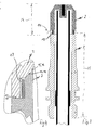
- plasma electrode 1 is constructed in two parts and consists of the front, replaceable electrode tip 2 and a rear attachment part 3, which is centered with a radially outer mounting flange 7 on the inside of an electrode body not shown in detail and with a thread 8 in a more such electrode body can be screwed.
- the entire plasma electrode 1 can also be plugged sealed into an electrode body, not shown.
- a cooling tube 6 is arranged centrally, which engages with its front end in a receiving space 5 in the region of the electrode tip 2.
- an electrode core 4 is introduced from a highly-emissive material, such as. A hafnium or zirconium material.
- the cooling of the plasma electrode takes place in such a way that a coolant flow is introduced into the interior 10 of the cooling tube 6, which is deflected in the region of the receiving space 5 in the electrode tip 2 and is then recirculated via the radially outer inner bore 9.
- connection portion 11 of the detachable connection consists of a screw thread.
- the electrode tip 2 on a vertical flange on an external thread which in an associated internal thread a likewise integrally formed on the fastening part 3 flange attacks.
- a screw thread 12 is formed.
- opposing and rectified conical surfaces 13, 14 are arranged on associated flanges of the electrode tip 2 and the fastening part 3 and that further engages a preferably encircling annular flange 15 on the fastening part 3 in an associated annular groove 16 and there centered.
- FIG. 3 shows the composite structure of in FIG. 1 in the disassembled state shown plasma electrode, where it can be seen that the front, replaceable electrode tip 2 has a relatively short length 24 which is many times shorter than comparatively the non-replaceable attachment member 3 with a much greater length 25th
- the aspect ratios of these two lengths 24, 25 can range from 1: 1 to 1: 6.
- the electrode tip 2 is easily detachably mounted on the electrode-side fixing part 3 and therefore is easily replaceable when it is worn. It is kept short to keep material consumption low during replacement.
- FIGS. 5 to 8 show the kinematic reversal of a numeral 12 in the FIGS. 1 to 4 shown screw thread.
- the screw thread 12 consists of a arranged on the inside of the electrode tip 2 internal thread, which is screwed into an associated, radially outwardly directed external thread on the mounting part 3.
- the threaded screw connection is sealed by a sealing ring 19 liquid-tight.
- FIGS. 7 and 8 show another embodiment of the screw, and the rest, that in the area of the electrode tip 2 also a key surface 20 may be provided for the attack of a suitable tool with which the electrode tip 2 can be unscrewed from the mounting part 3.
- an external thread is arranged on the rear side of the electrode tip 2, which cooperates with an internal thread in the interior of the fastening part 3 and the entire threaded screw connection is sealed liquid-tight by a sealing ring 19 which is inserted in an associated annular groove 23 on the vertical flange of the electrode tip 2 ,
- the external thread 21 on the electrode tip 2 thus cooperates with the internal thread 22 on the fastening part 3 as a screw thread 12.
- FIGS. 9 to 12 show as a further embodiment, a plasma electrode in which the sealing ring 19 is integrally formed in the region of an outwardly open annular groove 23 at the foot of the vertical flange in the fastening part 3.
- the electrode tip 2 has an internal thread 22, which with the associated external thread 21 results in the sealed screw connection in the region of the connection part 11.
- FIGS. 11 and 12 show the in FIGS. 9 to 10 Threaded connection shown in the screwed state.
Landscapes
- Physics & Mathematics (AREA)
- Engineering & Computer Science (AREA)
- Plasma & Fusion (AREA)
- Spectroscopy & Molecular Physics (AREA)
- Plasma Technology (AREA)
- Arc Welding In General (AREA)
Priority Applications (4)
| Application Number | Priority Date | Filing Date | Title |
|---|---|---|---|
| EP12002077.1A EP2642832A1 (fr) | 2012-03-23 | 2012-03-23 | Électrode à plasma pour une torche à plasma d'arc avec extrémité d'électrode échangeable |
| EP13714852.4A EP2829162B1 (fr) | 2012-03-23 | 2013-03-22 | Électrode à plasma pour une torche à plasma d'arc avec extrémité d'électrode échangeable |
| US14/361,903 US9736916B2 (en) | 2012-03-23 | 2013-03-22 | Plasma electrode for a plasma arc torch with replaceable electrode tip |
| PCT/EP2013/000876 WO2013139484A1 (fr) | 2012-03-23 | 2013-03-22 | Électrode à plasma pour torche à plasma à arc transféré à embout d'électrode interchangeable |
Applications Claiming Priority (1)
| Application Number | Priority Date | Filing Date | Title |
|---|---|---|---|
| EP12002077.1A EP2642832A1 (fr) | 2012-03-23 | 2012-03-23 | Électrode à plasma pour une torche à plasma d'arc avec extrémité d'électrode échangeable |
Publications (1)
| Publication Number | Publication Date |
|---|---|
| EP2642832A1 true EP2642832A1 (fr) | 2013-09-25 |
Family
ID=48050654
Family Applications (2)
| Application Number | Title | Priority Date | Filing Date |
|---|---|---|---|
| EP12002077.1A Withdrawn EP2642832A1 (fr) | 2012-03-23 | 2012-03-23 | Électrode à plasma pour une torche à plasma d'arc avec extrémité d'électrode échangeable |
| EP13714852.4A Not-in-force EP2829162B1 (fr) | 2012-03-23 | 2013-03-22 | Électrode à plasma pour une torche à plasma d'arc avec extrémité d'électrode échangeable |
Family Applications After (1)
| Application Number | Title | Priority Date | Filing Date |
|---|---|---|---|
| EP13714852.4A Not-in-force EP2829162B1 (fr) | 2012-03-23 | 2013-03-22 | Électrode à plasma pour une torche à plasma d'arc avec extrémité d'électrode échangeable |
Country Status (3)
| Country | Link |
|---|---|
| US (1) | US9736916B2 (fr) |
| EP (2) | EP2642832A1 (fr) |
| WO (1) | WO2013139484A1 (fr) |
Cited By (1)
| Publication number | Priority date | Publication date | Assignee | Title |
|---|---|---|---|---|
| CZ308703B6 (cs) * | 2020-02-05 | 2021-03-03 | B&Bartoni, spol. s r.o. | Sestava elektrody pro plazmový obloukový hořák se zlepšeným přenosem elektrického proudu |
Families Citing this family (2)
| Publication number | Priority date | Publication date | Assignee | Title |
|---|---|---|---|---|
| CN109079294B (zh) * | 2018-10-31 | 2023-08-11 | 浙江巨化装备制造有限公司 | 全自动管板焊机枪头连续自动钨棒更换装置及更换方法 |
| EP3949695A1 (fr) * | 2019-04-04 | 2022-02-09 | Hypertherm, INC. | Consommables à longueur ajustable pour chalumeau à plasma refroidi par liquide |
Citations (7)
| Publication number | Priority date | Publication date | Assignee | Title |
|---|---|---|---|---|
| US5440094A (en) * | 1994-04-07 | 1995-08-08 | Douglas G. Carroll | Plasma arc torch with removable anode ring |
| US6114650A (en) * | 1998-08-12 | 2000-09-05 | The Esab Group, Inc. | Electrode for plasma arc torch and method of making same |
| EP1633172A2 (fr) | 2004-09-03 | 2006-03-08 | The Esab Group, Inc. | Electrode et support d'électrode avec raccord fileté |
| JP2007180028A (ja) | 2005-12-21 | 2007-07-12 | Esab Group Inc | プラズマアークトーチ、並びにプラズマアークトーチの組立及び分解方法 |
| EP1765046B1 (fr) | 2005-09-07 | 2010-08-25 | Hypertherm, Inc. | Electrode pour torche à plasma avec configurations ameliorées de pièce insérée |
| US20110240609A1 (en) * | 2008-12-18 | 2011-10-06 | Katrin Jehnert | Electrode for a Plasma Torch |
| EP2408274A2 (fr) | 2010-07-16 | 2012-01-18 | Hypertherm, Inc. | Régulation de l'écoulement d'une torche au moyen des propriétés de la buse |
Family Cites Families (5)
| Publication number | Priority date | Publication date | Assignee | Title |
|---|---|---|---|---|
| US5216221A (en) * | 1992-01-17 | 1993-06-01 | Esab Welding Products, Inc. | Plasma arc torch power disabling mechanism |
| US6498316B1 (en) * | 1999-10-25 | 2002-12-24 | Thermal Dynamics Corporation | Plasma torch and method for underwater cutting |
| US9662747B2 (en) * | 2006-09-13 | 2017-05-30 | Hypertherm, Inc. | Composite consumables for a plasma arc torch |
| DE102009016932B4 (de) * | 2009-04-08 | 2013-06-20 | Kjellberg Finsterwalde Plasma Und Maschinen Gmbh | Kühlrohre und Elektrodenaufnahme für einen Lichtbogenplasmabrenner sowie Anordnungen aus denselben und Lichtbogenplasmabrenner mit denselben |
| US9211603B2 (en) * | 2012-01-31 | 2015-12-15 | The Esab Group, Inc. | Plasma gouging torch and angled nozzle therefor |
-
2012
- 2012-03-23 EP EP12002077.1A patent/EP2642832A1/fr not_active Withdrawn
-
2013
- 2013-03-22 WO PCT/EP2013/000876 patent/WO2013139484A1/fr not_active Ceased
- 2013-03-22 US US14/361,903 patent/US9736916B2/en not_active Expired - Fee Related
- 2013-03-22 EP EP13714852.4A patent/EP2829162B1/fr not_active Not-in-force
Patent Citations (8)
| Publication number | Priority date | Publication date | Assignee | Title |
|---|---|---|---|---|
| US5440094A (en) * | 1994-04-07 | 1995-08-08 | Douglas G. Carroll | Plasma arc torch with removable anode ring |
| US6114650A (en) * | 1998-08-12 | 2000-09-05 | The Esab Group, Inc. | Electrode for plasma arc torch and method of making same |
| EP1633172A2 (fr) | 2004-09-03 | 2006-03-08 | The Esab Group, Inc. | Electrode et support d'électrode avec raccord fileté |
| US20060049150A1 (en) * | 2004-09-03 | 2006-03-09 | The Esab Group, Inc. | Electrode and electrode holder with threaded connection |
| EP1765046B1 (fr) | 2005-09-07 | 2010-08-25 | Hypertherm, Inc. | Electrode pour torche à plasma avec configurations ameliorées de pièce insérée |
| JP2007180028A (ja) | 2005-12-21 | 2007-07-12 | Esab Group Inc | プラズマアークトーチ、並びにプラズマアークトーチの組立及び分解方法 |
| US20110240609A1 (en) * | 2008-12-18 | 2011-10-06 | Katrin Jehnert | Electrode for a Plasma Torch |
| EP2408274A2 (fr) | 2010-07-16 | 2012-01-18 | Hypertherm, Inc. | Régulation de l'écoulement d'une torche au moyen des propriétés de la buse |
Cited By (2)
| Publication number | Priority date | Publication date | Assignee | Title |
|---|---|---|---|---|
| CZ308703B6 (cs) * | 2020-02-05 | 2021-03-03 | B&Bartoni, spol. s r.o. | Sestava elektrody pro plazmový obloukový hořák se zlepšeným přenosem elektrického proudu |
| WO2021155874A1 (fr) | 2020-02-05 | 2021-08-12 | B&Bartoni, spol. s r.o. | Ensemble électrode pour torche à arc de plasma avec transfert de courant électrique amélioré |
Also Published As
| Publication number | Publication date |
|---|---|
| US9736916B2 (en) | 2017-08-15 |
| US20140291303A1 (en) | 2014-10-02 |
| EP2829162B1 (fr) | 2017-05-17 |
| WO2013139484A4 (fr) | 2013-11-21 |
| EP2829162A1 (fr) | 2015-01-28 |
| WO2013139484A1 (fr) | 2013-09-26 |
Similar Documents
| Publication | Publication Date | Title |
|---|---|---|
| DE202013102979U1 (de) | Schweißbrenner für das Lichtbogen-Schutzgasschweißen und Kontaktrohr für einen solchen Schweißbrenner | |
| DE102016010341B4 (de) | Plasmabrenner und komponenten des plasmabrenners | |
| DE202008011356U1 (de) | Wolfram- Inertgas- Schweißbrenner | |
| DE102008062731B4 (de) | Elektrode für einen Plasmabrenner | |
| DE202009018173U1 (de) | Düsenschutzkappe und Düsenschutzkappenhalter sowie Lichtbogenplasmabrenner mit derselben und/oder demselben | |
| EP2226899A1 (fr) | Dispositif de liaison de deux conducteurs électriques | |
| EP3658325B1 (fr) | Pièce d'usure échangeable pour un chalumeau de soudure à l'arc, support pour pièce d'usure échangeable, et chalumeau de soudure à l'arc avec une telle pièce d'usure correspondante et support | |
| EP0372111B1 (fr) | Electrode pour un four de fusion du verre | |
| DE102012213453A1 (de) | Brenner für das Wolfram-Inertgas-Schweißen | |
| EP2667689B1 (fr) | Électrode pour chalumeau de coupe au plasma ainsi que son utilisation | |
| EP2829162B1 (fr) | Électrode à plasma pour une torche à plasma d'arc avec extrémité d'électrode échangeable | |
| EP3388183A1 (fr) | Corps de torche de soudage, manche de torche de soudage et torche de soudage comprenant un tel corps et un tel manche | |
| DE102009059108A1 (de) | Elektrode mit Kühlrohr für eine Plasmaschneidvorrichtung | |
| EP2457681A1 (fr) | Torche pour le soudage au gaz inerte et électrode tungstène et électrode destinée à être utilisée dans une telle torche | |
| EP2734015B1 (fr) | Tuyau de refroidissement pour une torche à plasma d'arc | |
| EP1831906B1 (fr) | Disjoncteur presentant une ligne de courant de court-circuit resistant au feu | |
| EP0507423A1 (fr) | Raccord de tuyaux | |
| DE102014202435A1 (de) | Modular ausgebildeter Schweißelektrodenhalter | |
| DE10338774B4 (de) | Schweißbrennerelement, Bauteilkombination, Schweißbrenner und Schweißsystem | |
| DE202011051668U1 (de) | Schweißbrenner | |
| DE10322116B3 (de) | Kontaktdüse für Flachdraht-Schweißen | |
| DE2226978C3 (de) | Düse für Lichtbogenschweiß- oder -Schneidbrenner, insbesondere Schutzgasschweißbrenner | |
| DE1048651B (fr) | ||
| DD288771A5 (de) | Stromduese fuer das mag-schweissen | |
| WO2013135384A1 (fr) | Électrode à plasma pour dispositif de découpage par plasma |
Legal Events
| Date | Code | Title | Description |
|---|---|---|---|
| PUAI | Public reference made under article 153(3) epc to a published international application that has entered the european phase |
Free format text: ORIGINAL CODE: 0009012 |
|
| AK | Designated contracting states |
Kind code of ref document: A1 Designated state(s): AL AT BE BG CH CY CZ DE DK EE ES FI FR GB GR HR HU IE IS IT LI LT LU LV MC MK MT NL NO PL PT RO RS SE SI SK SM TR |
|
| AX | Request for extension of the european patent |
Extension state: BA ME |
|
| 17P | Request for examination filed |
Effective date: 20131113 |
|
| RBV | Designated contracting states (corrected) |
Designated state(s): AL AT BE BG CH CY CZ DE DK EE ES FI FR GB GR HR HU IE IS IT LI LT LU LV MC MK MT NL NO PL PT RO RS SE SI SK SM TR |
|
| 17Q | First examination report despatched |
Effective date: 20140804 |
|
| STAA | Information on the status of an ep patent application or granted ep patent |
Free format text: STATUS: THE APPLICATION IS DEEMED TO BE WITHDRAWN |
|
| 18D | Application deemed to be withdrawn |
Effective date: 20141216 |