EP2643224B1 - Verpackungsmaschine mit auswurfvorrichtung - Google Patents
Verpackungsmaschine mit auswurfvorrichtung Download PDFInfo
- Publication number
- EP2643224B1 EP2643224B1 EP12705056.5A EP12705056A EP2643224B1 EP 2643224 B1 EP2643224 B1 EP 2643224B1 EP 12705056 A EP12705056 A EP 12705056A EP 2643224 B1 EP2643224 B1 EP 2643224B1
- Authority
- EP
- European Patent Office
- Prior art keywords
- packaging machine
- gap
- plate
- machine according
- product
- Prior art date
- Legal status (The legal status is an assumption and is not a legal conclusion. Google has not performed a legal analysis and makes no representation as to the accuracy of the status listed.)
- Active
Links
Images


Classifications
-
- B—PERFORMING OPERATIONS; TRANSPORTING
- B65—CONVEYING; PACKING; STORING; HANDLING THIN OR FILAMENTARY MATERIAL
- B65G—TRANSPORT OR STORAGE DEVICES, e.g. CONVEYORS FOR LOADING OR TIPPING, SHOP CONVEYOR SYSTEMS OR PNEUMATIC TUBE CONVEYORS
- B65G47/00—Article or material-handling devices associated with conveyors; Methods employing such devices
- B65G47/52—Devices for transferring articles or materials between conveyors i.e. discharging or feeding devices
- B65G47/66—Fixed platforms or combs, e.g. bridges between conveyors
-
- B—PERFORMING OPERATIONS; TRANSPORTING
- B65—CONVEYING; PACKING; STORING; HANDLING THIN OR FILAMENTARY MATERIAL
- B65B—MACHINES, APPARATUS OR DEVICES FOR, OR METHODS OF, PACKAGING ARTICLES OR MATERIALS; UNPACKING
- B65B61/00—Auxiliary devices, not otherwise provided for, for operating on sheets, blanks, webs, binding material, containers or packages
- B65B61/28—Auxiliary devices, not otherwise provided for, for operating on sheets, blanks, webs, binding material, containers or packages for discharging completed packages from machines
-
- B—PERFORMING OPERATIONS; TRANSPORTING
- B65—CONVEYING; PACKING; STORING; HANDLING THIN OR FILAMENTARY MATERIAL
- B65G—TRANSPORT OR STORAGE DEVICES, e.g. CONVEYORS FOR LOADING OR TIPPING, SHOP CONVEYOR SYSTEMS OR PNEUMATIC TUBE CONVEYORS
- B65G47/00—Article or material-handling devices associated with conveyors; Methods employing such devices
- B65G47/74—Feeding, transfer, or discharging devices of particular kinds or types
- B65G47/82—Rotary or reciprocating members for direct action on articles or materials, e.g. pushers, rakes, shovels
Definitions
- the invention relates to a packaging machine, in which products are movable in a row along a predetermined transport surface, with an ejector, in which a predetermined product in the series is removable, wherein the ejection device has at least one bottom part, which between a functional position, in which Bottom part forms a portion of the transport surface, and a release position is adjustable, in which the bottom part is moved out of the transport surface.
- packaging machines are for example from the EP 1015362 known.
- a product is provided with a packaging and / or an outer packaging.
- the following is an example of a cartoning be assumed in which a product is inserted into a carton and transported with this to other workstations.
- the invention is not limited to a cartoning machine and can be applied to all packaging machines in which the products are moved in a row along a predetermined transport path or surface.
- a product In a packaging machine, the products are checked to see if they meet certain requirements. If a product does not meet one of these requirements, it is classified as a so-called "bad product" and must be removed from the product range. This can be done either by lifting the product out of the row manually or with a robot from above, for example, but alternatively it is also known to separate the bad product down from the substantially horizontally transported series of products.
- a gap is provided between a first conveyor and a second conveyor, in which a bottom flap is arranged. When the bottom flap is closed, the product is passed over the surface of the bottom flap of the first Fordervorides to the secondary 2nd conveyor.
- the bottom flap When a product is to be discharged, the bottom flap is opened so that the product at that moment above the bottom flap falls down through the opening formed by the bottom flap. Subsequently, the flap is immediately closed again to safely pass the next product to the secondary 2. Fordervoriques.
- the invention has for its object to provide a packaging machine with an ejector of the type mentioned, which can be achieved in a reliable manner very short cycle times.
- the transport path or surface comprises a first conveyor device and an adjoining second conveyor device, wherein a gap is formed between the conveyor devices in which the at least one plate is arranged at least in sections.
- the disc protrudes into the gap between the conveying devices in such a way that the product from the first conveying device extends beyond the disc the 2nd conveyor can be handed over.
- the product can either slide over the stationary disc, but alternatively it is also possible that the disc rotates even when passing a product and thereby supports the transfer, which is given the further advantage that between the product and the disc a less relative movement takes place, so that the risk of damage to the product is reduced.
- the disc rotates to a release position in which it is moved out of the transport surface or the gap between the two conveyors so far that the product can fall down through the gap.
- the disc In order to remove a bad product from the series of products, the disc is rotated to its release position, in which an at least as large gap is formed between the 1st conveying device and the second conveying device that the bad product passes through the gap can fall down.
- a pusher is arranged by means of which a force directed into the gap on a product arranged underneath and in particular a salschcheidendes bad product can be applied.
- the pusher ensures that the bad product is eliminated through the gap, and on the other hand, prevents the bad product from erroneously passing on 2.
- conveyor device passes and thus remains in the product range.
- two discs are arranged at a distance next to each other, which engage from opposite sides in the transport surface or in the gap formed between the conveyors. Due to the use of two discs they can each be made relatively small and compact, which on the one hand require only a small space and on the other hand can be rotated very quickly.
- each disc own drive device in particular a servomotor, assign and synchronize the drive devices by means of one, ner electronic control.
- Each disc is preferably unidirectionally rotational driven, i. it is only turned in one direction and not moved back and forth. If two discs are arranged on opposite sides of the gap, the two discs rotate in opposite directions relative to each other. The rotation of each disc is preferably aligned so that the engaging in the gap end of the disc moves in the transport direction.
- the surface of the disc or discs forms part of the transport surface, the surface preferably in a plane with the transport surface the first conveyor and / or the transport surface of the second conveyor is located.
- the axis of rotation of the disc is preferably normal to that surface of the disc which forms a portion of the transport path, ie normal to the transport surface over which the products are moved.
- the disk has a base section near the axis of rotation, to which at least one section which widens in a fan-like manner radially outwards adjoins. It is also possible for a plurality of corresponding fan-like sections to be distributed over the circumference of the base section.
- the disc has two fan-like portions on opposite sides of the base portion.
- the thrust device comprises at least one rotatably mounted thrust plate and in particular at least two spaced parallel spaced thrust plates.
- the thrust plates are aligned substantially vertically, ie their plate plane is perpendicular to the transport surface on which the products are transported.
- the thrust plate or thrust plates are preferably rotatable about an axis which is perpendicular to the transport direction of the products and perpendicular to the axis of rotation of the disc.
- the rotation is preferably oriented so that the product facing the lower end of the thrust plate or thrust plates is moved in the transport direction of the products.
- the thrust plate hooked with a product or on this a high punctual load
- the thrust plate is rounded and in particular has an elliptical shape.
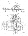
- the figures show a section of a packaging machine with an ejection device 10.
- a first conveyor 13 which may be a belt conveyor or other linear conveyor, several products P, P 'are arranged in a row at a mutual distance from the ejection device 10 in the transport direction T supplied.
- products P, P 'folding boxes are shown, but other products are conceivable.
- the ejection device 10 is arranged, to which a second secondary conveyor device 14 preferably of the same design follows. Between the first conveyor device 13 and the second conveyor device 14, a gap 15 is provided which is sufficiently large so that a product P, P 'can fall down through the gap 15.
- Each disk 12 has close to the axis of rotation 19, a base portion 12a, to which a fan-like radially outwardly widening portion 12b connects on diametrically opposite sides.
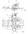
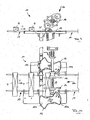
- FIG. 2 shows the discs 12 in their functional position in which they engage with their respective gap 15 facing fan-like portion 12b far into the gap 15 that the gap 15 is covered so far that a product P, P 'not through the gap down through can fall.
- the discs 12 are each rotated by about 90 ° (see Figures 10 and 12 )
- the two fan-like portions 12b of each disc 12 are disposed laterally adjacent to the gap 15 and do not engage therein.
- the gap 15 is large enough that a product P.P 'can fall down through the gap 15.
- the discs 12 are synchronized in their rotational movements and preferably each equipped with its own drive devices in the form of a servomotor. Each disc 12 is unidirectionally rotationally driven, ie it is rotated in one direction only and is not reciprocated. The discs 12 rotate in opposite directions relative to each other, with the rotation of each disc 12 being oriented so that the end of the disc 12 engaging in the gap 15 moves in the transporting direction T of the products, as indicated by the arrows A in the figures.
- a pusher 20 which has the task, a bad product P ', which is to be excreted through the gap 15 down to press reliably into the gap 15.
- the pusher 20 comprises a shaft 21 which is rotated by a drive device 18 in rotation and the axis of rotation 17 perpendicular to the plane in FIG. 1 , ie perpendicular to the transport direction T of the products P and perpendicular to the axis of rotation 19 of the discs 12 extends.
- two thrust plates 16 are arranged above the gap 15, which have an elliptical shape, extending in the transport direction T and whose plate plane is aligned perpendicular to the transport surface of the conveyors 13 and 14.
- the Figures 1 and 2 show the initial state in which the bad product P 'to be ejected is at the end of the first conveyor 13.
- the discs 12 are still in each case their functional position, ie they engage with their facing fan-shaped sections 12b in the gap 15 inside.
- the thrust plates 16 are aligned so that the longer major axis of the ellipse in the transport direction T has.
- the ejector 10 receives from the control of the packaging machine the signal to eliminate the bad product P '.
- the discs 12 are rotated in opposite directions, whereby the fan-like portions 12b of the discs 12, which until then have engaged in the gap 15, are swiveled out of the gap 15 in the direction of the further conveying device 14 (see FIG FIGS.
- the thrust plates 16 are rotated.
- the rotation of the thrust plates 16 is coordinated with the transport movement of the bad product P 'such that the thrust plates 16 come into abutment with the top of the bad product P' once it has left the first conveyor 13 and is above the gap 15.
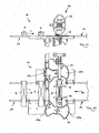
- the thrust plates 16 push the bad product P 'down into the gap 15 (FIG. Figures 9 and 11 ), so that the bad product P 'is ejected down through the gap 15 or excreted (see Figures 13 and 15 ).
- the bad product P ' is either collected in a container or discharged from the packaging machine.
- the thrust plates 16 continue to rotate until they return to their original position ( FIG. 15 ) have reached, in which a product P, which should not be excreted, can be transported below the thrust plates 16.
- the gap 15 was opened so far that the bad product P 'through the gap 15th could fall through.
- the gap is reduced again by now the other fan-like portions 12b of the discs 12 engage in the gap 15 (see Figures 14 and 16 ) and thereby form a bridge on which the product P, which should not be excreted, can be transferred to the further conveying device 14 (see FIGS. 15 and 16 ).
Landscapes
- Engineering & Computer Science (AREA)
- Mechanical Engineering (AREA)
Description
- Die Erfindung betrifft eine Verpackungsmaschine, in der Produkte in einer Reihe längs einer vorbestimmten Transportfläche bewegbar sind, mit einer Auswurfvorrichtung, in der ein vorbestimmtes Produkt aus der Reihe entfernbar ist, wobei die Auswurfvorrichtung zumindest ein Bodenteil aufweist, das zwischen einer Funktionsstellung, in der das Bodenteil einen Abschnitt der Transportfläche bildet, und einer Freigabestellung verstellbar ist, in der das Bodenteil aus der Transportfläche herausbewegt ist. Derartige Verpackungsmaschinen sind z.B. aus der
EP 1015362 bekannt. - In einer Verpackungsmaschine wird eine Ware mit einer Verpackung und/oder einer Umverpackung versehen. Im Folgenden soll beispielhaft von einer Kartoniermaschine ausgegangen werden, in der eine Ware in eine Faltschachtel eingeschoben und mit dieser zu weiteren Arbeitsstationen transportiert wird. Die Erfindung ist jedoch nicht auf eine Kartoniermaschine beschränkt und kann bei allen Verpackungsmaschinen Anwendung finden, bei denen die Produkte in einer Reihe längs einer vorbestimmten Transportbahn oder -fläche bewegt werden.
- In einer Verpackungsmaschine werden die Produkte daraufhin überprüft, ob sie gewisse Anforderungen erfüllen. Wenn ein Produkt eine dieser Anforderungen nicht erfüllt, wird es als sogenanntes "Schlecht-Produkt" eingestuft und muss aus der Produktreihe entfernt werden. Dies kann entweder dadurch geschehen, dass das Produkt manuell oder beispielsweise mit einem Roboter von oben aus der Reihe herausgehoben wird, alternativ ist es jedoch auch bekannt, das Schlecht-Produkt nach unten aus der im wesentlichen horizontal transportierten Reihe von Produkten auszuscheiden. Zu diesem Zweck ist zwischen einer 1. Fördervorrichtung und einer 2. Fördervorrichtung eine Lücke vorgesehen, in der eine Bodenklappe angeordnet ist. Wenn die Bodenklappe geschlossen ist, wird das Produkt über die Oberfläche der Bodenklappe von der 1. Fordervorrichtung an die weiterführende 2. Fördervorrichtung übergeben. Wenn ein Produkt ausgeschieden werden soll, wird die Bodenklappe geoffnet, so dass das in diesem Moment oberhalb der Bodenklappe befindliche Produkt durch die von der Bodenklappe gebildete Öffnung nach unten fällt. Anschließend wird die Klappe unverzüglich wieder geschlossen, um das nächste Produkt sicher an die weiterführende 2. Fordervorrichtung zu übergeben.
- Es ist auch bekannt, statt einer schwenkbaren Bodenklappe eine verschiebliche Bodenplatte zu verwenden, die im Bedarfsfall seitlich aus der Transportfläche herausgezogen wird, so dass das Produkt nach unten fällt, woraufhin die Bodenplatte wieder in die Transportfläche eingeschoben und somit die Lücke geschlossen wird.
- Alle genannten Vorgehensweisen zum Ausscheiden oder Auswerfen eines Schlecht-Produktes weisen den Nachteil auf, dass die jeweilige Zykluszeit, d.h. die Zeit, die gebraucht wird, um ein Schlecht-Produkt auszuscheiden und anschließend die Transportfläche wieder herzustellen, sehr lang ist, wodurch die Leistung der Verpackungsmaschine beschränkt ist. Darüber hinaus werden sowohl bei der schwenkbaren Bodenklappe als auch bei der verschieblichen Bodenplatte relativ große Massen bewegt, was zu ungleichmäßigen Bewegungen und hohen Belastungen der Bauteile führt.
- Der Erfindung liegt die Aufgabe zugrunde, eine Verpackungsmaschine mit einer Auswurfvorrichtung der genannten Art zu Schaffen, mit der sich in zuverlässiger Weise sehr kurze Zykluszeiten erzielen lassen.
- Diese Aufgabe wird erfindungsgemäß durch eine Verpackungsmaschine mit einer Auswurfvorrichtung mit den Merkmalen des Anspruchs 1 gelöst. Dabei ist vorgesehen, dass das Bodenteil eine drehangetriebene Scheibe mit einen rotationsasymmetrischen Querschnitt ist, die um eine Drehachse drehbar gelagert ist, und dass oberhalb der Lücke eine Schubvorrichtung angeordnet ist, mittels der auf ein darunter liegendes Produkt eine in die Lücke gerichtete Kraft aufbringbar ist.
- Dabei ist erfindungsgemäß vorzugsweise vorgesehen, dass die Transportbahn oder -fläche eine 1. Fördervorrichtung und eine daran anschließende 2. Fördervorrichtung umfasst, wobei zwischen den Fördervorrichtungen eine Lücke gebildet ist, in der die zumindest eine Scheibe zumindest abschnittsweise angeordnet ist.
- In ihrer Funktionsstellung ragt die Scheibe derart in die Lücke zwischen den Fördervorrichtungen hinein, dass das Produkt von der 1. Fördervorrichtung über die Scheibe zu der 2. Fördervorrichtung übergeben werden kann. Dabei kann das Produkt entweder über die ruhende Scheibe gleiten, alternativ ist es jedoch auch möglich, dass die Scheibe sich auch bei der Übergabe eines Produktes dreht und dadurch die Übergabe unterstützt, womit der weitere Vorteil gegeben ist, dass zwischen dem Produkt und der Scheibe eine geringere Relativbewegung stattfindet, so dass die Gefahr der Beschädigung des Produktes herabgesetzt ist.
- Wenn ein Schlecht-Produkt ausgeschieden oder ausgeworfen werden soll, dreht sich die Scheibe in eine Freigabestellung, in der sie aus der Transportfläche bzw. der Lücke zwischen den beiden Fördervorrichtungen soweit heraus bewegt ist, dass das Produkt durch die Lücke nach unten herunterfallen kann.
- Mit der Drehung einer Scheibe lassen sich sehr schnelle Bewegungen erzielen, so dass die Zykluszeit gegenüber den vorbekannten Bodenteilen wesentlich herabgesetzt ist.
- Um ein Schlecht-Produkt aus der Reihe der Produkte zu entfernen, wird die Scheibe in ihre Freigabestellung gedreht, in der zwischen der 1. Fördervorrichtung und der weiterführenden 2. Fördervorrichtung eine zumindest so große Lücke gebildet ist, dass das Schlecht-Produkt durch die Lücke nach unten fallen kann. Dabei ist vorgesehen, dass oberhalb der Lücke eine Schubvorrichtung angeordnet ist, mittels der auf ein darunter angeordnetes Produkt und insbesondere ein auszuscheidendes Schlecht-Produkt eine in die Lücke gerichtete Kraft aufbringbar ist. Die Schubvorrichtung stellt einerseits sicher, dass das Schlecht-Produkt durch die Lücke nach unten ausgeschieden wird, und verhindert andererseits, dass das Schlechtprodukt irrtümlicherweise auf die weiterführende 2. Fördervorrichtung gelangt und somit in der Produktreihe verbleibt.
- In bevorzugter Ausgestaltung der Erfindung ist vorgesehen, dass zwei Scheiben auf Abstand nebeneinander angeordnet sind, die von entegegengesetzten Seiten in die Transportfläche bzw. in die zwischen den Fördervorrichtungen gebildete Lücke eingreifen. Aufgrund der Verwendung von zwei Scheiben können diese jeweils relativ klein und kompakt ausgebildet sein, wodurch sie einerseits einen nur geringen Bauraum erfordern und andererseits sehr schnell gedreht werden können.
- Die Scheiben sollten in ihren Drehbewegungen synchronisiert sein. Dazu kann einerseits vorgesehen sein, dass für die Scheiben eine gemeinsame Antriebsvorrichtung vorgesehen ist, alternativ ist es jedoch auch möglich, jeder Scheibe eine eigene Antriebsvorrichtung, insbesondere einen Servomotor, zuzuordnen und die Antriebsvorrichtungen mittels ei-, ner elektronischen Steuerung zu synchronisieren.
- Jede Scheibe ist vorzugsweise einsinnig bzw. unidirektional drehangetrieben, d.h. sie wird nur in eine Richtung gedreht und nicht hin und her bewegt. Wenn zwei Scheiben auf entgegengesetzten Seiten der Lücke angeordnet sind, drehen die beiden Scheiben relativ zueinander gegensinnig. Dabei ist die Drehung jeder Scheibe vorzugsweise so ausgerichtet, dass das in die Lücke eingreifende Ende der Scheibe sich in Transportrichtung bewegt.
- In ihrer Funktionsstellung bildet die Oberfläche der Scheibe bzw. der Scheiben einen Teil der Transportfläche, wobei die Oberfläche vorzugsweise in einer Ebene mit der Transportfläche der 1. Fördervorrichtung und/oder der Transportfläche der 2. Fördervorrichtung liegt. Die Drehachse der Scheibe verläuft vorzugsweise normal zu derjenigen Oberfläche der Scheibe, die ein Abschnitt der Transportbahn bildet, d.h. normal zu der Transportfläche, über die die Produkte bewegt werden.
- Als besonders vorteilhaft hat es sich erwiesen, wenn die Scheibe nahe der Drehachse einen Basisabschnitt aufweist, an den sich zumindest ein sich fächerartig radial nach außen erweiternder Abschnitt anschließt. Es können auch mehrere entsprechende fächerartige Abschnitte über den Umfang des Basisabschnitts verteilt angeordnet sein. Vorteilhafterweise ist vorgesehen, dass die Scheibe zwei fächerartige Abschnitte auf entgegengesetzten Seiten des Basisabschnitts besitzt.
- In bevorzugter Ausgestaltung der Erfindung ist vorgesehen, dass die Schubvorrichtung zumindest eine drehbar gelagerte Schubplatte und insbesondere zumindest zwei auf Abstand parallel nebeneinander angeordnete Schubplatten umfasst. Die Schubplatten sind im wesentlichen vertikal ausgerichtet, d.h. ihre Plattenebene verläuft senkrecht zu der Transportfläche, auf der die Produkte transportiert werden. Die Schubplatte oder Schubplatten sind vorzugsweise um eine Achse drehbar, die senkrecht zur Transportrichtung der Produkte und senkrecht zu der Drehachse der Scheibe verläuft. Die Drehung ist dabei vorzugsweise so ausgerichtet, dass das zum Produkt weisende untere Ende der Schubplatte oder Schubplatten in Transportrichtung der Produkte bewegt wird. Bei Anordnung mehrere Schubplatten sollten diese auf einer gemeinsamen Welle sitzen und von einer gemeinsamen Antriebsvorrichtung, beispielsweise einem Servomotor angetrieben sein.
- Um zu vermeiden, dass sich die Schubplatte mit einem Produkt verhakt oder auf dieses eine hohe punktuelle Last aufbringt, ist erfindungsgemäß in Weiterbildung der Erfindung vorgesehen, dass die Schubplatte abgerundet ist und insbesondere eine elliptische Form besitzt.
- Wenn die Scheibe bzw. Scheiben in ihrer Funktionsstellung, in der sie die Lücke zwischen den Fördervorrichtungen überbrücken, still stehen, muss auf das von der 1. Fördervorrichtung auf die Scheibe bzw. Scheiben gelangende Produkte ein Schubkraft aufgebracht werden, um es zu der weiterführenden 2. Fördervorrichtung zu schieben. Die Aufbringung dieser Schubkraft kann durch die Schubplatte bzw. Schubplatten erreicht werden.
- Alternativ ist es möglich, die Scheibe oder Scheiben in ihrer Funktionsstellung ebenfalls zu drehen, so dass auf das auf der Scheibe oder den Scheiben aufliegende Produkt aufgrund der Reibung mit der Oberfläche der Scheibe oder Scheiben eine zu der weiterführenden 2. Fördervorrichtung gerichtete Kraft aufgebracht werden kann.
- Weitere Einzelheiten und Merkmale der Erfindung sind aus der folgenden Beschreibung eines Ausführungsbeispiels unter Bezugnahme auf die Zeichnung ersichtlich. Es zeigen:
- Fig. 1
- eine Auswurfvorrichtung in einer Verpackungsmaschine zu Beginn eines Zyklus eines Produktauswurfs,
- Fig. 2
- eine Aufsicht auf die Auswurfvorrichtung gemäß
Figur 1 , - Fig. 3
- die Auswurfvorrichtung gemäß
Figur 1 in einer 1. Phase des Auswurf-Zyklus, - Fig. 4
- eine Aufsicht auf die Auswurfvorrichtung gemäß
Figur 3 , - Fig. 5
- die Auswurfvorrichtung gemäß
Figur 1 in einer 2. Phase des Auswurf-Zyklus, - Fig. 6
- eine Aufsicht auf die Auswurfvorrichtung gemäß
Figur 5 , - Fig. 7
- die Auswurfvorrichtung gemäß
Figur 1 in einer 3. Phase des Auswurf-Zyklus, - Fig. 8
- eine Aufsicht auf die Auswurfvorrichtung gemäß
Figur 7 , - Fig. 9
- die Auswurfvorrichtung gemäß
Figur 1 in einer 4. Phase des Auswurf-Zyklus, - Fig. 10
- eine Aufsicht auf die Auswurfvorrichtung gemäß
Figur 9 , - Fig. 11
- die Auswurfvorrichtung gemäß
Figur 1 in einer 5. Phase des Auswurf-Zyklus, - Fig. 12
- eine Aufsicht auf die Auswurfvorrichtung gemäß
Figur 11 , - Fig. 13
- die Auswurfvorrichtung gemäß
Figur 1 in einer 6. Phase des Auswurf-Zyklus, - Fig. 14
- eine Aufsicht auf die Auswurfvorrichtung gemäß
Figur 13 , - Fig. 15
- die Auswurfvorrichtung gemäß
Figur 1 bei Übergabe eines Produktes an die weiterführende Fördervorrichtung und - Fig. 16
- eine Aufsicht auf die Auswurfvorrichtung gemäß
Figur 15 . - Die Figuren zeigen einen Ausschnitt aus einer Verpackungsmaschine mit einer Auswurfvorrichtung 10. Auf einer 1. Fördervorrichtung 13, bei der es sich um einen Bandförderer oder einen sonstigen linearen Förderer handeln kann, werden mehrere Produkte P, P' in einer Reihe in gegenseitigem Abstand der Auswurfvorrichtung 10 in Transportrichtung T zugeführt. Als Produkte P, P' sind Faltschachteln dargestellt, jedoch sind auch andere Produkte denkbar. Am Ende der 1. Fördervorrichtung 13 ist die Auswurfvorrichtung 10 angeordnet, an die sich eine 2. weiterführende Fördervorrichtung 14 vorzugsweise gleicher Bauart anschließt. Zwischen der 1. Fördervorrichtung 13 und der 2. Fördervorrichtung 14 ist eine Lücke 15 vorgesehen, die ausreichend groß ist, so dass ein Produkt P, P' durch die Lücke 15 nach unten herausfallen kann.
- Im Bereich der Lücke 15 ist auf jeder Seite der Fördervorrichtungen 13 und 14 jeweils ein Bodenteil 11 in Form einer drehangetriebenen Scheibe 12 vorgesehen, deren Oberflächen mit den Transportebenen oder -flächen der Fördervorrichtungen 13 und 14 in einer Ebene liegen. Die Scheiben 12 sind jeweils um eine Drehachse 19 drehbar, die normal zur Transportfläche der Fördervorrichtungen 13 und 14 sowie normal zu derjenigen Oberfläche der Scheibe 12 verläuft, die einen Abschnitt der Transportfläche bildet.
- Jede Scheibe 12 besitzt nahe der Drehachse 19 einen Basisabschnitt 12a, an den sich auf diametral entgegengesetzten Seiten jeweils ein fächerartig radial nach außen erweiternder Abschnitt 12b anschließt.
-
Figur 2 zeigt die Scheiben 12 in ihrer Funktionsstellung, in der sie jeweils mit ihrem der Lücke 15 zugewandten fächerartigen Abschnitt 12b soweit in die Lücke 15 eingreifen, dass die Lücke 15 soweit abgedeckt ist, dass ein Produkt P, P' nicht durch die Lücke nach unten hindurch fallen kann. Wenn die Scheiben 12 jeweils um ca. 90° gedreht sind (sieheFiguren 10 und12 ), sind die beiden fächerartigen Abschnitte 12b jeder Scheibe 12 seitlich neben der Lücke 15 angeordnet und greifen nicht in diese hinein. Somit ist die Lücke 15 groß genug, dass ein Produkt P. P' nach unten durch die Lücke 15 hindurch fallen kann. - Die Scheiben 12 sind in ihren Drehbewegungen synchronisiert und vorzugsweise jeweils mit eigenen Antriebsvorrichtungen in Form eines Servomotors ausgerüstet. Jede Scheibe 12 ist einsinnig bzw. unidirektional drehangetrieben, d.h. sie wird in nur eine Richtung gedreht und nicht hin und her bewegt. Die Scheiben 12 drehen relativ zueinander gegensinnig, wobei die Drehung jeder Scheibe 12 so ausgerichtet ist, dass das in die Lücke 15 eingreifende Ende der Scheibe 12 sich in Transportrichtung T der Produkte bewegt, wie es durch die Pfeile A in den Figuren angedeutet ist.
- Oberhalb der Lücke 15 im Abstand zu dieser ist eine Schubvorrichtung 20 angeordnet, die die Aufgabe hat, ein Schlecht-Produkt P', das durch die Lücke 15 nach unten ausgeschieden werden soll, zuverlässig in die Lücke 15 hineinzudrücken. Die Schubvorrichtung 20 umfasst eine Welle 21, die von einer Antriebsvorrichtung 18 in Drehung versetzt wird und deren Drehachse 17 senkrecht zur Zeichenebene in
Figur 1 , d.h. senkrecht zur Transportrichtung T der Produkte P und senkrecht zu der Drehachse 19 der Scheiben 12 verläuft. Auf der Welle 21 sind oberhalb der Lücke 15 zwei Schubplatten 16 angeordnet, die eine elliptische Form besitzen, sich in Transportrichtung T erstrecken und deren Plattenebene senkrecht zur Transportfläche der Fördervorrichtungen 13 und 14 ausgerichtet ist. Wenn sich die elliptischen Schubplatten 16 in der inFigur 1 dargestellten Stellung befinden, in der die längere Hauptachse der Ellipse parallel zur Transportrichtung T verläuft, ist der Abstand zwischen der Unterkante der Schubplatten 16 und der Oberseite der Scheiben 12 so groß, dass das Produkt P, P' unterhalb der Schubplatten 16 hindurchbewegt werden kann. Die Drehung der Schubplatten 16 ist so ausgerichtet, dass das zum Produkt P, P' weisende untere Ende der Schubplatten 16 in Transportrichtung T bewegt wird, wie es in der Abfolge derFiguren 7 ,9 ,11 und13 ersichtlich ist. - Im Folgenden soll anhand der Figuren der Vorgang des Ausscheidens eines Schlecht-Produktes P' im Einzelnen erläuterte werden.
- Die
Figuren 1 und 2 zeigen den Ausgangszustand, in dem das auszuwerfende Schlecht-Produkt P' am Ende der 1. Fördervorrichtung 13 steht. Die Scheiben 12 stehen jeweils noch in ihrer Funktionsstellung, d.h. sie greifen mit ihren einander zugewandten fächerförmigen Abschnitten 12b in die Lücke 15 hinein. Die Schubplatten 16 sind so ausgerichtet, dass die längere Hauptachse der Ellipse in Transportrichtung T weist. Ausgehend von diesem Zustand bekommt die Auswurfvorrichtung 10 von der Steuerung der Verpackungsmaschine das Signal, das Schlecht-Produkt P' auszuscheiden. Zu diesem Zweck werden die Scheiben 12 gegenläufig in Drehung versetzt, wobei die bislang in die Lücke 15 eingreifenden fächerartigen Abschnitte 12b der Scheiben 12 in Richtung der weiterführenden Fördervorrichtung 14 aus der Lücke 15 herausgeschwenkt werden (sieheFiguren 4 ,6 ,8 und10 ). Gleichzeitig werden die Schubplatten 16 in Drehung versetzt. Die Drehung der Schubplatten 16 ist mit der Transportbewegung des Schlecht-Produktes P' so koordiniert, dass die Schubplatten 16 mit der Oberseite des SchlechtProduktes P' in Anlage kommen, sobald dieses die 1. Fördervorrichtung 13 verlassen hat und sich oberhalb der Lücke 15 befindet. In diesem Zustand (sieheFigur 9 ) drücken die Schubplatten 16 das Schlecht-Produkt P' nach unten in die Lücke 15 (Figuren 9 und11 ), so dass das Schlecht-Produkt P' durch die Lücke 15 nach unten ausgeworfen oder ausgeschieden wird (sieheFiguren 13 und15 ). Üblicherweise wird das Schlecht-Produkt P' entweder in einem Behälter gesammelt oder aus der Verpackungsmaschine abgeführt. - Die Schubplatten 16 drehen weiter, bis sie wieder ihre Ausgangsstellung (
Figur 15 ) erreicht haben, in der ein Produkt P, das nicht ausgeschieden werden soll, unterhalb der Schubplatten 16 hindurchtransportiert werden kann. - Durch Drehung der Scheiben 12 wurde die Lücke 15 soweit geöffnet, dass das Schlecht-Produkt P' durch die Lücke 15 hindurch fallen konnte. Bei weiterer Drehung der Scheiben 12 wird die Lücke wieder verkleinert, indem nunmehr die jeweils anderen fächerartigen Abschnitte 12b der Scheiben 12 in die Lücke 15 eingreifen (siehe
Figuren 14 und16 ) und dadurch eine Brücke bilden, auf der das Produkt P, das nicht ausgeschieden werden soll, an die weiterführende Fördervorrichtung 14 übergeben werden kann (sieheFiguren 15 und 16 ).
Claims (11)
- Verpackungsmaschine, in der Produkte (P, P') in einer Reihe längs einer vorbestimmten Transportfläche bewegbar sind, mit einer Auswurfvorrichtung (10), in der ein vorbestimmtes Produkt (P') aus der Reihe entfernbar ist, wobei die Auswurfvorrichtung (10) zumindest ein Bodenteil (11) aufweist, das zwischen einer Funktionsstellung, in der das Bodenteil (11) einen Abschnitt der Transportfläche bildet, und einer Freigabestellung verstellbar ist, in der das Bodenteil (11) aus der Transportfläche herausbewegt ist, wobei das Bodenteil (11) eine drehangetriebene Scheibe (12) mit einem rotationsasymmetrischen Querschnitt ist, die um eine Drehachse (19) drehbar gelagert ist und wobei die Transportfläche eine 1. Fördervorrichtung (13) und eine daran anschließende 2. Fördervorrichtung (14) umfasst, wobei zwischen den Fördervorrichtungen (13, 14) eine Lücke (15) gebildet ist, in der die zumindest eine Scheibe (12) zumindest abschnittsweise angeordnet ist, dadurch gekennzeichnet, dass oberhalb der Lücke (15) eine Schubvorrichtung (20) angeordnet ist, mittels der auf ein darunter liegendes Produkt (P, P') eine in die Lücke (15) gerichtete Kraft aufbringbar ist.
- Verpackungsmaschine nach Anspruch 1, dadurch gekennzeichnet, dass zwei Scheiben (12) auf Abstand nebeneinander angeordnet sind, die von entgegengesetzten Seiten in die Lücke (15) eingreifen.
- Verpackungsmaschine nach Anspruch 2, dadurch gekennzeichnet, dass die Scheiben (12) in ihren Drehbewegungen synchronisiert sind.
- Verpackungsmaschine nach einem der Ansprüche 1 bis 3, dadurch gekennzeichnet, dass die Scheibe (12) einsinnig drehangetrieben ist.
- Verpackungsmaschine nach einem der Ansprüche 1 bis 4, dadurch gekennzeichnet, dass die Drehachse (19) normal zu derjenigen Oberfläche der Scheibe verläuft, die einen Abschnitt der Transportfläche bildet.
- Verpackungsmaschine nach einem der Ansprüche 1 bis 5, dadurch gekennzeichnet, dass die Scheibe (12) nahe der Drehachse (19) einen Basisabschnitt (12a) aufweist, an den sich zumindest ein sich fächerartig radial nach außen erweiternder Abschnitt (12b) anschließt.
- Verpackungsmaschine nach Anspruch 6, dadurch gekennzeichnet, dass die Scheibe (12) zwei fächerartige Abschnitte (12b) auf entgegengesetzten Seiten des Basisabschnitts (12a) aufweist.
- Verpackungsmaschine nach einem der Ansprüche 1 bis 7, dadurch gekennzeichnet, dass die Schubvorrichtung (20) zumindest eine drehbar gelagerte Schubplatte (16) umfasst.
- Verpackungsmaschine nach Anspruch 8, dadurch gekennzeichnet, dass die zumindest zwei Schubplatten (16) auf Abstand parallel nebeneinander angeordnet sind.
- Verpackungsmaschine nach Anspruch 8 oder 9, dadurch gekennzeichnet, dass die Schubplatte (16) eine elliptische Form besitzt.
- Verpackungsmaschine nach einem der Ansprüche 8 bis 10, dadurch gekennzeichnet, dass die Schubplatte (16) um eine Achse (17) drehbar ist, die senkrecht zur Transportrichtung (T) der Produkte (P) und senkrecht zu der Drehachse (19) der Scheibe (12) verläuft.
Priority Applications (1)
| Application Number | Priority Date | Filing Date | Title |
|---|---|---|---|
| PL12705056T PL2643224T3 (pl) | 2011-02-18 | 2012-02-14 | Maszyna pakująca z urządzeniem wyrzutowym |
Applications Claiming Priority (2)
| Application Number | Priority Date | Filing Date | Title |
|---|---|---|---|
| DE102011011642A DE102011011642A1 (de) | 2011-02-18 | 2011-02-18 | Verpackungsmaschine |
| PCT/EP2012/000635 WO2012110225A1 (de) | 2011-02-18 | 2012-02-14 | Verpackungsmaschine mit auswurfvorrichtung |
Publications (2)
| Publication Number | Publication Date |
|---|---|
| EP2643224A1 EP2643224A1 (de) | 2013-10-02 |
| EP2643224B1 true EP2643224B1 (de) | 2014-09-17 |
Family
ID=45722576
Family Applications (1)
| Application Number | Title | Priority Date | Filing Date |
|---|---|---|---|
| EP12705056.5A Active EP2643224B1 (de) | 2011-02-18 | 2012-02-14 | Verpackungsmaschine mit auswurfvorrichtung |
Country Status (6)
| Country | Link |
|---|---|
| EP (1) | EP2643224B1 (de) |
| BR (1) | BR112013017436B1 (de) |
| DE (1) | DE102011011642A1 (de) |
| MX (1) | MX336373B (de) |
| PL (1) | PL2643224T3 (de) |
| WO (1) | WO2012110225A1 (de) |
Families Citing this family (1)
| Publication number | Priority date | Publication date | Assignee | Title |
|---|---|---|---|---|
| JP6388049B2 (ja) * | 2016-04-05 | 2018-09-12 | キヤノンマーケティングジャパン株式会社 | 薬剤包装装置 |
Family Cites Families (11)
| Publication number | Priority date | Publication date | Assignee | Title |
|---|---|---|---|---|
| US2601514A (en) * | 1948-01-21 | 1952-06-24 | William T Goodban | Can sorting machine |
| GB1307031A (en) * | 1971-04-08 | 1973-02-14 | Mitsubushi Chemical Ind Ltd | Apparatus for charging sample |
| US4011155A (en) * | 1975-03-31 | 1977-03-08 | Pemco, Inc. | Wrapped package inspection and rejection apparatus |
| DE2710040C2 (de) * | 1977-03-08 | 1981-10-08 | Mayer KG Apparate und Maschinenbau, 7920 Heidenheim | Übergabe- und Transportvorrichtung für Gegenstände |
| DE3149583C2 (de) * | 1981-12-15 | 1984-07-05 | Bernhard Beumer Maschinenfabrik Kg, 4720 Beckum | Vorrichtung zum Identifizieren defekter Schüttguteinheiten |
| US5042637A (en) * | 1990-03-08 | 1991-08-27 | Sunkist Growers, Inc. | Conveyor discharge apparatus and method |
| DE4129612C2 (de) * | 1991-09-06 | 1995-10-05 | Ems Elektronik Mestechnik Dipl | Auswerfvorrichtung zum gesteuerten Aussondern flacher Gegenstände, die gefächert über ein Transportband geführt werden |
| US6076653A (en) * | 1997-04-29 | 2000-06-20 | United Parcel Service Of America, Inc. | High speed drum sorting conveyor system |
| JP2003011931A (ja) * | 2001-06-25 | 2003-01-15 | Toyo Jidoki Co Ltd | リテーナからの製品袋の取出装置及び取出方法 |
| JP3102367U (ja) * | 2003-12-18 | 2004-07-02 | 株式会社プラスワンテクノ | スティック包装機 |
| PL1894863T3 (pl) * | 2006-09-01 | 2011-07-29 | Food Processing Systems | Urządzenie dozujące |
-
2011
- 2011-02-18 DE DE102011011642A patent/DE102011011642A1/de not_active Withdrawn
-
2012
- 2012-02-14 PL PL12705056T patent/PL2643224T3/pl unknown
- 2012-02-14 MX MX2013007450A patent/MX336373B/es unknown
- 2012-02-14 EP EP12705056.5A patent/EP2643224B1/de active Active
- 2012-02-14 WO PCT/EP2012/000635 patent/WO2012110225A1/de not_active Ceased
- 2012-02-14 BR BR112013017436A patent/BR112013017436B1/pt not_active IP Right Cessation
Also Published As
| Publication number | Publication date |
|---|---|
| MX2013007450A (es) | 2013-07-22 |
| WO2012110225A1 (de) | 2012-08-23 |
| BR112013017436A2 (pt) | 2016-09-27 |
| BR112013017436B1 (pt) | 2019-12-24 |
| EP2643224A1 (de) | 2013-10-02 |
| PL2643224T3 (pl) | 2015-03-31 |
| MX336373B (es) | 2016-01-18 |
| DE102011011642A1 (de) | 2012-08-23 |
Similar Documents
| Publication | Publication Date | Title |
|---|---|---|
| DE69500340T2 (de) | Vorrichtung zum Öffnen und Zuführen von Schachteln | |
| EP2816305B1 (de) | Vorrichtung zum Be- und Entladen einer Stellplatte einer Gefriertrocknungsanlage und ein Verfahren hierfür | |
| EP2881332B1 (de) | Transportvorrichtung zum Fördern von Produkten | |
| EP2439142B1 (de) | Vorrichtung zum Transportieren und Einschieben von Packgut | |
| EP2228181A1 (de) | Produktgreifer | |
| EP2103556A1 (de) | Palettiervorrichtung | |
| DE102007034197A1 (de) | Vorrichtung zum Be- und Entladen einer Stellplatte einer Gefriertrocknungsanlage und ein Verfahren hierfür | |
| DE102021209986A1 (de) | Handhabungssystem zur automatischen Übergabe und Vereinzelung von Ladungsträgern | |
| DE2816235A1 (de) | Geraet zum zusammenklappen von schachtelzuschnitten | |
| EP2939965B1 (de) | Schiebevorrichtung für eine palettiervorrichtung mit einem schieber, widerlager und mit zwei ausrichtdrücker | |
| EP0338281A1 (de) | Verfahren und Vorrichtung zum Öffnen der Verschlussklappen eines Kartons | |
| EP2709912B1 (de) | Verfahren und vorrichtung zum herstellen von packungen des typs klappschachtel für zigaretten | |
| EP2643224B1 (de) | Verpackungsmaschine mit auswurfvorrichtung | |
| EP3499160A1 (de) | Gefriertrockner, gefriertrocknungsanlage, verfahren zum betrieb eines gefriertrockners und neue verwendung eines schlittens | |
| DE1925777A1 (de) | Vorrichtung zur UEberfuehrung von Gegenstaenden,insbesondere von nicht anhaeufbaren Gegenstaenden,von einer Abgabeeinrichtung zu einer sich mit anderer Geschwindigkeit bewegenden Aufnahmeeinrichtung | |
| EP2062838B1 (de) | Verfahren und Vorrichtung zur Entfernung von Zwischenablagen von palettierten Waren und Gütern | |
| DE102010028766A1 (de) | Aufklappvorrichtung | |
| WO2018234111A1 (de) | Eierausrichtungsstation zur ausrichtung von eiern und vorrichtung zum transport und verpacken von eiern | |
| DE4436075C2 (de) | Vorrichtung zum Palettieren von Stückgütern zu einem Stückgutstapel | |
| EP1593633B1 (de) | Vorrichtung zum Bilden von Stapeln aus Druckprodukten | |
| DE2831685A1 (de) | Zufuehrmechanismus fuer verpackungsmaterial | |
| EP1832385B1 (de) | Vorrichtung zur Zuführung von Werkstücken zu einem Drehtisch | |
| DE102004054713A1 (de) | Vorrichtung zum Aufnehmen und Abgeben von Stückgut | |
| EP4107098A1 (de) | Fördervorrichtung für vereinzelte erzeugnisse | |
| EP4186828B1 (de) | Vorrichtung und verfahren zum zusammenstellen von stückgutlagen |
Legal Events
| Date | Code | Title | Description |
|---|---|---|---|
| PUAI | Public reference made under article 153(3) epc to a published international application that has entered the european phase |
Free format text: ORIGINAL CODE: 0009012 |
|
| 17P | Request for examination filed |
Effective date: 20130611 |
|
| AK | Designated contracting states |
Kind code of ref document: A1 Designated state(s): AL AT BE BG CH CY CZ DE DK EE ES FI FR GB GR HR HU IE IS IT LI LT LU LV MC MK MT NL NO PL PT RO RS SE SI SK SM TR |
|
| GRAP | Despatch of communication of intention to grant a patent |
Free format text: ORIGINAL CODE: EPIDOSNIGR1 |
|
| DAX | Request for extension of the european patent (deleted) | ||
| INTG | Intention to grant announced |
Effective date: 20140507 |
|
| GRAS | Grant fee paid |
Free format text: ORIGINAL CODE: EPIDOSNIGR3 |
|
| GRAP | Despatch of communication of intention to grant a patent |
Free format text: ORIGINAL CODE: EPIDOSNIGR1 |
|
| GRAA | (expected) grant |
Free format text: ORIGINAL CODE: 0009210 |
|
| INTG | Intention to grant announced |
Effective date: 20140724 |
|
| AK | Designated contracting states |
Kind code of ref document: B1 Designated state(s): AL AT BE BG CH CY CZ DE DK EE ES FI FR GB GR HR HU IE IS IT LI LT LU LV MC MK MT NL NO PL PT RO RS SE SI SK SM TR |
|
| REG | Reference to a national code |
Ref country code: GB Ref legal event code: FG4D Free format text: NOT ENGLISH |
|
| REG | Reference to a national code |
Ref country code: CH Ref legal event code: EP |
|
| REG | Reference to a national code |
Ref country code: IE Ref legal event code: FG4D Free format text: LANGUAGE OF EP DOCUMENT: GERMAN |
|
| REG | Reference to a national code |
Ref country code: AT Ref legal event code: REF Ref document number: 687565 Country of ref document: AT Kind code of ref document: T Effective date: 20141015 |
|
| REG | Reference to a national code |
Ref country code: DE Ref legal event code: R096 Ref document number: 502012001277 Country of ref document: DE Effective date: 20141030 |
|
| REG | Reference to a national code |
Ref country code: SE Ref legal event code: TRGR |
|
| PG25 | Lapsed in a contracting state [announced via postgrant information from national office to epo] |
Ref country code: FI Free format text: LAPSE BECAUSE OF FAILURE TO SUBMIT A TRANSLATION OF THE DESCRIPTION OR TO PAY THE FEE WITHIN THE PRESCRIBED TIME-LIMIT Effective date: 20140917 Ref country code: LT Free format text: LAPSE BECAUSE OF FAILURE TO SUBMIT A TRANSLATION OF THE DESCRIPTION OR TO PAY THE FEE WITHIN THE PRESCRIBED TIME-LIMIT Effective date: 20140917 Ref country code: NO Free format text: LAPSE BECAUSE OF FAILURE TO SUBMIT A TRANSLATION OF THE DESCRIPTION OR TO PAY THE FEE WITHIN THE PRESCRIBED TIME-LIMIT Effective date: 20141217 Ref country code: GR Free format text: LAPSE BECAUSE OF FAILURE TO SUBMIT A TRANSLATION OF THE DESCRIPTION OR TO PAY THE FEE WITHIN THE PRESCRIBED TIME-LIMIT Effective date: 20141218 |
|
| REG | Reference to a national code |
Ref country code: NL Ref legal event code: VDEP Effective date: 20140917 |
|
| REG | Reference to a national code |
Ref country code: LT Ref legal event code: MG4D |
|
| PG25 | Lapsed in a contracting state [announced via postgrant information from national office to epo] |
Ref country code: LV Free format text: LAPSE BECAUSE OF FAILURE TO SUBMIT A TRANSLATION OF THE DESCRIPTION OR TO PAY THE FEE WITHIN THE PRESCRIBED TIME-LIMIT Effective date: 20140917 Ref country code: HR Free format text: LAPSE BECAUSE OF FAILURE TO SUBMIT A TRANSLATION OF THE DESCRIPTION OR TO PAY THE FEE WITHIN THE PRESCRIBED TIME-LIMIT Effective date: 20140917 Ref country code: RS Free format text: LAPSE BECAUSE OF FAILURE TO SUBMIT A TRANSLATION OF THE DESCRIPTION OR TO PAY THE FEE WITHIN THE PRESCRIBED TIME-LIMIT Effective date: 20140917 Ref country code: CY Free format text: LAPSE BECAUSE OF FAILURE TO SUBMIT A TRANSLATION OF THE DESCRIPTION OR TO PAY THE FEE WITHIN THE PRESCRIBED TIME-LIMIT Effective date: 20140917 |
|
| PG25 | Lapsed in a contracting state [announced via postgrant information from national office to epo] |
Ref country code: NL Free format text: LAPSE BECAUSE OF FAILURE TO SUBMIT A TRANSLATION OF THE DESCRIPTION OR TO PAY THE FEE WITHIN THE PRESCRIBED TIME-LIMIT Effective date: 20140917 |
|
| REG | Reference to a national code |
Ref country code: PL Ref legal event code: T3 |
|
| PG25 | Lapsed in a contracting state [announced via postgrant information from national office to epo] |
Ref country code: IS Free format text: LAPSE BECAUSE OF FAILURE TO SUBMIT A TRANSLATION OF THE DESCRIPTION OR TO PAY THE FEE WITHIN THE PRESCRIBED TIME-LIMIT Effective date: 20150117 Ref country code: CZ Free format text: LAPSE BECAUSE OF FAILURE TO SUBMIT A TRANSLATION OF THE DESCRIPTION OR TO PAY THE FEE WITHIN THE PRESCRIBED TIME-LIMIT Effective date: 20140917 Ref country code: PT Free format text: LAPSE BECAUSE OF FAILURE TO SUBMIT A TRANSLATION OF THE DESCRIPTION OR TO PAY THE FEE WITHIN THE PRESCRIBED TIME-LIMIT Effective date: 20150119 Ref country code: SK Free format text: LAPSE BECAUSE OF FAILURE TO SUBMIT A TRANSLATION OF THE DESCRIPTION OR TO PAY THE FEE WITHIN THE PRESCRIBED TIME-LIMIT Effective date: 20140917 Ref country code: RO Free format text: LAPSE BECAUSE OF FAILURE TO SUBMIT A TRANSLATION OF THE DESCRIPTION OR TO PAY THE FEE WITHIN THE PRESCRIBED TIME-LIMIT Effective date: 20140917 Ref country code: EE Free format text: LAPSE BECAUSE OF FAILURE TO SUBMIT A TRANSLATION OF THE DESCRIPTION OR TO PAY THE FEE WITHIN THE PRESCRIBED TIME-LIMIT Effective date: 20140917 Ref country code: ES Free format text: LAPSE BECAUSE OF FAILURE TO SUBMIT A TRANSLATION OF THE DESCRIPTION OR TO PAY THE FEE WITHIN THE PRESCRIBED TIME-LIMIT Effective date: 20140917 |
|
| REG | Reference to a national code |
Ref country code: DE Ref legal event code: R097 Ref document number: 502012001277 Country of ref document: DE |
|
| PG25 | Lapsed in a contracting state [announced via postgrant information from national office to epo] |
Ref country code: BE Free format text: LAPSE BECAUSE OF NON-PAYMENT OF DUE FEES Effective date: 20150228 |
|
| PLBE | No opposition filed within time limit |
Free format text: ORIGINAL CODE: 0009261 |
|
| STAA | Information on the status of an ep patent application or granted ep patent |
Free format text: STATUS: NO OPPOSITION FILED WITHIN TIME LIMIT |
|
| PG25 | Lapsed in a contracting state [announced via postgrant information from national office to epo] |
Ref country code: DK Free format text: LAPSE BECAUSE OF FAILURE TO SUBMIT A TRANSLATION OF THE DESCRIPTION OR TO PAY THE FEE WITHIN THE PRESCRIBED TIME-LIMIT Effective date: 20140917 |
|
| 26N | No opposition filed |
Effective date: 20150618 |
|
| PG25 | Lapsed in a contracting state [announced via postgrant information from national office to epo] |
Ref country code: LU Free format text: LAPSE BECAUSE OF FAILURE TO SUBMIT A TRANSLATION OF THE DESCRIPTION OR TO PAY THE FEE WITHIN THE PRESCRIBED TIME-LIMIT Effective date: 20150214 |
|
| REG | Reference to a national code |
Ref country code: CH Ref legal event code: PL |
|
| PG25 | Lapsed in a contracting state [announced via postgrant information from national office to epo] |
Ref country code: LI Free format text: LAPSE BECAUSE OF NON-PAYMENT OF DUE FEES Effective date: 20150228 Ref country code: MC Free format text: LAPSE BECAUSE OF FAILURE TO SUBMIT A TRANSLATION OF THE DESCRIPTION OR TO PAY THE FEE WITHIN THE PRESCRIBED TIME-LIMIT Effective date: 20140917 Ref country code: CH Free format text: LAPSE BECAUSE OF NON-PAYMENT OF DUE FEES Effective date: 20150228 |
|
| REG | Reference to a national code |
Ref country code: IE Ref legal event code: MM4A |
|
| PG25 | Lapsed in a contracting state [announced via postgrant information from national office to epo] |
Ref country code: SI Free format text: LAPSE BECAUSE OF FAILURE TO SUBMIT A TRANSLATION OF THE DESCRIPTION OR TO PAY THE FEE WITHIN THE PRESCRIBED TIME-LIMIT Effective date: 20140917 |
|
| PG25 | Lapsed in a contracting state [announced via postgrant information from national office to epo] |
Ref country code: IE Free format text: LAPSE BECAUSE OF NON-PAYMENT OF DUE FEES Effective date: 20150214 |
|
| REG | Reference to a national code |
Ref country code: FR Ref legal event code: PLFP Year of fee payment: 5 |
|
| GBPC | Gb: european patent ceased through non-payment of renewal fee |
Effective date: 20160214 |
|
| PG25 | Lapsed in a contracting state [announced via postgrant information from national office to epo] |
Ref country code: MT Free format text: LAPSE BECAUSE OF FAILURE TO SUBMIT A TRANSLATION OF THE DESCRIPTION OR TO PAY THE FEE WITHIN THE PRESCRIBED TIME-LIMIT Effective date: 20140917 |
|
| PG25 | Lapsed in a contracting state [announced via postgrant information from national office to epo] |
Ref country code: GB Free format text: LAPSE BECAUSE OF NON-PAYMENT OF DUE FEES Effective date: 20160214 |
|
| REG | Reference to a national code |
Ref country code: FR Ref legal event code: PLFP Year of fee payment: 6 |
|
| PG25 | Lapsed in a contracting state [announced via postgrant information from national office to epo] |
Ref country code: BG Free format text: LAPSE BECAUSE OF FAILURE TO SUBMIT A TRANSLATION OF THE DESCRIPTION OR TO PAY THE FEE WITHIN THE PRESCRIBED TIME-LIMIT Effective date: 20140917 Ref country code: HU Free format text: LAPSE BECAUSE OF FAILURE TO SUBMIT A TRANSLATION OF THE DESCRIPTION OR TO PAY THE FEE WITHIN THE PRESCRIBED TIME-LIMIT; INVALID AB INITIO Effective date: 20120214 Ref country code: SM Free format text: LAPSE BECAUSE OF FAILURE TO SUBMIT A TRANSLATION OF THE DESCRIPTION OR TO PAY THE FEE WITHIN THE PRESCRIBED TIME-LIMIT Effective date: 20140917 |
|
| PG25 | Lapsed in a contracting state [announced via postgrant information from national office to epo] |
Ref country code: TR Free format text: LAPSE BECAUSE OF FAILURE TO SUBMIT A TRANSLATION OF THE DESCRIPTION OR TO PAY THE FEE WITHIN THE PRESCRIBED TIME-LIMIT Effective date: 20140917 |
|
| REG | Reference to a national code |
Ref country code: FR Ref legal event code: PLFP Year of fee payment: 7 |
|
| REG | Reference to a national code |
Ref country code: AT Ref legal event code: MM01 Ref document number: 687565 Country of ref document: AT Kind code of ref document: T Effective date: 20170214 |
|
| PG25 | Lapsed in a contracting state [announced via postgrant information from national office to epo] |
Ref country code: AT Free format text: LAPSE BECAUSE OF NON-PAYMENT OF DUE FEES Effective date: 20170214 |
|
| PG25 | Lapsed in a contracting state [announced via postgrant information from national office to epo] |
Ref country code: MK Free format text: LAPSE BECAUSE OF FAILURE TO SUBMIT A TRANSLATION OF THE DESCRIPTION OR TO PAY THE FEE WITHIN THE PRESCRIBED TIME-LIMIT Effective date: 20140917 |
|
| PG25 | Lapsed in a contracting state [announced via postgrant information from national office to epo] |
Ref country code: AL Free format text: LAPSE BECAUSE OF FAILURE TO SUBMIT A TRANSLATION OF THE DESCRIPTION OR TO PAY THE FEE WITHIN THE PRESCRIBED TIME-LIMIT Effective date: 20140917 |
|
| P01 | Opt-out of the competence of the unified patent court (upc) registered |
Effective date: 20230509 |
|
| PGFP | Annual fee paid to national office [announced via postgrant information from national office to epo] |
Ref country code: DE Payment date: 20240212 Year of fee payment: 13 |
|
| PGFP | Annual fee paid to national office [announced via postgrant information from national office to epo] |
Ref country code: FR Payment date: 20240227 Year of fee payment: 13 |
|
| PGFP | Annual fee paid to national office [announced via postgrant information from national office to epo] |
Ref country code: PL Payment date: 20241216 Year of fee payment: 14 |
|
| PGFP | Annual fee paid to national office [announced via postgrant information from national office to epo] |
Ref country code: SE Payment date: 20250219 Year of fee payment: 14 |
|
| PGFP | Annual fee paid to national office [announced via postgrant information from national office to epo] |
Ref country code: IT Payment date: 20250228 Year of fee payment: 14 |
|
| REG | Reference to a national code |
Ref country code: DE Ref legal event code: R119 Ref document number: 502012001277 Country of ref document: DE |
|
| PG25 | Lapsed in a contracting state [announced via postgrant information from national office to epo] |
Ref country code: DE Free format text: LAPSE BECAUSE OF NON-PAYMENT OF DUE FEES Effective date: 20250902 |
|
| PG25 | Lapsed in a contracting state [announced via postgrant information from national office to epo] |
Ref country code: FR Free format text: LAPSE BECAUSE OF NON-PAYMENT OF DUE FEES Effective date: 20250228 |