EP2644083A2 - Tuyau flexible de manière variable et manipulateur - Google Patents
Tuyau flexible de manière variable et manipulateur Download PDFInfo
- Publication number
- EP2644083A2 EP2644083A2 EP13161961.1A EP13161961A EP2644083A2 EP 2644083 A2 EP2644083 A2 EP 2644083A2 EP 13161961 A EP13161961 A EP 13161961A EP 2644083 A2 EP2644083 A2 EP 2644083A2
- Authority
- EP
- European Patent Office
- Prior art keywords
- flap
- flexible pipe
- variably flexible
- parts
- tube
- Prior art date
- Legal status (The legal status is an assumption and is not a legal conclusion. Google has not performed a legal analysis and makes no representation as to the accuracy of the status listed.)
- Granted
Links
Images


Classifications
-
- A—HUMAN NECESSITIES
- A61—MEDICAL OR VETERINARY SCIENCE; HYGIENE
- A61M—DEVICES FOR INTRODUCING MEDIA INTO, OR ONTO, THE BODY; DEVICES FOR TRANSDUCING BODY MEDIA OR FOR TAKING MEDIA FROM THE BODY; DEVICES FOR PRODUCING OR ENDING SLEEP OR STUPOR
- A61M25/00—Catheters; Hollow probes
- A61M25/01—Introducing, guiding, advancing, emplacing or holding catheters
- A61M25/0105—Steering means as part of the catheter or advancing means; Markers for positioning
- A61M25/0133—Tip steering devices
- A61M25/0147—Tip steering devices with movable mechanical means, e.g. pull wires
-
- B—PERFORMING OPERATIONS; TRANSPORTING
- B25—HAND TOOLS; PORTABLE POWER-DRIVEN TOOLS; MANIPULATORS
- B25J—MANIPULATORS; CHAMBERS PROVIDED WITH MANIPULATION DEVICES
- B25J18/00—Arms
- B25J18/06—Arms flexible
-
- A—HUMAN NECESSITIES
- A61—MEDICAL OR VETERINARY SCIENCE; HYGIENE
- A61B—DIAGNOSIS; SURGERY; IDENTIFICATION
- A61B1/00—Instruments for performing medical examinations of the interior of cavities or tubes of the body by visual or photographical inspection, e.g. endoscopes; Illuminating arrangements therefor
- A61B1/00064—Constructional details of the endoscope body
- A61B1/00071—Insertion part of the endoscope body
- A61B1/00078—Insertion part of the endoscope body with stiffening means
-
- A—HUMAN NECESSITIES
- A61—MEDICAL OR VETERINARY SCIENCE; HYGIENE
- A61B—DIAGNOSIS; SURGERY; IDENTIFICATION
- A61B17/00—Surgical instruments, devices or methods
- A61B17/34—Trocars; Puncturing needles
-
- A—HUMAN NECESSITIES
- A61—MEDICAL OR VETERINARY SCIENCE; HYGIENE
- A61M—DEVICES FOR INTRODUCING MEDIA INTO, OR ONTO, THE BODY; DEVICES FOR TRANSDUCING BODY MEDIA OR FOR TAKING MEDIA FROM THE BODY; DEVICES FOR PRODUCING OR ENDING SLEEP OR STUPOR
- A61M25/00—Catheters; Hollow probes
- A61M25/0043—Catheters; Hollow probes characterised by structural features
-
- F—MECHANICAL ENGINEERING; LIGHTING; HEATING; WEAPONS; BLASTING
- F16—ENGINEERING ELEMENTS AND UNITS; GENERAL MEASURES FOR PRODUCING AND MAINTAINING EFFECTIVE FUNCTIONING OF MACHINES OR INSTALLATIONS; THERMAL INSULATION IN GENERAL
- F16L—PIPES; JOINTS OR FITTINGS FOR PIPES; SUPPORTS FOR PIPES, CABLES OR PROTECTIVE TUBING; MEANS FOR THERMAL INSULATION IN GENERAL
- F16L11/00—Hoses, i.e. flexible pipes
- F16L11/04—Hoses, i.e. flexible pipes made of rubber or flexible plastics
- F16L11/12—Hoses, i.e. flexible pipes made of rubber or flexible plastics with arrangements for particular purposes, e.g. specially profiled, with protecting layer, heated, electrically conducting
-
- A—HUMAN NECESSITIES
- A61—MEDICAL OR VETERINARY SCIENCE; HYGIENE
- A61B—DIAGNOSIS; SURGERY; IDENTIFICATION
- A61B1/00—Instruments for performing medical examinations of the interior of cavities or tubes of the body by visual or photographical inspection, e.g. endoscopes; Illuminating arrangements therefor
- A61B1/005—Flexible endoscopes
- A61B1/0051—Flexible endoscopes with controlled bending of insertion part
- A61B1/0055—Constructional details of insertion parts, e.g. vertebral elements
-
- A—HUMAN NECESSITIES
- A61—MEDICAL OR VETERINARY SCIENCE; HYGIENE
- A61M—DEVICES FOR INTRODUCING MEDIA INTO, OR ONTO, THE BODY; DEVICES FOR TRANSDUCING BODY MEDIA OR FOR TAKING MEDIA FROM THE BODY; DEVICES FOR PRODUCING OR ENDING SLEEP OR STUPOR
- A61M25/00—Catheters; Hollow probes
- A61M25/0043—Catheters; Hollow probes characterised by structural features
- A61M2025/0063—Catheters; Hollow probes characterised by structural features having means, e.g. stylets, mandrils, rods or wires to reinforce or adjust temporarily the stiffness, column strength or pushability of catheters which are already inserted into the human body
-
- A—HUMAN NECESSITIES
- A61—MEDICAL OR VETERINARY SCIENCE; HYGIENE
- A61M—DEVICES FOR INTRODUCING MEDIA INTO, OR ONTO, THE BODY; DEVICES FOR TRANSDUCING BODY MEDIA OR FOR TAKING MEDIA FROM THE BODY; DEVICES FOR PRODUCING OR ENDING SLEEP OR STUPOR
- A61M25/00—Catheters; Hollow probes
- A61M25/01—Introducing, guiding, advancing, emplacing or holding catheters
- A61M25/0105—Steering means as part of the catheter or advancing means; Markers for positioning
- A61M25/0133—Tip steering devices
- A61M25/0155—Tip steering devices with hydraulic or pneumatic means, e.g. balloons or inflatable compartments
Definitions
- One or more embodiments relate to a variably flexible pipe and manipulator, and more particularly, one or more embodiments relate to a selectively changed flexibility of such a variably flexible pipe and manipulator for the same.
- a manipulator may be a device that can be used for minimally invasive surgery procedures, for example, and may include a flexible pipe that may be inserted into one or more cavities of a body and/or inserted toward a particular position within the body, such as through one or more surgically created openings in a human body.
- this flexible pipe may be flexibly deformed, such as by a surgeon that is controlling the manipulator, during the process where the flexible pipe is inserted into the one or more cavities and/or toward the particular position, and typically requires controlling the wires of the flexible pipe to maintain a final deformation or flexing upon the flexible pipe reaching a surgical site within the body. Then a surgical instrument may be inserted into the body, e.g., through the flexible pipe, and then manipulated at the surgical sight from outside the body.
- one or more embodiments provide a variably flexible pipe, flexibility of which is selectively changed, and a manipulator having the same.
- One or more embodiments include a variably flexible pipe including a longitudinal pipe structure, with a hollow interior, configured to have variable flexibility, the variable flexibility being created by plural components of the longitudinal structure that are configured to move relative to each other differently according to at least a first state and a second state, the first state being where the plural components move relative to each other dependent on a first friction generated by the variably flexible pipe between the plural components, and the second state being where the plural components move relative to each other based on a second friction generated by the variably flexible pipe between the plural components, with the first friction being less than the second friction, and a tube that may be formed of a deformable material configured to cover the plural components and to control the longitudinal structure to selectively be in one of the first state and the second state based on a difference between a controllable pressure inside the tube and a pressure outside of the tube.
- One or more embodiments include a manipulator including a variably flexible pipe, flexibility of which is selectively changed, a plurality of wires configured to pas through the variably flexible pipe and connected to a front end of the variably flexible pipe, and a plurality of actuators respectively configured to apply force to the plurality of wires so as to bend the variably flexible pipe
- the variably flexible pipe may include a longitudinal pipe structure, with a hollow interior, configured to have variable flexibility, the variable flexibility being created by plural components of the longitudinal structure that are configured to move relative to each other differently according to at least a first state and second state, the first state being where the plural components move relative to each other dependent on a first friction generated by the variably flexible pipe between the plural components, and the second state being where the plural components move relative to each other based on a second friction generated by the variably flexible pipe between the plural components, with the first friction being less than the second friction, and a tube that may be formed of a deformable material configured to cover the plural components and to control the longitudinal structure to selectively be in one
- the manipulator may further include a pneumatic pump controlling a change in the pressure inside the tube to control the longitudinal structure to be in one of the first state and second state.
- the longitudinal structure may include at least one flap member having variable flexibility and the plural components may be components of the at least one flap member and include a plurality of flap parts and a connection part to which one side of each of the plurality of flap parts is connected, and the tube may be formed of an elastically deformable material and accommodates the at least one flap member, wherein the longitudinal structure may be controlled to be in the one of the first state and the second state based upon a change in pressure transmitted to the plurality of flap parts according to a controllable change in the pressure inside the tube.
- the longitudinal structure may further include a plurality of link members formed in respective ring shapes and sequentially disposed in the longitudinal direction of the longitudinal structure, wherein the at least one flap member may be disposed on circumferentially outer surfaces of the plurality of link members, and the tube may be installed so as to cover the circumferentially outer surface of the at least one flap member and circumferentially inner surfaces of the plurality of link members.
- Each of the plurality of link members may include a pair of first hinge parts provided at different positions along a first surface of each of the plurality of link members and connected to a link member neighboring the first surface, and a pair of second hinge parts provided at different positions along a second surface, distinguished from the first surface, of each of the plurality of link members and connected to a link member neighboring the second surface.
- the pair of first hinge parts and the pair of second hinge parts may be provided at the respectively different positions separated by an angle of 90° in the circumferential direction.
- the first hinge parts may include hinge protrusions protruded in particular in a circular shape and rotatably installed in the second hinge parts
- the second hinge parts may include hinge recesses indented in particular in a circular shape so that the hinge protrusions are rotatably installed in the hinge recesses.
- the at least one flap member may further include a pair of flap members covering the pair of first hinge parts and the pair of second hinge parts connecting two neighboring link members, and the pair of flap members may further include a first flap member, the plurality of flap parts of which is extended in a first direction and covers the pair of first hinge parts and the pair of second hinge parts, and a second flap member, the plurality of flap parts of which is extended in a second direction different from the first direction and covers the pair of first hinge parts and the pair of second hinge parts.
- the at least one flap member includes a plurality of flap members respectively disposed on the outer circumferential surfaces of the plurality of link members in a ring shape.
- the least one flap member may be bent in a spiral shape so as to form a tubular shape, and the tube may be formed so as to cover an outer surface and an inner surface of the at least one flap member bent in the spiral shape.
- the plurality of flap parts may extend from the connection part of the flap member in one direction.
- the plurality of flap parts may extend from the connection part in two directions.
- the plurality of flap parts may extend from the connection part so as to have a width that gradually decreases from the connection part.
- Each flap part may extend at an angle from the connection part so as to at least partially overlap an adjacent one of the plurality of flap members or an adjacent winding of the at least one flap member bent in the spiral shape.
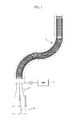
- a manipulator may include one or more variably flexible pipes 10, flexibility of which may be selectively changed.
- the manipulator may include a plurality of wires 20 that may pass through the variably flexible pipe 10 so that one end of one or more of the plural wires 20 is installed or terminates at a first end, i.e., a front end, of the variably flexible pipe 10, for example.
- One or more actuators 30 may be respectively connected to the other ends of the plural wires 20 before the plural wires 20 initially enter a second end, i.e., the trailing end, of the variably flexible pipe 10 and may be controlled to control an application of force to the wires 20 so as to selectively deform the variably flexible pipe 10.
- the manipulator may further include a pneumatic pump 40 controlling a transmitting of pneumatic pressure to an inside of a tube 14, which will be described in greater detail further below.
- FIG. 1 exemplarily illustrates three wires 20 and three actuators 30, the number of the wires 20 and the number of the actuators 30 are not limited thereto.
- embodiments are not limited to using wires, actuators, and/or pneumatic pumps, but may use components that achieve similar goals for controlling the variably flexible pipe 10, as only an example.
- the variably flexible pipe 10 may be controlled to be extended or shortened to have a designated length and, as shown in FIGS. 2 to 4 as only respective examples, may include one or more of a plurality of flap members 11, flexibility of which may be selectively controlled, a plurality of link members 12 that may form a ring shape and be sequentially provided in a longitudinal direction of the variably flexible pipe 10, and the tube 14 installed so as to cover the inner surfaces of the link members 12 and/or the outer surfaces of the flap members 11.
- an inner tube pressure of the variably flexible pipe 10, such as within an inner surface of the variably flexible pipe 10, as formed by the tube 14, may be controlled to change, such as by controlling the pneumatic pressure transmitted from the pneumatic pump 40, as only an example.
- an end cap 13 may be connected to a link member 12, e.g., on which the above-described ends of the wires 20 may be installed or terminate, so the end cap 13 may be disposed at the first end of the variably flexible pipe 10.
- each of the example flap members 11 may include plural flap parts 11a extended in one direction and a connection part 11b that may be connected to one side of each of the plural flap parts 11a.
- the connection part 11b may be bent in a ring shape so that the flap member 11 is formed in the ring shape, and may be disposed along an outer circumferential surface of at least the above-described link member 12, as only an example.
- the flap parts 11a may be extended in a direction from or toward the second end, i.e., the trailing end, of the variably flexible pipe 10 so that the flap parts 11a have a width that gradually decreases from the connection part 11b.
- the plural flap parts 11a and the connection part 11b may be formed along an outer circumference of the link member 12, but embodiments are not limited to the same.
- the flap parts 11a may be angled slightly outwardly from the connection part 11b so as to overlap an adjacent flap member 11.
- each link member 12 may include a pair of first hinge parts 12a provided at different positions along a first surface of a link member 12 facing the first end of the variably flexible pipe 10 and connected to another link member 12 adjacent to the first surface, and the pair of second hinge parts 12b of the link member 12 may be provided at different positions along a second surface of the link member 12 facing the second end of the variably flexible pipe 10 and connected to another link member 12 adjacent the second surface.
- plural link members 12 may be stacked with such respective interlocking or connected first hinge parts 12a and second hinge parts 12b of adjacent like members 12. In one or more embodiments, such interlocking or connecting of the first hinge parts 12a and second hinge parts 12b may still provide the capability for adjacent link members 12 to rotate or move relative to each other.
- first hinge parts 12a may be hinge protrusions that protrude from at least one surface of a corresponding link member 12, e.g., each protruding with in a circular shape, as only an example, and second hinge parts 12b on at least another surface of the corresponding link member 12 may be represented by hinge recesses, e.g., indented in such a circular shape, and thus multiple link members 12 may be sequentially installed so as to be rotatable with each other within at least a designated angle, for example.
- first hinge parts 12a and at least a pair of second hinge parts 12b provided on respective surfaces of one link member 12 may be provided on each surface and separated on each surface by an angle of 90° in the circumferential direction, as only an example.
- first hinge parts 12a as hinge protrusions
- second hinge parts 12b as hinge recesses
- first hinge parts 12a and the second hinge parts 12b are not limited thereto, as alternate linking elements between such sequential link members may equally be applied and/or utilized.
- the tube 14 may be formed to have a shape, e.g., a donut shaped cross section, such that an outer surface 14a along an inner circumference of the tube 14 produces a longitudinally hollow space, and such that an inner surface 14b along an outer circumference of the tube 14 longitudinally encapsulates the flap members 11 within the tube 14.
- the tube 14 may be a single longitudinal tube, as only an example.
- the tube 14 may be one or more layers of a material or different materials.
- the link members 12 and the flap members 11 may accordingly be both accommodated in the tube 14, and the tube 14 may formed of a material which is elastically deformable according to the inner pressure thereof, such as latex rubber, as only an example.
- the inner circumference of the tube 14 and/or the outer circumference of the tube 14 may be made of one or more materials that provides sufficient non-reactiveness, durability, strength, and protection for surgical procedures and for an insertion of one or more surgical tools through the tube 14 to perform a surgical act at the surgery site, as only an example.
- one or more inner pressures of such a tube 14 may be controlled to be changed according to pressure being controlled to be transmitted from the pneumatic pump 40, as only an example, so that a change in pressure is applied to one or more of the flap members 11 provided in the tube 14.
- a pressure sensitive medium may be injected into the tube 14 through the pneumatic pump 40, as only an example, so that an inner pressure of the tube 14 becomes equal to or greater than atmospheric pressure, such as shown in FIG. 5 , again as only an example.
- the pressure sensitive medium is a gas, and the gas may further be environmental or filtered air, depending on the environment the variably flexible pipe is expected to be used in.
- a compression force may selectively be caused to be applied to the flap parts 11a so as to selectively increase the frictional force sufficiently that the flap parts 11a are compressed against one or more of other flap parts 11, link members 12, and/or the connection part 11b.
- the flap parts 11a may easily slide along the surfaces of the neighboring flap parts 11a and move relative to each other. Therefore, as only an example, with such little or less frictional force, when the variably flexible pipe 10 is deformed and/or inserted in or through an opening of a body, e.g., by applying longitudinal and/or lateral forces thereto or manipulation of wires 20, the variably flexible pipe 10 may be easily deformed, e.g., by wires 20, to a desired shape and to reach a surgical site. At that point the user may desire, or there may be an automatic determination, that the pressure within the tube 14 should be caused to be decreased, increasing the frictional forces within the components of the variably flexible pipe.
- the pressure of the tube 14 may be decreased to a particular user desired, acceptable, and/or predetermined level to either substantially minimize or prevent movement between components of the variably flexible pipe, e.g., so the variably flexible pipe maintains the deformed and/or inserted shape while at the surgical site.
- air in the tube 14 may be caused to be removed, e.g., by control of the pneumatic pump 40.
- the inner pressure of the tube 14 may be decreased to below atmospheric pressure.
- exterior compressing pressure due to atmospheric pressure acting on the exterior wall of the tube 14, which then acts on the flap members 11, causes the flap parts 11a to be adhered to each other, such as shown in FIG. 6 as only an example.
- the frictional force may also be increased if the interior pressure of the tube 14 is sufficiently reduced so as to itself apply frictional force to the remaining components of the variably flexible pipe through an inward collapsing of the exterior wall of the tube 14, depending on the material of the tube 14. Accordingly, in one or more embodiments, such increasing or decreasing of frictional force between the flap parts 11a respectively suppresses or permits movement of the neighboring flap parts 11a contacting the flap parts 11a, and thus deformation of the variably flexible pipe 10 is respectively suppressed or permitted. Thus, in one or more embodiments, the suppression of movement may be variably controlled so as to permit more movement, less movement, or no movement.
- the variably flexible pipe 10 may be controlled to be in a first state in which the variably flexible pipe 10 is easily deformable, a second state in which deformation of the variably flexible pipe 10 is suppressed, or any of one or more different compression force applying states somewhere between the first and second states, according to changes of the inner pressure of the tube 14.
- FIG. 7 is an exploded perspective view of a variably flexible pipe, such as applied in a manipulator, according to one or more embodiments.
- a variably flexible pipe 10 may include first flap members 111, including applying such first flap members 111 at least onto a first of two neighboring link members 122, and second flap members 112, each including applying such second flap member 112 at least onto a second of the two neighboring link members 122.
- the first and second neighboring link member 122 may be linked through interlocking portions of each link member 122, without limiting embodiments that include other linking elements that may be applied between each link member 122, e.g., so the first and second flap members 111,112 are respectively applied to the first and second neighboring link members 122 with such other linking members therebetween.
- such one or more embodiments may include applying the first flap member 111 that includes or caused to include first flap parts 111a extended in a first direction, e.g., applying the first flap parts 111a so they are covering outer circumferential surfaces of example respective first hinge parts 122a and second hinge parts 122b connecting the two neighboring link members 122, and the second flap member 112 that includes or is caused to include second flap parts 112a extended in a second direction, e.g., opposite to the first direction, applying the second flap parts 112a so they are covering outer circumferential surfaces of the first flap parts 111a.
- the applying of the first and second flap members may be performed with the first flap member 111 and the second flap member 112 having the same or a greater length than the circumference of the link member 122, and may include applying the first and second flap members 111,112 so they are wound around two link members 122 plural times, as shown in FIG. 7 , as only an example.
- the length of the first and second flap members 111,112 may be greater than plural circumferences of the link member 122 and the applying of the first and second flap members 111,112 may include applying, e.g., winding, of the first and second flap members 111,112 over multiple neighboring link members.
- the illustrated wires 130 may act similarly to the wires 20 described with regard to FIG. 3 .
- the first flap parts 111a and the second flap parts 112a may be applied so as to be alternately disposed in the radial direction on the outer surfaces of the first hinge parts 122a and the second hinge parts 122b, such as shown in FIG. 8 as only an example.
- a tube 114 accommodates the link members 122, the first flap members 111 and, the second flap members 112.
- An inner circumferential surface 114a of the tube 114 covers the link members 122, and an outer circumferential surface 114b of the tube 114 covers the first and second flap members 111,112.
- FIG. 9 illustrates one or more embodiments where one or more components corresponding to the one or more link members 122 may not be included in the variably flexible pipe.
- one flap member 211 may be bent or applied in a longitudinal spiral so as to form a tubular shape, and wires 215 may be employed for support or to cause the flap member 211 to maintain the tubular shape.
- the aforementioned example tube 14 may also be applied in one or more parts so as to encapsulate both an outer circumference of the one flap member 211 and wires 215 and an inner circumference of the one flap member 211 and wires 215.
- one or more flap members 211 may be applied in an overlapping manner to form the same tubular shape.
- FIG. 9 illustrates one or more embodiments where flap parts 211a of the flap member 211 extend in one direction, e.g., such as the illustrated downward direction of the flap parts 211a from an upper connection part 211b of the flap member 211
- flap parts 211a of the flap member 211 extend in one direction, e.g., such as the illustrated downward direction of the flap parts 211a from an upper connection part 211b of the flap member 211
- FIG. 10 illustrates plural flap parts extending in different directions for an example one flap member, where flap parts 311a may extend from a connection part 311b of the one flap member in both illustrated upward and downward directions.
- such different extended directions of the flap part 311a may configure the variably flexible pipe so that the flap parts 311a are formed toward an inside as well as an outside of the variably flexible pipe.
- a variably flexible pipe in accordance with one or more embodiments may be applied or controlled to change frictional force between components of the variably flexible pipe, e.g., flap parts, by controlling an adjusting of an inner pressure of a tube surrounding the components of the variably flexible pipe, and thus flexibility of the variably flexible pipe is controlled to increase or decrease a capability for flexing of the variably flexible pipe.
Landscapes
- Health & Medical Sciences (AREA)
- Life Sciences & Earth Sciences (AREA)
- Engineering & Computer Science (AREA)
- Animal Behavior & Ethology (AREA)
- Biomedical Technology (AREA)
- Heart & Thoracic Surgery (AREA)
- General Health & Medical Sciences (AREA)
- Public Health (AREA)
- Veterinary Medicine (AREA)
- Surgery (AREA)
- Biophysics (AREA)
- Mechanical Engineering (AREA)
- Pulmonology (AREA)
- Anesthesiology (AREA)
- Hematology (AREA)
- Nuclear Medicine, Radiotherapy & Molecular Imaging (AREA)
- Molecular Biology (AREA)
- Pathology (AREA)
- Medical Informatics (AREA)
- General Engineering & Computer Science (AREA)
- Physics & Mathematics (AREA)
- Optics & Photonics (AREA)
- Radiology & Medical Imaging (AREA)
- Robotics (AREA)
- Manipulator (AREA)
- Surgical Instruments (AREA)
- Endoscopes (AREA)
- Actuator (AREA)
- Rigid Pipes And Flexible Pipes (AREA)
Applications Claiming Priority (1)
| Application Number | Priority Date | Filing Date | Title |
|---|---|---|---|
| KR1020120033479A KR101941569B1 (ko) | 2012-03-30 | 2012-03-30 | 가변 유연관 및 이를 갖춘 매니퓰레이터 |
Publications (3)
| Publication Number | Publication Date |
|---|---|
| EP2644083A2 true EP2644083A2 (fr) | 2013-10-02 |
| EP2644083A3 EP2644083A3 (fr) | 2014-03-19 |
| EP2644083B1 EP2644083B1 (fr) | 2017-12-06 |
Family
ID=48190700
Family Applications (1)
| Application Number | Title | Priority Date | Filing Date |
|---|---|---|---|
| EP13161961.1A Not-in-force EP2644083B1 (fr) | 2012-03-30 | 2013-04-02 | Tuyau flexible de manière variable et manipulateur |
Country Status (5)
| Country | Link |
|---|---|
| US (1) | US9937324B2 (fr) |
| EP (1) | EP2644083B1 (fr) |
| JP (1) | JP6116967B2 (fr) |
| KR (1) | KR101941569B1 (fr) |
| CN (1) | CN103356287B (fr) |
Cited By (1)
| Publication number | Priority date | Publication date | Assignee | Title |
|---|---|---|---|---|
| EP3969097A4 (fr) * | 2019-05-17 | 2023-07-05 | PAVmed Inc. | Systeme de dispositif de catheter, et méthode d'utilisation |
Families Citing this family (31)
| Publication number | Priority date | Publication date | Assignee | Title |
|---|---|---|---|---|
| CN103878784B (zh) * | 2014-03-19 | 2016-03-09 | 苏州大学 | 一种水下蛇形机器人关节模块 |
| EP3134006B1 (fr) * | 2014-04-22 | 2020-02-12 | Bio-Medical Engineering (HK) Limited | Dispositifs et systèmes robotiques chirurgicaux d'accès unique |
| WO2016118671A1 (fr) | 2015-01-20 | 2016-07-28 | Q'apel Medical, Llc | Structures tubulaires à support variable |
| WO2017041052A1 (fr) | 2015-09-03 | 2017-03-09 | Neptune Medical | Dispositif pour progression endoscopique à travers l'intestin grêle |
| CA3031943A1 (fr) * | 2016-07-27 | 2018-02-01 | Q'apel Medical, Llc | Structures tubulaires a support variable. |
| WO2018035452A1 (fr) | 2016-08-18 | 2018-02-22 | Neptune Medical | Dispositif et procédé de visualisation améliorée de l'intestin grêle |
| CN106236269B (zh) * | 2016-08-31 | 2018-09-04 | 北京术锐技术有限公司 | 一种多自由度的柔性手术工具 |
| EP3654822B1 (fr) | 2017-07-20 | 2023-11-15 | Neptune Medical Inc. | Surtube rigidifiant de manière dynamique |
| CN107997824B (zh) * | 2018-01-10 | 2019-12-13 | 北京术锐技术有限公司 | 一种可混合驱动远端结构体的柔性手术工具系统 |
| US12082791B2 (en) | 2018-01-10 | 2024-09-10 | Beijing Surgerii Robotics Company Limited | Multi-purpose flexible surgical tool system |
| US11793396B2 (en) * | 2018-01-11 | 2023-10-24 | The General Hospital Corporation | Devices, systems, and methods for advancing and positioning tethered capsule microendoscopes |
| JP7058847B2 (ja) * | 2018-05-23 | 2022-04-25 | 国立大学法人東北大学 | 線状変形装置およびグリッパ装置 |
| EP3801187B1 (fr) | 2018-05-31 | 2024-02-07 | Neptune Medical Inc. | Dispositif de visualisation améliorée de l'intestin grêle |
| EP3823711A4 (fr) | 2018-07-19 | 2022-05-18 | Neptune Medical Inc. | Structures médicales composites à rigidification dynamique |
| CN111685804B (zh) * | 2019-03-12 | 2022-05-27 | 刘永春 | 通道装置 |
| WO2020214221A1 (fr) | 2019-04-17 | 2020-10-22 | Neptune Medical Inc. | Structures médicales composites à rigidification dynamique |
| US11793392B2 (en) | 2019-04-17 | 2023-10-24 | Neptune Medical Inc. | External working channels |
| US11530621B2 (en) | 2019-10-16 | 2022-12-20 | General Electric Company | Systems and method for use in servicing a machine |
| US11744443B2 (en) | 2020-03-30 | 2023-09-05 | Neptune Medical Inc. | Layered walls for rigidizing devices |
| US11717322B2 (en) * | 2020-08-17 | 2023-08-08 | Covidien Lp | Flexible cannula having selective rigidity |
| JP2023540342A (ja) * | 2020-09-03 | 2023-09-22 | ネプチューン メディカル インク. | 動的剛性付与ガイドレールおよび使用方法 |
| US12121677B2 (en) | 2021-01-29 | 2024-10-22 | Neptune Medical Inc. | Devices and methods to prevent inadvertent motion of dynamically rigidizing apparatuses |
| CA3211622A1 (fr) | 2021-03-10 | 2022-09-15 | Neal Tanner | Commande de structures medicales robotiques, composites, rigidifiees de maniere dynamique |
| KR102457473B1 (ko) * | 2021-03-31 | 2022-10-28 | 인천대학교 산학협력단 | 파티클 유출입식 가변강성 로봇 |
| US12564312B2 (en) | 2022-04-19 | 2026-03-03 | Neptune Medical Inc. | Managing and manipulating a long length robotic endoscope |
| KR20250003955A (ko) * | 2022-04-27 | 2025-01-07 | 넵튠 메디컬 인코포레이티드 | 내시경용 위생 외장 |
| CN119907734A (zh) * | 2022-09-21 | 2025-04-29 | 三星电子株式会社 | 线驱动外骨骼操纵器以及具有其的机器人吸尘器 |
| KR20240040545A (ko) * | 2022-09-21 | 2024-03-28 | 삼성전자주식회사 | 와이어 구동 외골격 매니퓰레이터 및 이를 구비한 로봇 청소기 |
| CN116509627B (zh) * | 2023-04-23 | 2025-07-25 | 哈尔滨工业大学 | 一种耳科手术机器人内耳注射采样执行器 |
| AU2024338348A1 (en) | 2023-09-07 | 2026-03-19 | Neptune Medical Inc. | Pressure rigidization apparatuses and methods |
| WO2025072977A1 (fr) | 2023-09-28 | 2025-04-03 | Neptune Medical Inc. | Robot télescopique |
Family Cites Families (16)
| Publication number | Priority date | Publication date | Assignee | Title |
|---|---|---|---|---|
| JPS5061890A (fr) * | 1973-10-04 | 1975-05-27 | ||
| JPH045126Y2 (fr) * | 1987-09-03 | 1992-02-14 | ||
| US4815450A (en) * | 1988-02-01 | 1989-03-28 | Patel Jayendra I | Endoscope having variable flexibility |
| JPH0523291A (ja) * | 1991-07-24 | 1993-02-02 | Machida Endscope Co Ltd | 内視鏡の湾曲管 |
| DE19729499A1 (de) * | 1997-07-10 | 1999-01-14 | Friedrich Schiller Uni Jena Bu | Vorrichtung zum Erleichtern der Vorschubbewegung von flexiblen Endoskopen |
| US6974411B2 (en) * | 2000-04-03 | 2005-12-13 | Neoguide Systems, Inc. | Endoscope with single step guiding apparatus |
| US6790173B2 (en) * | 2002-06-13 | 2004-09-14 | Usgi Medical, Inc. | Shape lockable apparatus and method for advancing an instrument through unsupported anatomy |
| US7598651B2 (en) * | 2004-03-12 | 2009-10-06 | Sri International | Mechanical meta-materials |
| US7815566B2 (en) * | 2006-07-20 | 2010-10-19 | Ethicon Endo-Surgery, Inc. | Methods for stabilizing and positioning an endoscope and surgical procedures |
| KR100896750B1 (ko) | 2007-06-20 | 2009-05-11 | (주)트리플씨메디칼 | 생체 삽입용 의료기구 |
| JP2010534571A (ja) * | 2007-07-26 | 2010-11-11 | エスアールアイ インターナショナル | 選択的に硬化可能且つ能動的に操縦可能な関節動作可能装置 |
| JP4580973B2 (ja) | 2007-11-29 | 2010-11-17 | オリンパスメディカルシステムズ株式会社 | 処置具システム |
| JP2010017483A (ja) * | 2008-07-14 | 2010-01-28 | Olympus Corp | 内視鏡湾曲管及び湾曲管を有する内視鏡 |
| KR101012774B1 (ko) | 2009-06-25 | 2011-02-08 | 한국과학기술원 | 플렉시블 튜브의 형상 잠금장치 |
| JP2011067423A (ja) * | 2009-09-25 | 2011-04-07 | Olympus Corp | 内視鏡挿入部及びその製造方法 |
| JP2011194126A (ja) * | 2010-03-23 | 2011-10-06 | Fujifilm Corp | 内視鏡若しくは処置具のガイド管 |
-
2012
- 2012-03-30 KR KR1020120033479A patent/KR101941569B1/ko active Active
-
2013
- 2013-03-27 CN CN201310102192.2A patent/CN103356287B/zh not_active Expired - Fee Related
- 2013-03-28 JP JP2013070199A patent/JP6116967B2/ja not_active Expired - Fee Related
- 2013-03-29 US US13/853,267 patent/US9937324B2/en active Active
- 2013-04-02 EP EP13161961.1A patent/EP2644083B1/fr not_active Not-in-force
Non-Patent Citations (1)
| Title |
|---|
| None |
Cited By (1)
| Publication number | Priority date | Publication date | Assignee | Title |
|---|---|---|---|---|
| EP3969097A4 (fr) * | 2019-05-17 | 2023-07-05 | PAVmed Inc. | Systeme de dispositif de catheter, et méthode d'utilisation |
Also Published As
| Publication number | Publication date |
|---|---|
| KR20130111026A (ko) | 2013-10-10 |
| CN103356287A (zh) | 2013-10-23 |
| JP2013212378A (ja) | 2013-10-17 |
| CN103356287B (zh) | 2016-11-02 |
| JP6116967B2 (ja) | 2017-04-19 |
| EP2644083B1 (fr) | 2017-12-06 |
| KR101941569B1 (ko) | 2019-04-15 |
| US9937324B2 (en) | 2018-04-10 |
| US20130289478A1 (en) | 2013-10-31 |
| EP2644083A3 (fr) | 2014-03-19 |
Similar Documents
| Publication | Publication Date | Title |
|---|---|---|
| EP2644083A2 (fr) | Tuyau flexible de manière variable et manipulateur | |
| KR102164971B1 (ko) | 의료용 튜브 및 그를 구비하는 가소성 가변기구 | |
| JP7765537B2 (ja) | 構造体 | |
| JP7082052B2 (ja) | 小腸内での内視鏡前進の為の器具 | |
| JP7475858B2 (ja) | 医療用マニピュレーターの可撓チューブ及び屈曲構造体 | |
| EP3518729B1 (fr) | Tube pliable à charnière élastique améliorée | |
| US8206294B2 (en) | Surgical access device with flexible seal channel | |
| AU2015373669B2 (en) | Left atrial appendage occluder | |
| US20140188054A1 (en) | Medical tube and flexibility-variable mechanism with the same | |
| CN111727018A (zh) | 手术防尘套 | |
| EP1792561B1 (fr) | Dispositif d'endoscope automoteur | |
| JPWO2019073859A1 (ja) | 医療用マニピュレーターの可撓チューブ及び屈曲構造体 | |
| CN105246391A (zh) | 内窥镜、套管以及内窥镜系统 | |
| WO2019218946A1 (fr) | Structure de tube incurvé contrôlable | |
| CN113413200B (zh) | 一种穿刺器及腔镜机器人 | |
| CN107810335A (zh) | 致动器 | |
| JP6226359B2 (ja) | 流体圧式アクチュエータおよび湾曲駆動装置 | |
| WO2015198032A1 (fr) | Appareil destiné à fournir et à maintenir un accès à un champ opératoire | |
| JP6901800B2 (ja) | ホース構造体 | |
| JP2019528115A5 (fr) | ||
| JP2015533577A (ja) | 可撓性かつ伸縮可能な管状ガイドおよびその製造方法 | |
| EP4455490A1 (fr) | Dispositif de préhension | |
| JP5209801B2 (ja) | 内視鏡装置 | |
| JPH04194406A (ja) | アクチュエータ | |
| EP4450832A1 (fr) | Dispositif de préhension |
Legal Events
| Date | Code | Title | Description |
|---|---|---|---|
| PUAI | Public reference made under article 153(3) epc to a published international application that has entered the european phase |
Free format text: ORIGINAL CODE: 0009012 |
|
| AK | Designated contracting states |
Kind code of ref document: A2 Designated state(s): AL AT BE BG CH CY CZ DE DK EE ES FI FR GB GR HR HU IE IS IT LI LT LU LV MC MK MT NL NO PL PT RO RS SE SI SK SM TR |
|
| AX | Request for extension of the european patent |
Extension state: BA ME |
|
| PUAL | Search report despatched |
Free format text: ORIGINAL CODE: 0009013 |
|
| AK | Designated contracting states |
Kind code of ref document: A3 Designated state(s): AL AT BE BG CH CY CZ DE DK EE ES FI FR GB GR HR HU IE IS IT LI LT LU LV MC MK MT NL NO PL PT RO RS SE SI SK SM TR |
|
| AX | Request for extension of the european patent |
Extension state: BA ME |
|
| RIC1 | Information provided on ipc code assigned before grant |
Ipc: A61B 1/005 20060101AFI20140207BHEP |
|
| 17P | Request for examination filed |
Effective date: 20140918 |
|
| RBV | Designated contracting states (corrected) |
Designated state(s): AL AT BE BG CH CY CZ DE DK EE ES FI FR GB GR HR HU IE IS IT LI LT LU LV MC MK MT NL NO PL PT RO RS SE SI SK SM TR |
|
| 17Q | First examination report despatched |
Effective date: 20150211 |
|
| GRAP | Despatch of communication of intention to grant a patent |
Free format text: ORIGINAL CODE: EPIDOSNIGR1 |
|
| INTG | Intention to grant announced |
Effective date: 20170918 |
|
| GRAS | Grant fee paid |
Free format text: ORIGINAL CODE: EPIDOSNIGR3 |
|
| GRAA | (expected) grant |
Free format text: ORIGINAL CODE: 0009210 |
|
| AK | Designated contracting states |
Kind code of ref document: B1 Designated state(s): AL AT BE BG CH CY CZ DE DK EE ES FI FR GB GR HR HU IE IS IT LI LT LU LV MC MK MT NL NO PL PT RO RS SE SI SK SM TR |
|
| REG | Reference to a national code |
Ref country code: GB Ref legal event code: FG4D |
|
| REG | Reference to a national code |
Ref country code: AT Ref legal event code: REF Ref document number: 951593 Country of ref document: AT Kind code of ref document: T Effective date: 20171215 Ref country code: CH Ref legal event code: EP |
|
| REG | Reference to a national code |
Ref country code: IE Ref legal event code: FG4D |
|
| REG | Reference to a national code |
Ref country code: DE Ref legal event code: R096 Ref document number: 602013030304 Country of ref document: DE |
|
| REG | Reference to a national code |
Ref country code: NL Ref legal event code: MP Effective date: 20171206 |
|
| REG | Reference to a national code |
Ref country code: FR Ref legal event code: PLFP Year of fee payment: 6 |
|
| REG | Reference to a national code |
Ref country code: LT Ref legal event code: MG4D |
|
| PG25 | Lapsed in a contracting state [announced via postgrant information from national office to epo] |
Ref country code: SE Free format text: LAPSE BECAUSE OF FAILURE TO SUBMIT A TRANSLATION OF THE DESCRIPTION OR TO PAY THE FEE WITHIN THE PRESCRIBED TIME-LIMIT Effective date: 20171206 Ref country code: FI Free format text: LAPSE BECAUSE OF FAILURE TO SUBMIT A TRANSLATION OF THE DESCRIPTION OR TO PAY THE FEE WITHIN THE PRESCRIBED TIME-LIMIT Effective date: 20171206 Ref country code: NO Free format text: LAPSE BECAUSE OF FAILURE TO SUBMIT A TRANSLATION OF THE DESCRIPTION OR TO PAY THE FEE WITHIN THE PRESCRIBED TIME-LIMIT Effective date: 20180306 Ref country code: ES Free format text: LAPSE BECAUSE OF FAILURE TO SUBMIT A TRANSLATION OF THE DESCRIPTION OR TO PAY THE FEE WITHIN THE PRESCRIBED TIME-LIMIT Effective date: 20171206 Ref country code: LT Free format text: LAPSE BECAUSE OF FAILURE TO SUBMIT A TRANSLATION OF THE DESCRIPTION OR TO PAY THE FEE WITHIN THE PRESCRIBED TIME-LIMIT Effective date: 20171206 |
|
| REG | Reference to a national code |
Ref country code: AT Ref legal event code: MK05 Ref document number: 951593 Country of ref document: AT Kind code of ref document: T Effective date: 20171206 |
|
| PG25 | Lapsed in a contracting state [announced via postgrant information from national office to epo] |
Ref country code: HR Free format text: LAPSE BECAUSE OF FAILURE TO SUBMIT A TRANSLATION OF THE DESCRIPTION OR TO PAY THE FEE WITHIN THE PRESCRIBED TIME-LIMIT Effective date: 20171206 Ref country code: LV Free format text: LAPSE BECAUSE OF FAILURE TO SUBMIT A TRANSLATION OF THE DESCRIPTION OR TO PAY THE FEE WITHIN THE PRESCRIBED TIME-LIMIT Effective date: 20171206 Ref country code: BG Free format text: LAPSE BECAUSE OF FAILURE TO SUBMIT A TRANSLATION OF THE DESCRIPTION OR TO PAY THE FEE WITHIN THE PRESCRIBED TIME-LIMIT Effective date: 20180306 Ref country code: GR Free format text: LAPSE BECAUSE OF FAILURE TO SUBMIT A TRANSLATION OF THE DESCRIPTION OR TO PAY THE FEE WITHIN THE PRESCRIBED TIME-LIMIT Effective date: 20180307 Ref country code: RS Free format text: LAPSE BECAUSE OF FAILURE TO SUBMIT A TRANSLATION OF THE DESCRIPTION OR TO PAY THE FEE WITHIN THE PRESCRIBED TIME-LIMIT Effective date: 20171206 |
|
| PG25 | Lapsed in a contracting state [announced via postgrant information from national office to epo] |
Ref country code: NL Free format text: LAPSE BECAUSE OF FAILURE TO SUBMIT A TRANSLATION OF THE DESCRIPTION OR TO PAY THE FEE WITHIN THE PRESCRIBED TIME-LIMIT Effective date: 20171206 |
|
| PG25 | Lapsed in a contracting state [announced via postgrant information from national office to epo] |
Ref country code: CZ Free format text: LAPSE BECAUSE OF FAILURE TO SUBMIT A TRANSLATION OF THE DESCRIPTION OR TO PAY THE FEE WITHIN THE PRESCRIBED TIME-LIMIT Effective date: 20171206 Ref country code: SK Free format text: LAPSE BECAUSE OF FAILURE TO SUBMIT A TRANSLATION OF THE DESCRIPTION OR TO PAY THE FEE WITHIN THE PRESCRIBED TIME-LIMIT Effective date: 20171206 Ref country code: EE Free format text: LAPSE BECAUSE OF FAILURE TO SUBMIT A TRANSLATION OF THE DESCRIPTION OR TO PAY THE FEE WITHIN THE PRESCRIBED TIME-LIMIT Effective date: 20171206 |
|
| PG25 | Lapsed in a contracting state [announced via postgrant information from national office to epo] |
Ref country code: PL Free format text: LAPSE BECAUSE OF FAILURE TO SUBMIT A TRANSLATION OF THE DESCRIPTION OR TO PAY THE FEE WITHIN THE PRESCRIBED TIME-LIMIT Effective date: 20171206 Ref country code: RO Free format text: LAPSE BECAUSE OF FAILURE TO SUBMIT A TRANSLATION OF THE DESCRIPTION OR TO PAY THE FEE WITHIN THE PRESCRIBED TIME-LIMIT Effective date: 20171206 Ref country code: IT Free format text: LAPSE BECAUSE OF FAILURE TO SUBMIT A TRANSLATION OF THE DESCRIPTION OR TO PAY THE FEE WITHIN THE PRESCRIBED TIME-LIMIT Effective date: 20171206 Ref country code: AT Free format text: LAPSE BECAUSE OF FAILURE TO SUBMIT A TRANSLATION OF THE DESCRIPTION OR TO PAY THE FEE WITHIN THE PRESCRIBED TIME-LIMIT Effective date: 20171206 Ref country code: SM Free format text: LAPSE BECAUSE OF FAILURE TO SUBMIT A TRANSLATION OF THE DESCRIPTION OR TO PAY THE FEE WITHIN THE PRESCRIBED TIME-LIMIT Effective date: 20171206 |
|
| REG | Reference to a national code |
Ref country code: DE Ref legal event code: R097 Ref document number: 602013030304 Country of ref document: DE |
|
| PLBE | No opposition filed within time limit |
Free format text: ORIGINAL CODE: 0009261 |
|
| STAA | Information on the status of an ep patent application or granted ep patent |
Free format text: STATUS: NO OPPOSITION FILED WITHIN TIME LIMIT |
|
| 26N | No opposition filed |
Effective date: 20180907 |
|
| PG25 | Lapsed in a contracting state [announced via postgrant information from national office to epo] |
Ref country code: DK Free format text: LAPSE BECAUSE OF FAILURE TO SUBMIT A TRANSLATION OF THE DESCRIPTION OR TO PAY THE FEE WITHIN THE PRESCRIBED TIME-LIMIT Effective date: 20171206 Ref country code: SI Free format text: LAPSE BECAUSE OF FAILURE TO SUBMIT A TRANSLATION OF THE DESCRIPTION OR TO PAY THE FEE WITHIN THE PRESCRIBED TIME-LIMIT Effective date: 20171206 Ref country code: MC Free format text: LAPSE BECAUSE OF FAILURE TO SUBMIT A TRANSLATION OF THE DESCRIPTION OR TO PAY THE FEE WITHIN THE PRESCRIBED TIME-LIMIT Effective date: 20171206 |
|
| REG | Reference to a national code |
Ref country code: CH Ref legal event code: PL |
|
| REG | Reference to a national code |
Ref country code: BE Ref legal event code: MM Effective date: 20180430 |
|
| REG | Reference to a national code |
Ref country code: IE Ref legal event code: MM4A |
|
| PG25 | Lapsed in a contracting state [announced via postgrant information from national office to epo] |
Ref country code: LU Free format text: LAPSE BECAUSE OF NON-PAYMENT OF DUE FEES Effective date: 20180402 |
|
| PG25 | Lapsed in a contracting state [announced via postgrant information from national office to epo] |
Ref country code: BE Free format text: LAPSE BECAUSE OF NON-PAYMENT OF DUE FEES Effective date: 20180430 Ref country code: CH Free format text: LAPSE BECAUSE OF NON-PAYMENT OF DUE FEES Effective date: 20180430 Ref country code: LI Free format text: LAPSE BECAUSE OF NON-PAYMENT OF DUE FEES Effective date: 20180430 |
|
| PG25 | Lapsed in a contracting state [announced via postgrant information from national office to epo] |
Ref country code: IE Free format text: LAPSE BECAUSE OF NON-PAYMENT OF DUE FEES Effective date: 20180402 |
|
| PG25 | Lapsed in a contracting state [announced via postgrant information from national office to epo] |
Ref country code: MT Free format text: LAPSE BECAUSE OF NON-PAYMENT OF DUE FEES Effective date: 20180402 |
|
| PG25 | Lapsed in a contracting state [announced via postgrant information from national office to epo] |
Ref country code: TR Free format text: LAPSE BECAUSE OF FAILURE TO SUBMIT A TRANSLATION OF THE DESCRIPTION OR TO PAY THE FEE WITHIN THE PRESCRIBED TIME-LIMIT Effective date: 20171206 |
|
| PG25 | Lapsed in a contracting state [announced via postgrant information from national office to epo] |
Ref country code: PT Free format text: LAPSE BECAUSE OF FAILURE TO SUBMIT A TRANSLATION OF THE DESCRIPTION OR TO PAY THE FEE WITHIN THE PRESCRIBED TIME-LIMIT Effective date: 20171206 Ref country code: HU Free format text: LAPSE BECAUSE OF FAILURE TO SUBMIT A TRANSLATION OF THE DESCRIPTION OR TO PAY THE FEE WITHIN THE PRESCRIBED TIME-LIMIT; INVALID AB INITIO Effective date: 20130402 |
|
| PG25 | Lapsed in a contracting state [announced via postgrant information from national office to epo] |
Ref country code: CY Free format text: LAPSE BECAUSE OF FAILURE TO SUBMIT A TRANSLATION OF THE DESCRIPTION OR TO PAY THE FEE WITHIN THE PRESCRIBED TIME-LIMIT Effective date: 20171206 Ref country code: MK Free format text: LAPSE BECAUSE OF NON-PAYMENT OF DUE FEES Effective date: 20171206 |
|
| PG25 | Lapsed in a contracting state [announced via postgrant information from national office to epo] |
Ref country code: AL Free format text: LAPSE BECAUSE OF FAILURE TO SUBMIT A TRANSLATION OF THE DESCRIPTION OR TO PAY THE FEE WITHIN THE PRESCRIBED TIME-LIMIT Effective date: 20171206 Ref country code: IS Free format text: LAPSE BECAUSE OF FAILURE TO SUBMIT A TRANSLATION OF THE DESCRIPTION OR TO PAY THE FEE WITHIN THE PRESCRIBED TIME-LIMIT Effective date: 20180406 |
|
| PGFP | Annual fee paid to national office [announced via postgrant information from national office to epo] |
Ref country code: FR Payment date: 20230321 Year of fee payment: 11 |
|
| PGFP | Annual fee paid to national office [announced via postgrant information from national office to epo] |
Ref country code: GB Payment date: 20230320 Year of fee payment: 11 |
|
| PGFP | Annual fee paid to national office [announced via postgrant information from national office to epo] |
Ref country code: DE Payment date: 20230320 Year of fee payment: 11 |
|
| REG | Reference to a national code |
Ref country code: DE Ref legal event code: R119 Ref document number: 602013030304 Country of ref document: DE |
|
| GBPC | Gb: european patent ceased through non-payment of renewal fee |
Effective date: 20240402 |
|
| PG25 | Lapsed in a contracting state [announced via postgrant information from national office to epo] |
Ref country code: DE Free format text: LAPSE BECAUSE OF NON-PAYMENT OF DUE FEES Effective date: 20241105 |
|
| PG25 | Lapsed in a contracting state [announced via postgrant information from national office to epo] |
Ref country code: GB Free format text: LAPSE BECAUSE OF NON-PAYMENT OF DUE FEES Effective date: 20240402 |
|
| PG25 | Lapsed in a contracting state [announced via postgrant information from national office to epo] |
Ref country code: FR Free format text: LAPSE BECAUSE OF NON-PAYMENT OF DUE FEES Effective date: 20240430 |
|
| PG25 | Lapsed in a contracting state [announced via postgrant information from national office to epo] |
Ref country code: GB Free format text: LAPSE BECAUSE OF NON-PAYMENT OF DUE FEES Effective date: 20240402 Ref country code: FR Free format text: LAPSE BECAUSE OF NON-PAYMENT OF DUE FEES Effective date: 20240430 Ref country code: DE Free format text: LAPSE BECAUSE OF NON-PAYMENT OF DUE FEES Effective date: 20241105 |