EP2644383A2 - Élément d'impression pour une machine destinée à fabriquer des produits en forme de tiges de l'industrie de traitement du tabac - Google Patents
Élément d'impression pour une machine destinée à fabriquer des produits en forme de tiges de l'industrie de traitement du tabac Download PDFInfo
- Publication number
- EP2644383A2 EP2644383A2 EP12193332.9A EP12193332A EP2644383A2 EP 2644383 A2 EP2644383 A2 EP 2644383A2 EP 12193332 A EP12193332 A EP 12193332A EP 2644383 A2 EP2644383 A2 EP 2644383A2
- Authority
- EP
- European Patent Office
- Prior art keywords
- ink
- printing unit
- unit according
- cannula
- printing
- Prior art date
- Legal status (The legal status is an assumption and is not a legal conclusion. Google has not performed a legal analysis and makes no representation as to the accuracy of the status listed.)
- Granted
Links
- 241000208125 Nicotiana Species 0.000 title claims description 6
- 235000002637 Nicotiana tabacum Nutrition 0.000 title claims description 6
- 238000004519 manufacturing process Methods 0.000 title claims description 5
- 238000010079 rubber tapping Methods 0.000 claims description 39
- 238000005520 cutting process Methods 0.000 claims description 13
- 239000010409 thin film Substances 0.000 claims description 13
- 238000012545 processing Methods 0.000 claims description 5
- 239000003973 paint Substances 0.000 claims description 4
- 238000009826 distribution Methods 0.000 description 9
- 238000000034 method Methods 0.000 description 9
- 230000008569 process Effects 0.000 description 9
- 239000000463 material Substances 0.000 description 4
- 239000000203 mixture Substances 0.000 description 4
- 230000009172 bursting Effects 0.000 description 3
- 238000011109 contamination Methods 0.000 description 3
- 238000011161 development Methods 0.000 description 3
- 239000002245 particle Substances 0.000 description 3
- 230000008901 benefit Effects 0.000 description 2
- 230000006835 compression Effects 0.000 description 2
- 238000007906 compression Methods 0.000 description 2
- 230000008878 coupling Effects 0.000 description 2
- 238000010168 coupling process Methods 0.000 description 2
- 238000005859 coupling reaction Methods 0.000 description 2
- 238000013461 design Methods 0.000 description 2
- 230000005484 gravity Effects 0.000 description 2
- 238000003860 storage Methods 0.000 description 2
- 208000005156 Dehydration Diseases 0.000 description 1
- 230000009471 action Effects 0.000 description 1
- 230000015572 biosynthetic process Effects 0.000 description 1
- 238000006243 chemical reaction Methods 0.000 description 1
- 235000019504 cigarettes Nutrition 0.000 description 1
- 239000003086 colorant Substances 0.000 description 1
- 238000005056 compaction Methods 0.000 description 1
- 230000018044 dehydration Effects 0.000 description 1
- 238000006297 dehydration reaction Methods 0.000 description 1
- 230000001419 dependent effect Effects 0.000 description 1
- 230000000694 effects Effects 0.000 description 1
- 238000000605 extraction Methods 0.000 description 1
- 239000011796 hollow space material Substances 0.000 description 1
- 238000003032 molecular docking Methods 0.000 description 1
- 230000009467 reduction Effects 0.000 description 1
- 238000007789 sealing Methods 0.000 description 1
- 238000012546 transfer Methods 0.000 description 1
- 238000011144 upstream manufacturing Methods 0.000 description 1
Images



Classifications
-
- B—PERFORMING OPERATIONS; TRANSPORTING
- B41—PRINTING; LINING MACHINES; TYPEWRITERS; STAMPS
- B41F—PRINTING MACHINES OR PRESSES
- B41F31/00—Inking arrangements or devices
- B41F31/02—Ducts, containers, supply or metering devices
- B41F31/08—Ducts, containers, supply or metering devices with ink ejecting means, e.g. pumps, nozzles
-
- A—HUMAN NECESSITIES
- A24—TOBACCO; CIGARS; CIGARETTES; SIMULATED SMOKING DEVICES; SMOKERS' REQUISITES
- A24C—MACHINES FOR MAKING CIGARS OR CIGARETTES
- A24C5/00—Making cigarettes; Making tipping materials for, or attaching filters or mouthpieces to, cigars or cigarettes
- A24C5/38—Machines combined with printing devices
-
- B—PERFORMING OPERATIONS; TRANSPORTING
- B41—PRINTING; LINING MACHINES; TYPEWRITERS; STAMPS
- B41P—INDEXING SCHEME RELATING TO PRINTING, LINING MACHINES, TYPEWRITERS, AND TO STAMPS
- B41P2217/00—Printing machines of special types or for particular purposes
- B41P2217/50—Printing presses for particular purposes
Definitions
- the invention relates to a printing unit for a machine for the production of products of the tobacco processing industry having the features of the preamble of claim 1 or 10 and a swap body for use in a printing unit having the features of the preamble of claim 18.
- a generic printing unit including a machine for the production of products of the tobacco processing industry is for example from DE 10 2007 030 197 A1 known.
- the function of the printing unit is to provide a wrapping strip of the products with a mark, which may consist eg in the name of the manufacturer or the type designation of the products.
- the markings can be printed both in the form of pictorial representations of symbols as well as in the form of short letter sequences in one or more colors.
- the printing unit comprises a plurality of rollers of different function, such as a pressure roller with one or more punches, a color distribution roller and a color pickup roller. The rollers are each in line contact with each other and are driven individually or rotationally together.
- the ink is applied from a paint reservoir to the ink fountain roller and then distributed by the ink distribution roller uniformly over the circumference and along the longitudinal axis.
- the ink distribution roller is driven in an oscillating manner in the direction of its longitudinal axis.
- the ink is applied to one or more punches of the pressure roller, which finally the markings imprint on the wrapping strip.
- the pressure roller is passed before applying the ink on the stamp with these on a brush, which cleans the stamp for a clean print image of the ink of the previous printing process.
- the printing ink itself is a high-viscosity or high-pasty printing ink with a viscosity of 10 to 30 Pas, and therefore corresponds more to a tough paste. Due to this high viscosity, the ink generally has the problem of trapped air, which does not escape automatically even after a longer service life of the printing ink.
- the color with the air bubbles is supplied to the printing unit, it is unavoidable that the printing marks in the area of the air pockets are weaker because the punches in this area are not provided with a sufficient amount of printing ink. For a clean print image, it is therefore necessary that the ink is as free of air bubbles as possible.
- a so-called color cart with a container is used in practice, which regularly has to be refilled with the ink manually. Since the printing ink is very viscous, the printing ink must be filled very carefully and slowly, so that no additional air bubbles are formed.
- the object of the invention is therefore to provide a printing unit with an improved print quality and easier to handle refilling of the ink and to simplify the refilling process in itself.
- the invention proposes a printing unit with the features of claim 1 or claim 10 and a removable container with the features of claim 18.
- a nozzle unit be provided in the conveying path of the printing ink from the ink reservoir to the ink receiving roller, in which the printing ink is compressed and released via a nozzle opening into an intermediate store.
- the compression of the ink leads to a compression of the air contained in the air bubbles, which then expands upon exiting the nozzle opening and is released suddenly by bursting of air pockets.
- the air pockets can be continuously removed from the ink by a comparatively simple device in the conveying path. In this case, only a pressure increase of the air present in the air inclusions is used to remove the air pockets, so that the air bubbles burst practically automatically.
- the Printing ink is directed into a buffer in which the released air can be removed and does not mix again with the ink. Since the air pockets are released automatically due to the inventive solution, when refilling the ink basically less care must be taken that no air pockets arise, so that the refilling is easier to handle and can be performed faster. Furthermore, the print quality is improved due to the smaller number of air pockets and the resulting more homogeneous ink.
- the cache is closed to the environment. This prevents contamination of the ink by externally introduced particles.
- the ink is thereby exposed in the buffer only a limited volume of air, so that a possible chemical reaction of the ink at the surface with the components of the air can be reduced.
- the temporary storage has a flow connection to the environment, which can be closed by a valve.
- the intermediate store can be fluidly connected to the environment at least temporarily to equalize the pressure so that the pressure build-up generated by the released air inclusions can be compensated.
- the nozzle unit is arranged between the ink reservoir and the first feed device supplying the ink to the ink receiving roller.
- the printing ink is thereby supplied to the feeding device, which supplies the printing ink to the ink receiving roller, free of air entrapment, so that the ink is conveyed in the best possible way already in the feeder and finally an applicator for applying the ink is supplied to the ink pickup roller.
- a second feeding device which feeds the printing ink from the ink reservoir to the nozzle unit.
- the second feeder serves to pressurize the ink in front of the nozzle unit and allows active and e.g. also controlled supply of the ink to the nozzle unit.
- the first feed device can be activated as a function of the second feed device and / or vice versa.
- a dependent control can be prevented that accumulates the ink in the conveying path from the ink reservoir to the ink pickup roller or that the flow breaks or the buffer runs empty.
- the intermediate store is a funnel which is oriented upward with the larger opening and into which the printing ink is introduced via the nozzle opening from above.
- the funnel serves in this case as a collector, in which the ink automatically slips under the action of gravity in the opening of smaller diameter.
- the nozzle opening is arranged such that the printing ink emerges along a wall of the intermediate store.
- the ink collects on the wall, while the air bubbles burst on the surface, so that finally on the wall exclusively air-tight printing ink is present.
- the adhesion forces acting between the wall and the ink are deliberately used, which do not act in the region of the air inclusions of the printing ink, so that preferably air-tight printing ink adheres to the wall and slides downwards.
- the printing unit has a connection and the ink reservoir is formed by a swap body, which can be connected via a detachable connection via the connection to the printing unit.
- the ink reservoir itself can be replaced and connected directly to the printing unit, so that the previously required manual refilling of the color car is eliminated.
- Such a solution is also independent of the nozzle unit an advantageous further development of the prior art invention.
- connection is a piercing cannula
- the interchangeable container has a thin layer, which is pierced for connecting the interchangeable container to the printing unit of the piercing cannula.
- the empty swap body can be easily removed from the puncture cannula for changing and a new filled swap body can be attached to the puncture cannula without the need for tools or special craftsmanship skills and knowledge.
- the swap body is thereby simultaneously held close to the printing unit by the pierced Thin layer sealing the puncture cannula includes.
- the puncture cannula may also have a sealed puncture point on its end face, so that the thin layer is pierced, without a cutout being punched out of the thin layer, which could clog the puncture cannula and in particular the nozzle unit.
- the puncture tip is closed by a closure wall set back into the piercing cannula and formed by an annular cutting edge extending from the closure wall to the end of the piercing cannula, which has an end-side edge surface which is in a direction to the piercing direction sloping plane runs.
- the proposed solution allows a puncture process with a very small amount of force.
- the piercing cannula thereby punctures during the tapping operation due to the smaller cutting surface, and thereby realized on the surface of the thin film related higher cutting forces faster and immediately after contact with the thin film, so that the tapping cannula in a significantly shorter time compared to the thin film and the container is fixed against lateral slipping.
- the swap body has slopes, in particular at the edge of the thin layer, where the puncture point can slide off laterally under unfavorable circumstances during the tapping process.
- the cutting edge is interrupted at a location of the closure wall. Due to the interruption of the cutting edge, the material of the opening is not completely punched out, but instead only an open one Ring. At the end of the tapping process remains through the interruption, a section which acts as a tab around which the punched circle of the thin film is pivoted. As a result, a connection between the punched out material of the thin film and the rest of the thin layer is deliberately maintained, so that the punched-out material does not fall into the swap body and under unfavorable circumstances can lead to disturbances in the supply of the printing ink.
- the piercing cannula can have a lateral opening arranged in the wall of the piercing cannula, so that the inflow opening in the piercing cannula can be functionally separated from the piercing side.
- an electromagnet is provided with which the tapping cannula is movable out of the interchangeable container.
- an electromagnet By using an electromagnet, the movement of the piercing cannula out of the swap body can be very easily controlled and effected, wherein the electromagnet in particular allows a movement of the piercing cannula without a special mechanical coupling to the electromagnet.
- the tapping cannula can be held and moved by the electromagnet solely by way of magnetic forces, wherein the tapping cannula is preferably arranged in a movable assembly with a punch which is preferably designed to be magnetic for transmitting the tensile forces exerted by the adjacent electromagnet.
- the electromagnet is coupled to a drive device.
- the electromagnet serves in this case to a coupling of the piercing cannula, while the drive device finally causes the movement of the docking cannula coupled to the electromagnet.
- drive means are preferably linear actuators, such as pneumatic cylinder, used, the linear drive movement is transmitted without further over- or reduction and deflection to the tapping cannula.
- an interchangeable container for use in a printing unit is proposed to solve the problem, having a connection pin, in which the thin film is arranged, and with which the interchangeable container is fixable in an opening of the printing unit.
- the connecting pin may have a profiling, which secures the swap body in the opening of the printing unit by a clamping connection against the withdrawal direction.
- FIG. 1 is a printing unit to recognize, which is known in the basic structure and, for example, from DE 10 2007 030 197 A1 is known.
- the DE 10 2007 030 197 A1 is expressly added to the disclosure content of this application in terms of the printing unit and the parent machine.
- the printing unit to be recognized comprises a color pickup roller 1, a color distribution roller 2 and a pressure roller 3, which abut each other in a line contact.
- an application device 4 is arranged for an ink, which is directed with an outlet opening 7 on the circumference of the ink receiving roller 1.
- the ink applied to the ink receiving roller 1 is transferred to the ink distribution roller 2 via the line contact.
- the ink distribution roller 2 is driven during the rotational movement to an oscillating transverse movement in the direction of its longitudinal axis, so that the ink taken over by the ink receiving roller 1 is distributed transversely to the rotational movement on the circumference of the ink distribution roller 2.
- the ink distribution roller 2 has a plurality of grooves in the circumferential direction, which distribute the ink across the rotational movement.
- the pressure roller 3 has a plurality of punches 5, which are raised from the circumference of the pressure roller 3 and profiled according to the mark to be applied, and with which the pressure roller 3 comes to rest on a guided over wrapping strip 6 for the products of the tobacco processing industry.
- the products can be eg cigarettes, Cigarillos or the like.
- the pressure roller 3 comes with the punches 5 before contact with the wrapping strip 6 in contact with the ink distribution roller 2, wherein the punches 5 are wetted with the ink.
- the applicator 4 is shown simplified with the supply of ink.
- the ink is supplied from a paint reservoir 10 formed by a swap body 41 having a cylindrical cavity 13 and a piston 12 guided in the cavity 13.
- the swap body 41 is in the FIG. 3 shown enlarged and arranged with the cylindrical cavity 13 in a horizontal orientation on the printing unit.
- the interchangeable container 41 has on its front side a closed by a thin film 20 prior to attachment to the printing unit opening.
- the swap body 41 is replaceable as a pre-filled ink reservoir 10, so that the previously required Um colllvorgang the ink is eliminated.
- a piercing cannula 21 with an oblique piercing point 22 closed in the direction of piercing is provided, which is pierced by the thin layer 20 into a pre-volume 18 of the cavity 13 when the interchangeable container 41 is connected.
- this includes the tapping cannula 21, so that the interchangeable container 41 is connected both releasably and sealed to the printing unit.
- the tapping cannula 21 itself forms a connection 14 or is part of a connection 14, via which the printing ink can be fed to a nozzle unit 15 when the piston 12 is actuated.
- the piercing cannula 21 has an opening 23 arranged in the lateral wall, which opens into a throughflow channel 24 provided in the piercing cannula 21. Since the tapping point 22 is closed and the opening 23 is disposed in the side wall, firstly, the thin film 20 is prevented from being punched out, and secondly, any possibly dissolved particles are prevented from entering the flow channel 24.
- the opening 23 is preferably arranged on the upper side of the tapping cannula 21, so that particles which have fallen down, which have fallen down from the thin layer 20, can not enter the opening 23.
- the piercing tip 21 is formed as an inclined surface which forms a tip with the upper wall side of the piercing cannula 21. Due to the orientation of the oblique surface on the underside of the piercing cannula 21, the thin layer 20 is displaced from the tip downwards, ie to the side opposite the opening 23, so that the thin layer 20 consciously away from the inflow region of the opening 23 is displaced.
- the thin layer 20 is arranged in the end face of a connecting pin 25, which forms the pre-volume 18 upstream of the hollow space 13, into which the piercing cannula 21 protrudes.
- the pre-volume 18 is formed as a smaller cylindrical cavity, which adjoins the actual cavity 13, so that the tapping cannula 21 is fluidically connected to the cavity 13, without thereby reducing the stroke of the piston 12.
- the connecting pin 21 is provided on its outer side with a profiling 28 formed by ribs, by means of which the connecting pin 25 and thus also the swap body 41 itself by a clamping connection in an opening 27 of a wall 26 of the printing unit can be fixed.
- the proposed design of the interchangeable container 41 and the piercing cannula 21 allows an exchange of the ink reservoir 10, without the operator being in contact with the ink, and without having to transfer the ink. Furthermore, the swap body 41 pierced by the formation of the piercing cannula 21 and a corresponding dimensioning of the wall thickness of the thin film 20 with a reasonable applied force, without the tapping cannula 21 can enforce this.
- the swap bodies 41 can be procured and stored in a larger number, without the ink is thereby subject to the risk of dehydration. Furthermore, the refilling and storage of the ink can be done without a possible contact of the ink to the environment.
- the nozzle unit 15 has a narrowing flow channel 16 and an outlet opening 17, which is arranged on a wall of a buffer 9.
- the outlet opening can lie in the wall itself or be arranged at a small distance to this, so that the exiting ink comes to rest directly or after overcoming a short gap on the wall of the buffer 9.
- the buffer 9 is designed as a funnel with the larger opening facing upwards, so that the ink emerging from the outlet opening 17 automatically slides down to the smaller opening of the funnel.
- the funnel is closed, so that no foreign bodies can penetrate.
- a valve 19 is provided on the funnel, which closes an opening or conduit through which existing overpressure 19 can be reduced when the valve is open.
- the advantage of the proposed solution is generally to be seen in the fact that the air is compressed in the air pockets still present in the narrowing flow channel 16, the ink itself is not compressed, since it can be regarded as incompressible.
- the air pockets burst spontaneously and suddenly, with the result that, on the wall of the funnel, the ink finally flows downwards substantially without or at least with fewer air inclusions. It is important that the mixture of the ink and the air bubbles from the outlet opening 17 is released into a buffer 9, in which the bursting air pockets are separated from the ink so that the air released does not mix again with the ink.
- the pressure in the buffer 9 be less than the pressure in the trapped air, which can be solved particularly easily by compressing the air in the trapped air in the nozzle unit 15 from the ambient pressure and in the buffer 9, there is at least about the same pressure as in the environment, so that the air in the air pockets in the nozzle unit 15 is automatically compressed beyond the pressure prevailing in the buffer 9.
- the ink then sinks under the force of gravity in the funnel-shaped buffer 9 down to a first feeding device 8 with a gear pump 11, which supplies the now formed free of trapped air ink of the applicator 4. Since the ink slides on the wall of the buffer 9 on a relatively large surface down, the remaining air pockets are previously released at the wall of the funnel by bursting. This is due to the fact that the ink flows down in a thin layer due to the large surface of the wall, the air pockets separated only by a thin film of the ink from the environment, which can be easily destroyed by the internal pressure of the air bubbles.
- the ink of the nozzle unit 15 is actively supplied by means of a second supply means, which is formed in this case by the piston 12, whereby the pressure generated in the nozzle unit 15 of the air present in the air inclusions changed and in particular can be increased.
- the second feed device can preferably be activated as a function of the first feed device and / or vice versa, so that a continuous and constant stream of printing ink can be realized. In particular, this can be prevented that the flow of ink is interrupted, or accumulates the ink in the buffer 9.
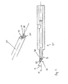
- FIG. 4 is a further development of the piercing cannula 21 in sectional view and seen obliquely from the front in the view.
- the tapping cannula 21 also has a closed tapping point 22.
- the tapping point 22 is here closed by a closure wall 30, which is set back into the tapping cannula 21, so that an annular cutting edge 31 results.
- the cutting edge 31 merges into the closure wall 30 at one point, ie it is interrupted by the closure wall 30, as can be seen in the upper representation at the top of the tapping cannula 21 and in the lower representation at the bottom of the tapping cannula 21.
- the piercing point 22 is formed by a bevel on the face side, so that the edge surface 29 of the cutting edge 31 extends in a plane B, which is aligned at an angle A to the piercing direction X of the tapping cannula 21.
- the thin layer 20 is punched by means of the cutting edge 31, starting from a puncture point annular, wherein a portion in the interruption of the cutting edge 31 is deliberately not punched, which then forms a connection between the punched material and the rest of the thin film.
- the punched out part of the thin film is then displaced to the end of the tapping movement of the tapping cannula 21 and does not fall uncontrollably into the interchangeable container 41 due to the still existing connection.
- the applied tapping forces can be reduced, or the cutting forces acting on the thin layer can be increased, so that the tapping process can be made substantially more reliable.
- this can reduce the likelihood that the tapping cannula 21 slides off laterally on the swap body 41.
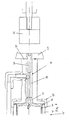
- FIG. 5 is a further development of the printing unit with an electromagnet 32 and a linear drive device 33 can be seen, with the replacement process of the interchangeable container 41 is further simplified.
- the electromagnet 32 can be moved linearly in the direction of the longitudinal axis of the tapping cannula 21 via the drive device 33, which is arranged here in an assembly 40.
- the assembly 40 with the tapping cannula 21 is followed on the left side by a container 35 with the interchangeable container 41 arranged therein.
- FIG. 6 is an enlarged section of the FIG. 5 shown.
- the container 35 has a tube 42 which is open on the left side and closed by a flap 38. On the front side, the tube 42 is closed by a flange assembly 43 with a ring seal 36.
- the assembly 40 includes beside the puncture cannula 21 a tube 39 and a punch 37, which is sealed in the inserted position of the piercing cannula 21 via a seal 34 on the end face of the flange assembly 43, so that the container 35 with the therein arranged swap body 41 at one end on the flap 38th and is sealed at its other end on the flange assembly 43 and the punch 37.
- the ink can not escape, which is advantageous in terms of a clean workplace and a low probability of contamination of the products.
- the drive device 33 is activated and energized the electromagnet 32 and moved against the punch 37.
- the punch 37 is magnetically formed and is thereby held on the energized electromagnet 32.
- the direction of movement of the drive means 33 is reversed and the electromagnet 32 is pulled away from the container 35 together with the assembly 40. Since the interchangeable container 41 rests against the flange assembly 43 during the withdrawal movement of the assembly 40, the tapping cannula 21 is pulled out of the interchangeable container 41.
- the electromagnet 32 driven by the drive device 33 pushes the assembly 40 with the puncture cannula 21 in the direction of the container 35 into the flange subassembly 43 until the puncture cannula 21 with the puncture tip 22 strikes the thin layer 20 of the Swap body 41 meets.
- the interchangeable container 41 is supported on the flap 38, so that the puncture cannula 21 is pierced with the puncture point 22 into the interchangeable container 41.
- the swap body 41 can be changed without the person handling the ink in contact can come. Further, the ink can not leak through the sealed space in the container 35 and the flange assembly 43, and it can also be discharged from the interchangeable container 41 under control of a suitable pressure generating means.
- the advantage of the electromagnet 32 used is that the assembly 40 can be pulled out by the acting magnetic force, without the need for a positive connection is required.
- the electromagnet 32 serves to transmit the tensile force, while the actual extraction movement is effected via the drive device 33.
Landscapes
- Inking, Control Or Cleaning Of Printing Machines (AREA)
- Ink Jet (AREA)
- Manufacturing Of Cigar And Cigarette Tobacco (AREA)
- Coating Apparatus (AREA)
Priority Applications (2)
| Application Number | Priority Date | Filing Date | Title |
|---|---|---|---|
| EP17179302.9A EP3254853A1 (fr) | 2012-03-26 | 2012-11-20 | Unité d'impression pour une machine destinée à fabriquer des produits de l'industrie de traitement du tabac |
| PL12193332T PL2644383T3 (pl) | 2012-03-26 | 2012-11-20 | Zespół drukujący do maszyny wytwarzającej produkty przemysłu tytoniowego |
Applications Claiming Priority (1)
| Application Number | Priority Date | Filing Date | Title |
|---|---|---|---|
| DE102012204768A DE102012204768A1 (de) | 2012-03-26 | 2012-03-26 | Druckwerk für eine Maschine zur Herstellung von Produkten der Tabak verarbeitenden Industrie |
Related Child Applications (2)
| Application Number | Title | Priority Date | Filing Date |
|---|---|---|---|
| EP17179302.9A Division-Into EP3254853A1 (fr) | 2012-03-26 | 2012-11-20 | Unité d'impression pour une machine destinée à fabriquer des produits de l'industrie de traitement du tabac |
| EP17179302.9A Division EP3254853A1 (fr) | 2012-03-26 | 2012-11-20 | Unité d'impression pour une machine destinée à fabriquer des produits de l'industrie de traitement du tabac |
Publications (3)
| Publication Number | Publication Date |
|---|---|
| EP2644383A2 true EP2644383A2 (fr) | 2013-10-02 |
| EP2644383A3 EP2644383A3 (fr) | 2014-08-20 |
| EP2644383B1 EP2644383B1 (fr) | 2017-10-04 |
Family
ID=47278141
Family Applications (2)
| Application Number | Title | Priority Date | Filing Date |
|---|---|---|---|
| EP12193332.9A Not-in-force EP2644383B1 (fr) | 2012-03-26 | 2012-11-20 | Élément d'impression pour une machine destinée à fabriquer des produits en forme de tiges de l'industrie de traitement du tabac |
| EP17179302.9A Withdrawn EP3254853A1 (fr) | 2012-03-26 | 2012-11-20 | Unité d'impression pour une machine destinée à fabriquer des produits de l'industrie de traitement du tabac |
Family Applications After (1)
| Application Number | Title | Priority Date | Filing Date |
|---|---|---|---|
| EP17179302.9A Withdrawn EP3254853A1 (fr) | 2012-03-26 | 2012-11-20 | Unité d'impression pour une machine destinée à fabriquer des produits de l'industrie de traitement du tabac |
Country Status (4)
| Country | Link |
|---|---|
| EP (2) | EP2644383B1 (fr) |
| CN (1) | CN103358682B (fr) |
| DE (1) | DE102012204768A1 (fr) |
| PL (1) | PL2644383T3 (fr) |
Families Citing this family (2)
| Publication number | Priority date | Publication date | Assignee | Title |
|---|---|---|---|---|
| CN103640329B (zh) * | 2013-11-28 | 2016-04-27 | 弘益泰克自动化设备(惠州)有限公司 | 一种锡膏供给装置 |
| CN113928021B (zh) * | 2021-09-22 | 2023-07-07 | 中山市施之美科技有限公司 | 一种墨盒组件及其喷墨打印机 |
Citations (1)
| Publication number | Priority date | Publication date | Assignee | Title |
|---|---|---|---|---|
| DE102007030197A1 (de) | 2007-06-27 | 2009-01-02 | Hauni Maschinenbau Ag | Druckwerk einer Maschine der Tabak verarbeitenden Industrie |
Family Cites Families (7)
| Publication number | Priority date | Publication date | Assignee | Title |
|---|---|---|---|---|
| DE937935C (de) * | 1954-03-07 | 1956-01-19 | Gustav Mahr | Tintenpatrone zum Nachfuellen eines Fuellfederhalters |
| IT1133265B (it) * | 1980-04-03 | 1986-07-09 | Gd Spa | Dispositivo distributore per materiali vischiosi |
| DE3014904A1 (de) * | 1980-04-18 | 1981-11-05 | Hauni-Werke Körber & Co KG, 2050 Hamburg | Verfahren und anordnung zum uebertragen von farbe aus einem handelsueblichen farbbehaelter auf einen zigarettenpapierstreifen |
| DE19648567A1 (de) * | 1996-11-23 | 1998-05-28 | Decoufle Sarl | Anordnung zum Zuführen von fließfähiger Druckfarbe zu einem Druckwerk |
| TW474869B (en) * | 1998-12-24 | 2002-02-01 | Japan Tobacco Inc | Printing device for printing a roll paper to be supplied to a cigarette manufacturing machine |
| EP1415805A1 (fr) * | 2002-10-28 | 2004-05-06 | Hauni Maschinenbau AG | Groupe d'impression avec unité d'éaquilibrage de température |
| DE102005035701A1 (de) * | 2005-07-27 | 2007-02-08 | Hauni Maschinenbau Ag | Druckwerk der Tabak verarbeitenden Industrie |
-
2012
- 2012-03-26 DE DE102012204768A patent/DE102012204768A1/de not_active Withdrawn
- 2012-11-20 EP EP12193332.9A patent/EP2644383B1/fr not_active Not-in-force
- 2012-11-20 PL PL12193332T patent/PL2644383T3/pl unknown
- 2012-11-20 EP EP17179302.9A patent/EP3254853A1/fr not_active Withdrawn
-
2013
- 2013-03-26 CN CN201310099092.9A patent/CN103358682B/zh not_active Expired - Fee Related
Patent Citations (1)
| Publication number | Priority date | Publication date | Assignee | Title |
|---|---|---|---|---|
| DE102007030197A1 (de) | 2007-06-27 | 2009-01-02 | Hauni Maschinenbau Ag | Druckwerk einer Maschine der Tabak verarbeitenden Industrie |
Also Published As
| Publication number | Publication date |
|---|---|
| PL2644383T3 (pl) | 2018-02-28 |
| CN103358682A (zh) | 2013-10-23 |
| EP2644383B1 (fr) | 2017-10-04 |
| CN103358682B (zh) | 2017-05-24 |
| EP2644383A3 (fr) | 2014-08-20 |
| EP3254853A1 (fr) | 2017-12-13 |
| DE102012204768A1 (de) | 2013-09-26 |
Similar Documents
| Publication | Publication Date | Title |
|---|---|---|
| DE69104367T2 (de) | Ausgabeverfahren und -vorrichtung, insbesondere für dichtungs-/klebemittel. | |
| DE2261734C3 (de) | Tintenstrahlaufzeichnungsgerät | |
| DE3033352C2 (fr) | ||
| DE3203014A1 (de) | Tintenstrahldrucker und tintentropfenausstossvorrichtung sowie verfahren zur verhinderung ihres verstopfens durch tinte | |
| DE3112490C2 (de) | Vorrichtung zum selbsttätigen Zuführen von Druckfarbe zu einer Druckvorrichtung | |
| DE1201041B (de) | Schneckenstrangpresse fuer plastische Massen, z. B. thermoplastische Kunststoffe | |
| DE19705006A1 (de) | Vorrichtung zum Zuführen und Absaugen von Farbe in Druckmaschinen | |
| EP2183056A1 (fr) | Dispositif d'application de matériaux de recouvrement liquides | |
| EP2644383B1 (fr) | Élément d'impression pour une machine destinée à fabriquer des produits en forme de tiges de l'industrie de traitement du tabac | |
| DE3911694A1 (de) | Vorrichtung zur zufuhr von harzmaterial zu einer kunstharz-formteilpresse | |
| DE102021109816A1 (de) | Verfahren zum Entleeren von viskosem Material aus einer beidseitig offenen Kartusche sowie hierfür geeignete Entleer-Vorrichtung | |
| WO1999004975A2 (fr) | Procede et dispositif pour recouvrir et nettoyer les buses d'une tete d'impression a l'encre | |
| DE2258017A1 (de) | Geraet zum auftragen einer fluessigkeit | |
| EP2468106A1 (fr) | Dispositif et procédé de répartition d'air résiduel dans des masses pâteuses, notamment pour la fabrication de saucisses | |
| DE202023107584U1 (de) | Abgabemechanismus einer Luftansaugnadel und Ventilaustragsmechanismus | |
| DE2223817A1 (de) | Vorrichtung zum aufbringen von klebstoff | |
| DE2710481A1 (de) | Verfahren und vorrichtung zum vakuum- bzw. unterdruckformen einer giessform | |
| EP1834778A2 (fr) | Kit destiné à la formation d'un système d'alimentation en encre pour machines d'impression | |
| DE60300466T2 (de) | Tintenzufuhrvorrichtung und Tintenzufuhrverfahren für Schablonendrucker und Tintenbehälter | |
| EP2091737B1 (fr) | Procédé de nettoyage ainsi que dispositif de nettoyage pour une surface cylindrique d'une machine d'impression | |
| EP0484705A1 (fr) | Dispositif pour le remplissage de saucisses | |
| DE3824335A1 (de) | Tintenstrahldrucker und verfahren zum schutz der tinte eines tintenstrahldruckers gegen eintrocknen | |
| DE2746382A1 (de) | Tintenstrahl-schreibsystem | |
| DE2724320A1 (de) | Vorrichtung zur mischung von konzentrat und wasser | |
| DE2936056C2 (de) | Dosiervorrichtung für Flüssigkeiten |
Legal Events
| Date | Code | Title | Description |
|---|---|---|---|
| PUAI | Public reference made under article 153(3) epc to a published international application that has entered the european phase |
Free format text: ORIGINAL CODE: 0009012 |
|
| AK | Designated contracting states |
Kind code of ref document: A2 Designated state(s): AL AT BE BG CH CY CZ DE DK EE ES FI FR GB GR HR HU IE IS IT LI LT LU LV MC MK MT NL NO PL PT RO RS SE SI SK SM TR |
|
| AX | Request for extension of the european patent |
Extension state: BA ME |
|
| RIN1 | Information on inventor provided before grant (corrected) |
Inventor name: GOLZ, PETER Inventor name: FEIERABEND, ANDREAS Inventor name: SOLTOW, RALF Inventor name: KOCH, FRANZ-PETER Inventor name: SCHMICK, CLEMENS Inventor name: HARTMANN, FRANZ Inventor name: MASCH, SIMON Inventor name: SPILL, MATTHIAS |
|
| PUAL | Search report despatched |
Free format text: ORIGINAL CODE: 0009013 |
|
| AK | Designated contracting states |
Kind code of ref document: A3 Designated state(s): AL AT BE BG CH CY CZ DE DK EE ES FI FR GB GR HR HU IE IS IT LI LT LU LV MC MK MT NL NO PL PT RO RS SE SI SK SM TR |
|
| AX | Request for extension of the european patent |
Extension state: BA ME |
|
| RIC1 | Information provided on ipc code assigned before grant |
Ipc: A24C 5/38 20060101ALI20140715BHEP Ipc: B41F 31/08 20060101AFI20140715BHEP |
|
| 17P | Request for examination filed |
Effective date: 20150129 |
|
| RBV | Designated contracting states (corrected) |
Designated state(s): AL AT BE BG CH CY CZ DE DK EE ES FI FR GB GR HR HU IE IS IT LI LT LU LV MC MK MT NL NO PL PT RO RS SE SI SK SM TR |
|
| RAP1 | Party data changed (applicant data changed or rights of an application transferred) |
Owner name: HAUNI MASCHINENBAU GMBH |
|
| GRAP | Despatch of communication of intention to grant a patent |
Free format text: ORIGINAL CODE: EPIDOSNIGR1 |
|
| INTG | Intention to grant announced |
Effective date: 20170420 |
|
| GRAA | (expected) grant |
Free format text: ORIGINAL CODE: 0009210 |
|
| GRAS | Grant fee paid |
Free format text: ORIGINAL CODE: EPIDOSNIGR3 |
|
| AK | Designated contracting states |
Kind code of ref document: B1 Designated state(s): AL AT BE BG CH CY CZ DE DK EE ES FI FR GB GR HR HU IE IS IT LI LT LU LV MC MK MT NL NO PL PT RO RS SE SI SK SM TR |
|
| REG | Reference to a national code |
Ref country code: GB Ref legal event code: FG4D Free format text: NOT ENGLISH |
|
| REG | Reference to a national code |
Ref country code: CH Ref legal event code: EP |
|
| REG | Reference to a national code |
Ref country code: AT Ref legal event code: REF Ref document number: 933621 Country of ref document: AT Kind code of ref document: T Effective date: 20171015 |
|
| REG | Reference to a national code |
Ref country code: IE Ref legal event code: FG4D Free format text: LANGUAGE OF EP DOCUMENT: GERMAN |
|
| REG | Reference to a national code |
Ref country code: DE Ref legal event code: R096 Ref document number: 502012011376 Country of ref document: DE |
|
| REG | Reference to a national code |
Ref country code: NL Ref legal event code: FP |
|
| REG | Reference to a national code |
Ref country code: LT Ref legal event code: MG4D |
|
| PG25 | Lapsed in a contracting state [announced via postgrant information from national office to epo] |
Ref country code: ES Free format text: LAPSE BECAUSE OF FAILURE TO SUBMIT A TRANSLATION OF THE DESCRIPTION OR TO PAY THE FEE WITHIN THE PRESCRIBED TIME-LIMIT Effective date: 20171004 Ref country code: FI Free format text: LAPSE BECAUSE OF FAILURE TO SUBMIT A TRANSLATION OF THE DESCRIPTION OR TO PAY THE FEE WITHIN THE PRESCRIBED TIME-LIMIT Effective date: 20171004 Ref country code: LT Free format text: LAPSE BECAUSE OF FAILURE TO SUBMIT A TRANSLATION OF THE DESCRIPTION OR TO PAY THE FEE WITHIN THE PRESCRIBED TIME-LIMIT Effective date: 20171004 Ref country code: SE Free format text: LAPSE BECAUSE OF FAILURE TO SUBMIT A TRANSLATION OF THE DESCRIPTION OR TO PAY THE FEE WITHIN THE PRESCRIBED TIME-LIMIT Effective date: 20171004 Ref country code: NO Free format text: LAPSE BECAUSE OF FAILURE TO SUBMIT A TRANSLATION OF THE DESCRIPTION OR TO PAY THE FEE WITHIN THE PRESCRIBED TIME-LIMIT Effective date: 20180104 |
|
| PG25 | Lapsed in a contracting state [announced via postgrant information from national office to epo] |
Ref country code: HR Free format text: LAPSE BECAUSE OF FAILURE TO SUBMIT A TRANSLATION OF THE DESCRIPTION OR TO PAY THE FEE WITHIN THE PRESCRIBED TIME-LIMIT Effective date: 20171004 Ref country code: RS Free format text: LAPSE BECAUSE OF FAILURE TO SUBMIT A TRANSLATION OF THE DESCRIPTION OR TO PAY THE FEE WITHIN THE PRESCRIBED TIME-LIMIT Effective date: 20171004 Ref country code: GR Free format text: LAPSE BECAUSE OF FAILURE TO SUBMIT A TRANSLATION OF THE DESCRIPTION OR TO PAY THE FEE WITHIN THE PRESCRIBED TIME-LIMIT Effective date: 20180105 Ref country code: BG Free format text: LAPSE BECAUSE OF FAILURE TO SUBMIT A TRANSLATION OF THE DESCRIPTION OR TO PAY THE FEE WITHIN THE PRESCRIBED TIME-LIMIT Effective date: 20180104 Ref country code: LV Free format text: LAPSE BECAUSE OF FAILURE TO SUBMIT A TRANSLATION OF THE DESCRIPTION OR TO PAY THE FEE WITHIN THE PRESCRIBED TIME-LIMIT Effective date: 20171004 Ref country code: IS Free format text: LAPSE BECAUSE OF FAILURE TO SUBMIT A TRANSLATION OF THE DESCRIPTION OR TO PAY THE FEE WITHIN THE PRESCRIBED TIME-LIMIT Effective date: 20180204 |
|
| REG | Reference to a national code |
Ref country code: DE Ref legal event code: R097 Ref document number: 502012011376 Country of ref document: DE |
|
| PG25 | Lapsed in a contracting state [announced via postgrant information from national office to epo] |
Ref country code: CH Free format text: LAPSE BECAUSE OF NON-PAYMENT OF DUE FEES Effective date: 20171130 Ref country code: EE Free format text: LAPSE BECAUSE OF FAILURE TO SUBMIT A TRANSLATION OF THE DESCRIPTION OR TO PAY THE FEE WITHIN THE PRESCRIBED TIME-LIMIT Effective date: 20171004 Ref country code: LI Free format text: LAPSE BECAUSE OF NON-PAYMENT OF DUE FEES Effective date: 20171130 Ref country code: SK Free format text: LAPSE BECAUSE OF FAILURE TO SUBMIT A TRANSLATION OF THE DESCRIPTION OR TO PAY THE FEE WITHIN THE PRESCRIBED TIME-LIMIT Effective date: 20171004 Ref country code: DK Free format text: LAPSE BECAUSE OF FAILURE TO SUBMIT A TRANSLATION OF THE DESCRIPTION OR TO PAY THE FEE WITHIN THE PRESCRIBED TIME-LIMIT Effective date: 20171004 Ref country code: MC Free format text: LAPSE BECAUSE OF FAILURE TO SUBMIT A TRANSLATION OF THE DESCRIPTION OR TO PAY THE FEE WITHIN THE PRESCRIBED TIME-LIMIT Effective date: 20171004 Ref country code: CZ Free format text: LAPSE BECAUSE OF FAILURE TO SUBMIT A TRANSLATION OF THE DESCRIPTION OR TO PAY THE FEE WITHIN THE PRESCRIBED TIME-LIMIT Effective date: 20171004 |
|
| PLBE | No opposition filed within time limit |
Free format text: ORIGINAL CODE: 0009261 |
|
| STAA | Information on the status of an ep patent application or granted ep patent |
Free format text: STATUS: NO OPPOSITION FILED WITHIN TIME LIMIT |
|
| PG25 | Lapsed in a contracting state [announced via postgrant information from national office to epo] |
Ref country code: SM Free format text: LAPSE BECAUSE OF FAILURE TO SUBMIT A TRANSLATION OF THE DESCRIPTION OR TO PAY THE FEE WITHIN THE PRESCRIBED TIME-LIMIT Effective date: 20171004 Ref country code: RO Free format text: LAPSE BECAUSE OF FAILURE TO SUBMIT A TRANSLATION OF THE DESCRIPTION OR TO PAY THE FEE WITHIN THE PRESCRIBED TIME-LIMIT Effective date: 20171004 Ref country code: LU Free format text: LAPSE BECAUSE OF NON-PAYMENT OF DUE FEES Effective date: 20171120 |
|
| REG | Reference to a national code |
Ref country code: FR Ref legal event code: ST Effective date: 20180731 Ref country code: BE Ref legal event code: MM Effective date: 20171130 |
|
| REG | Reference to a national code |
Ref country code: IE Ref legal event code: MM4A |
|
| 26N | No opposition filed |
Effective date: 20180705 |
|
| GBPC | Gb: european patent ceased through non-payment of renewal fee |
Effective date: 20180104 |
|
| PG25 | Lapsed in a contracting state [announced via postgrant information from national office to epo] |
Ref country code: MT Free format text: LAPSE BECAUSE OF FAILURE TO SUBMIT A TRANSLATION OF THE DESCRIPTION OR TO PAY THE FEE WITHIN THE PRESCRIBED TIME-LIMIT Effective date: 20171004 |
|
| PG25 | Lapsed in a contracting state [announced via postgrant information from national office to epo] |
Ref country code: FR Free format text: LAPSE BECAUSE OF NON-PAYMENT OF DUE FEES Effective date: 20171204 Ref country code: IE Free format text: LAPSE BECAUSE OF NON-PAYMENT OF DUE FEES Effective date: 20171120 |
|
| PG25 | Lapsed in a contracting state [announced via postgrant information from national office to epo] |
Ref country code: SI Free format text: LAPSE BECAUSE OF FAILURE TO SUBMIT A TRANSLATION OF THE DESCRIPTION OR TO PAY THE FEE WITHIN THE PRESCRIBED TIME-LIMIT Effective date: 20171004 Ref country code: GB Free format text: LAPSE BECAUSE OF NON-PAYMENT OF DUE FEES Effective date: 20180104 Ref country code: BE Free format text: LAPSE BECAUSE OF NON-PAYMENT OF DUE FEES Effective date: 20171130 |
|
| PGFP | Annual fee paid to national office [announced via postgrant information from national office to epo] |
Ref country code: NL Payment date: 20181123 Year of fee payment: 7 |
|
| REG | Reference to a national code |
Ref country code: AT Ref legal event code: MM01 Ref document number: 933621 Country of ref document: AT Kind code of ref document: T Effective date: 20171120 |
|
| PG25 | Lapsed in a contracting state [announced via postgrant information from national office to epo] |
Ref country code: AT Free format text: LAPSE BECAUSE OF NON-PAYMENT OF DUE FEES Effective date: 20171120 |
|
| PGFP | Annual fee paid to national office [announced via postgrant information from national office to epo] |
Ref country code: PL Payment date: 20181024 Year of fee payment: 7 Ref country code: DE Payment date: 20181203 Year of fee payment: 7 |
|
| PGFP | Annual fee paid to national office [announced via postgrant information from national office to epo] |
Ref country code: IT Payment date: 20181130 Year of fee payment: 7 |
|
| PG25 | Lapsed in a contracting state [announced via postgrant information from national office to epo] |
Ref country code: HU Free format text: LAPSE BECAUSE OF FAILURE TO SUBMIT A TRANSLATION OF THE DESCRIPTION OR TO PAY THE FEE WITHIN THE PRESCRIBED TIME-LIMIT; INVALID AB INITIO Effective date: 20121120 |
|
| PG25 | Lapsed in a contracting state [announced via postgrant information from national office to epo] |
Ref country code: CY Free format text: LAPSE BECAUSE OF NON-PAYMENT OF DUE FEES Effective date: 20171004 |
|
| PG25 | Lapsed in a contracting state [announced via postgrant information from national office to epo] |
Ref country code: MK Free format text: LAPSE BECAUSE OF FAILURE TO SUBMIT A TRANSLATION OF THE DESCRIPTION OR TO PAY THE FEE WITHIN THE PRESCRIBED TIME-LIMIT Effective date: 20171004 |
|
| PG25 | Lapsed in a contracting state [announced via postgrant information from national office to epo] |
Ref country code: TR Free format text: LAPSE BECAUSE OF FAILURE TO SUBMIT A TRANSLATION OF THE DESCRIPTION OR TO PAY THE FEE WITHIN THE PRESCRIBED TIME-LIMIT Effective date: 20171004 |
|
| PG25 | Lapsed in a contracting state [announced via postgrant information from national office to epo] |
Ref country code: PT Free format text: LAPSE BECAUSE OF FAILURE TO SUBMIT A TRANSLATION OF THE DESCRIPTION OR TO PAY THE FEE WITHIN THE PRESCRIBED TIME-LIMIT Effective date: 20171004 |
|
| REG | Reference to a national code |
Ref country code: DE Ref legal event code: R119 Ref document number: 502012011376 Country of ref document: DE |
|
| REG | Reference to a national code |
Ref country code: NL Ref legal event code: MM Effective date: 20191201 |
|
| PG25 | Lapsed in a contracting state [announced via postgrant information from national office to epo] |
Ref country code: AL Free format text: LAPSE BECAUSE OF FAILURE TO SUBMIT A TRANSLATION OF THE DESCRIPTION OR TO PAY THE FEE WITHIN THE PRESCRIBED TIME-LIMIT Effective date: 20171004 |
|
| PG25 | Lapsed in a contracting state [announced via postgrant information from national office to epo] |
Ref country code: NL Free format text: LAPSE BECAUSE OF NON-PAYMENT OF DUE FEES Effective date: 20191201 |
|
| PG25 | Lapsed in a contracting state [announced via postgrant information from national office to epo] |
Ref country code: DE Free format text: LAPSE BECAUSE OF NON-PAYMENT OF DUE FEES Effective date: 20200603 Ref country code: IT Free format text: LAPSE BECAUSE OF NON-PAYMENT OF DUE FEES Effective date: 20191120 |
|
| PG25 | Lapsed in a contracting state [announced via postgrant information from national office to epo] |
Ref country code: PL Free format text: LAPSE BECAUSE OF NON-PAYMENT OF DUE FEES Effective date: 20191120 |