EP2644419A1 - Boîtier de réception et régulation de la température d'un dispositif électronique et véhicule doté de ce boîtier - Google Patents
Boîtier de réception et régulation de la température d'un dispositif électronique et véhicule doté de ce boîtier Download PDFInfo
- Publication number
- EP2644419A1 EP2644419A1 EP20130161180 EP13161180A EP2644419A1 EP 2644419 A1 EP2644419 A1 EP 2644419A1 EP 20130161180 EP20130161180 EP 20130161180 EP 13161180 A EP13161180 A EP 13161180A EP 2644419 A1 EP2644419 A1 EP 2644419A1
- Authority
- EP
- European Patent Office
- Prior art keywords
- housing
- air
- vehicle
- electronic device
- temperature
- Prior art date
- Legal status (The legal status is an assumption and is not a legal conclusion. Google has not performed a legal analysis and makes no representation as to the accuracy of the status listed.)
- Granted
Links
Images



Classifications
-
- B—PERFORMING OPERATIONS; TRANSPORTING
- B60—VEHICLES IN GENERAL
- B60H—ARRANGEMENTS OF HEATING, COOLING, VENTILATING OR OTHER AIR-TREATING DEVICES SPECIALLY ADAPTED FOR PASSENGER OR GOODS SPACES OF VEHICLES
- B60H1/00—Heating, cooling or ventilating devices
- B60H1/24—Ventilating devices where the heating or cooling is irrelevant
-
- B—PERFORMING OPERATIONS; TRANSPORTING
- B60—VEHICLES IN GENERAL
- B60H—ARRANGEMENTS OF HEATING, COOLING, VENTILATING OR OTHER AIR-TREATING DEVICES SPECIALLY ADAPTED FOR PASSENGER OR GOODS SPACES OF VEHICLES
- B60H1/00—Heating, cooling or ventilating devices
- B60H1/00271—HVAC devices specially adapted for particular vehicle parts or components and being connected to the vehicle HVAC unit
-
- B—PERFORMING OPERATIONS; TRANSPORTING
- B60—VEHICLES IN GENERAL
- B60H—ARRANGEMENTS OF HEATING, COOLING, VENTILATING OR OTHER AIR-TREATING DEVICES SPECIALLY ADAPTED FOR PASSENGER OR GOODS SPACES OF VEHICLES
- B60H1/00—Heating, cooling or ventilating devices
-
- B—PERFORMING OPERATIONS; TRANSPORTING
- B60—VEHICLES IN GENERAL
- B60H—ARRANGEMENTS OF HEATING, COOLING, VENTILATING OR OTHER AIR-TREATING DEVICES SPECIALLY ADAPTED FOR PASSENGER OR GOODS SPACES OF VEHICLES
- B60H1/00—Heating, cooling or ventilating devices
- B60H1/34—Nozzles; Air-diffusers
-
- H—ELECTRICITY
- H05—ELECTRIC TECHNIQUES NOT OTHERWISE PROVIDED FOR
- H05K—PRINTED CIRCUITS; CASINGS OR CONSTRUCTIONAL DETAILS OF ELECTRIC APPARATUS; MANUFACTURE OF ASSEMBLAGES OF ELECTRICAL COMPONENTS
- H05K7/00—Constructional details common to different types of electric apparatus
- H05K7/20—Modifications to facilitate cooling, ventilating, or heating
- H05K7/20845—Modifications to facilitate cooling, ventilating, or heating for automotive electronic casings
- H05K7/20863—Forced ventilation, e.g. on heat dissipaters coupled to components
-
- B—PERFORMING OPERATIONS; TRANSPORTING
- B60—VEHICLES IN GENERAL
- B60H—ARRANGEMENTS OF HEATING, COOLING, VENTILATING OR OTHER AIR-TREATING DEVICES SPECIALLY ADAPTED FOR PASSENGER OR GOODS SPACES OF VEHICLES
- B60H1/00—Heating, cooling or ventilating devices
- B60H1/00271—HVAC devices specially adapted for particular vehicle parts or components and being connected to the vehicle HVAC unit
- B60H2001/003—Component temperature regulation using an air flow
-
- B—PERFORMING OPERATIONS; TRANSPORTING
- B60—VEHICLES IN GENERAL
- B60H—ARRANGEMENTS OF HEATING, COOLING, VENTILATING OR OTHER AIR-TREATING DEVICES SPECIALLY ADAPTED FOR PASSENGER OR GOODS SPACES OF VEHICLES
- B60H1/00—Heating, cooling or ventilating devices
- B60H1/00507—Details, e.g. mounting arrangements, desaeration devices
- B60H2001/00614—Cooling of electronic units in air stream
Definitions
- the present invention relates to a housing for receiving and temperature control (temperature) of an electronic device and a vehicle with this housing, wherein the housing is arranged in particular at a predetermined position in a passenger compartment of the vehicle.
- Operating temperature is meant a temperature range in which the electronic device optimally, i. H. without harm and works with high efficiency.
- a reliable functioning is essential in an electronic device which is arranged in the passenger compartment of a motor vehicle and which serves driving safety.
- a temperature control device must do this even in extreme situations, e.g. As in summer, when the vehicle is exposed to the sun for a long time and the temperature of the passenger compartment is very high, ensure.
- claim 1 comprises a vehicle, a passenger compartment, an air conditioning system, which is adapted to tempered air flows in the To produce a passenger compartment, a housing, which is arranged at a predetermined location in the passenger compartment, adapted to receive an electronic device and at least one air inlet opening and at least one air outlet opening for flowing through a tempered air flow of the air conditioner comprises.
- the vehicle is characterized in that a temperature control of the electronic device is performed exclusively by the temperature regulation by means of the air conditioner.
- the temperature control is carried out exclusively either by cooling or heating air streams from and through the air conditioning system or by regulating the flow rate or air mass per unit time of these air streams, which by convection transport heat to or from the electronic device.
- a tempered, ie cooled or heated, air flow is preferably passed through the housing.
- 'regulation' is to be understood here as a generic term both for a control and for a control (ie a manual specification of a temperature).
- present invention can be incorporated into the development phase of a new car or used to retrofit an existing vehicle.
- the effective temperature control of the electronic device is thus effected by the interaction of (a) the air flows supplied by the air conditioning system and tempered by them, (b) the housing which directs the air flow through and / or around the electronic device, and (c) the Arrangement (position and orientation) of the electronic device, through which the regulation is carried out with a high degree of efficiency and with the least possible utilization of vehicle resources.
- the term "exclusively" here means, in particular, that the housing does not comprise regulating means such as flaps or diaphragms or the like. Therefore, the feature means that, a temperature regulation of the electronic device takes place exclusively by the temperature regulation by means of the air conditioning system, that the housing is not a part of the air conditioning system, but the object that is tempered by it.
- an air duct of the air conditioner with the housing is firmly connected, while according to a further advantageous embodiment of the present invention (claim 3), the housing is flown from the outside of the air flow.
- the advantage of the first advantageous embodiment lies in the higher efficiency of cooling / heating, since the Entire (100%) airflow exiting the air duct enters the housing and is available for regulating the temperature of the electronic device.
- the advantage of the second advantageous embodiment is a constructive and thus financial, because the duct must not extend in this case to the housing, between the end of the duct (the exit point of the air flow into the passenger compartment) and the housing is a distance.
- the end of the air duct is provided with a suitable nozzle which determines (a) the direction and (b) the flow characteristic of the air flow so that the position (by (a)) of the housing within the passenger compartment is flexible and the efficiency of the cooling / Heating can be optimized (eg by (b)).
- a suitable nozzle which determines (a) the direction and (b) the flow characteristic of the air flow so that the position (by (a)) of the housing within the passenger compartment is flexible and the efficiency of the cooling / Heating can be optimized (eg by (b)).
- factors that affect the efficiency of the cooling / heating z. Temperature, airflow flow rate, and housing design (see below).
- a further advantageous embodiment of the present invention is the predetermined position in an A-pillar of the vehicle.
- the advantage of this position is that usually already air ducts are provided which extend to the lateral ends of the dashboard and its cover and usually direct the air flow to the windshield and / or a side window of the vehicle .
- This advantage is particularly for the above-mentioned second advantageous embodiment (claim 3) to fruition, because the existing A-pillar must be changed only either so that the housing can be included therein (the above-mentioned development phase), or against a specific exchanged for this purpose A-pillar (the above-mentioned retrofitting).
- the A-pillar can be prepared for optional, later installation of the housing according to the invention.
- the air conditioning must either not be changed or only by replacing the nozzles for better flow to the housing. Furthermore, in the first advantageous embodiment (claim 2) only a suitable extension of the air duct is required. As a result, a retrofit of a vehicle with the housing according to the invention or a conversion of a vehicle to the vehicle according to the invention is very inexpensive. As explained below, it is possible that the electronic device, an LCD or a includes other display. In such a case, the position of the housing in the A-pillar is advantageous because the information displayed thereon can be recognized by both the driver and the passenger. In which of the two A-pillars the housing is arranged, also depends on the electronic device itself.
- the housing is preferably located in the right A-pillar because the blind spot on the left side of the vehicle is light can be viewed by turning the head.
- a corresponding recess may be present or produced, into which the housing is fitted, or the housing may to a certain extent be formed as an A-pillar, ie have a depression in which the electronic device can be placed.
- claim 5 is the predetermined position on the dashboard of the vehicle. This position is also advantageously in the immediate vicinity of normally existing air ducts, so that the here to the advantageous embodiment according to claim 4 of the present invention has also validity here.
- the housing is integrally connected to an element of the vehicle, while according to a further advantageous embodiment of the present invention (claim 7) is detachably connected to an element of the vehicle.
- An 'element' of the vehicle according to the invention is preferably an aperture of an A-pillar or the dashboard cover of the vehicle.
- the phrase 'the housing is integrally connected to an element of the vehicle' (claim 6) according to the invention is to be understood as opposed to 'releasable' (claim 7). That is, the housing and the member are integrally connected with each other, for example, by an injection molding method or the like.
- the housing is releasably connected to the element when either (a) it can be nondestructively attached to the element by means of a suitable tool and removed / disassembled from the element, for example for the purpose of repair or maintenance, or (b ) pluggable, latchable, or the like can be attached to the element.
- the housing is fastened to the dashboard cover approximately above the center console and an electrical device with a display is accommodated in it, it is advantageous if the connection is rotatable, so that the display can be aligned either with the driver or with the passenger. In an advantageous embodiment, in this case, for example, by rotating the housing, automatically different air channels are selected, so that the housing is optimally flowed in any position (situation of claim 2).
- an internal temperature of the housing is a control variable for adjusting the operating temperature.
- the defined in claim 1 temperature regulation is thus concretized in particular as a regulation in the z. B. the flow velocity or the temperature of the air flow are manipulated variables.
- the goal is to regulate the temperature of the electronic device, with the housing in which the electronic device is housed being used as the 'flow guide'. Since the temperature of the housing of several factors such as the position of the housing in the passenger compartment, the weather conditions, ie in particular the sunlight, the insulation and surface coating of the housing depends, for reliable temperature regulation preferably the internal temperature of the housing is detected and as a controlled variable of the control loop used.
- a temperature sensor required for this purpose is arranged in the flow shadow of the electronic device so that incorrect measurements by hysteresis are avoided as far as possible (the sensor can possibly be cooled / heated faster in the air flow than the electronic device).
- the sensor is arranged at a particularly temperature-sensitive location of the electronic device.
- the electronic device is an indirect vision system, which is arranged in the field of view of a driver of the vehicle.
- the indirect vision system is suitable for replacing or supplementing a conventional rearview mirror.
- the indirect vision system is connected to at least one in-vehicle or onboard camera which images a predetermined field of view. If the indirect vision system is connected to a plurality of such cameras, it is advantageously switchable either between the individual fields of view, or the multiple fields of view are displayed side by side on a display of the indirect vision system.
- the electronic device may be a navigation device or in addition to the indirect vision system.
- the at least one air outlet opening is arranged so that the air flow flowing out of the housing flows against at least one pane of the vehicle.
- the air flow is passed through the housing and deflected in it, so that it impinges on the disc.
- the disc is in particular the windscreen and / or a side window of the vehicle.
- the air flow, which is passed into the housing is heated more than the air flow is directed directly into the interior of the passenger compartment without flowing through the housing. Since the temperature of the air flow is selected as high as possible (not higher than the upper limit of the operating temperature range) in order to ensure the fastest possible reaching of the operating temperature, the temperature of the air flow after passing through the housing is still higher than that despite heat emission to the electronic device Air flow temperature for general heating of the passenger compartment.
- This relatively high temperature of the air stream, which is directed to a disc of the vehicle has the advantage that the view through the respective impinged disc is improved very quickly.
- claim 11 is an air duct of the air conditioner with the at least one air inlet opening fluidly connectable.
- the air duct extends to the housing and is sealed to this.
- the housing preferably has only one air inlet opening whose size is matched to the size of the end of the air channel.
- the at least one air inlet opening has a cross section which decreases in the interior of the housing.
- This has the advantage that the largest possible part of the air flow is "captured” and directed into the interior of the housing (funnel effect), wherein the cross section is advantageously designed so that an air blade laminar flow is formed in the interior of the housing.
- the at least one air inlet opening can be oriented with respect to the overall housing such that the air flow optimally flows around the electronic device or that the air flow is preferably directed toward temperature-sensitive sections of the electronic device.
- a plurality of air inlet openings along an edge of the housing are arranged.
- the electronic device is firmly integrated in the housing, while according to a further advantageous embodiment of the present invention (claim 15), the housing is designed as a docking station and the electronic device is a mobile device, which can be coupled with the docking station.
- the removability The mobile electronic device means interchangeability and theft protection. Interchangeability, in turn, means that the system can be used modularly.
- several people who use the vehicle alternately may each use their personal electronic device containing personal data and settings.
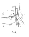
- FIGS. 1 and 2 each show a housing 12 mounted in an A pillar 10 of a vehicle (only the area around the lower end of the A pillar is shown) in which an electronic device (not shown) is received.
- FIGS. 3 and 4 each show the attached to a dashboard cover 14 housing 12th
- FIGS. 1 and 3 each show an air duct 16 as part of an air conditioning system (not shown) of the vehicle, which is fluidly connected to the housing 12.
- the air flow introduced into the housing 12 via the air duct 16 flows into the housing 12 at an air inlet opening 18 and leaves the housing 12 through a plurality of air outlet openings 20 FIGS. 1 and 3 can be seen, the air flows toward one of the windshield 22 ( Fig. 1 ) and on the other in the direction of a side window 24 through the air outlet openings 20 from the housing 12.
- the housing 12 is integrally connected to the dashboard cover 14.
- FIGS. 2 and 4 each show an embodiment in which there is a gap between the air duct 16 and the housing 12, that is, the housing 12 is flown by the air flow; the air flow is not coupled directly into the housing 12 as in the case of the FIGS. 1 and 3 illustrated embodiment.
- the air stream originates from nozzles 26 which form the ends of the air duct 16 or a plurality of air ducts 16 of the air conditioning system and direct the air flow in a defined manner to the housing 12.
- Air inlet openings 28 are in Fig. 2 along a part of the circumference of the housing 12 and in Fig. 4 on side surfaces 30 (only visible on one side surface).
- the housing 12 in the embodiment of Fig. 4 not integrally connected to the dashboard cover 14, but releasably attached to it.
- none of the housings 12 according to the embodiments 1 to 4 is provided with a means capable of providing a contribution to the temperature regulation of the electronic device.
Landscapes
- Physics & Mathematics (AREA)
- Thermal Sciences (AREA)
- Engineering & Computer Science (AREA)
- Mechanical Engineering (AREA)
- Microelectronics & Electronic Packaging (AREA)
- Air-Conditioning For Vehicles (AREA)
- Fittings On The Vehicle Exterior For Carrying Loads, And Devices For Holding Or Mounting Articles (AREA)
- Instrument Panels (AREA)
Applications Claiming Priority (1)
| Application Number | Priority Date | Filing Date | Title |
|---|---|---|---|
| DE102012204892A DE102012204892A1 (de) | 2012-03-27 | 2012-03-27 | Temperierbares Gehäuse zur Aufnahme einer elektronischen Einrichtung und Fahrzeug mit diesem Gehäuse |
Publications (2)
| Publication Number | Publication Date |
|---|---|
| EP2644419A1 true EP2644419A1 (fr) | 2013-10-02 |
| EP2644419B1 EP2644419B1 (fr) | 2019-07-10 |
Family
ID=48082861
Family Applications (1)
| Application Number | Title | Priority Date | Filing Date |
|---|---|---|---|
| EP13161180.8A Active EP2644419B1 (fr) | 2012-03-27 | 2013-03-26 | Véhicule doté d'un boîtier de réception et régulation de la température d'un dispositif électronique |
Country Status (6)
| Country | Link |
|---|---|
| US (1) | US10363793B2 (fr) |
| EP (1) | EP2644419B1 (fr) |
| JP (1) | JP5913173B2 (fr) |
| KR (1) | KR102070742B1 (fr) |
| DE (1) | DE102012204892A1 (fr) |
| ES (1) | ES2747180T3 (fr) |
Cited By (1)
| Publication number | Priority date | Publication date | Assignee | Title |
|---|---|---|---|---|
| EP2930065A1 (fr) * | 2014-04-10 | 2015-10-14 | Continental Automotive GmbH | Couvercle de protection |
Families Citing this family (12)
| Publication number | Priority date | Publication date | Assignee | Title |
|---|---|---|---|---|
| JP5969973B2 (ja) * | 2013-12-18 | 2016-08-17 | 富士重工業株式会社 | 車載画像表示装置 |
| US10279645B1 (en) * | 2018-03-12 | 2019-05-07 | Jon Nazarian | Device to prevent a computing unit from overheating |
| US11240941B2 (en) | 2018-09-12 | 2022-02-01 | Toyota Motor Engineering & Manufacturing North America, Inc. | Autonomous vehicle lidar cooling system |
| EP3844007B1 (fr) * | 2018-10-12 | 2023-01-04 | Magna International Inc | Système de montage de dispositif mobile refroidi destiné à un véhicule |
| JP2020100293A (ja) * | 2018-12-21 | 2020-07-02 | 本田技研工業株式会社 | 移動体 |
| US12151535B2 (en) | 2020-03-25 | 2024-11-26 | Pony Ai Inc. | Systems and methods for cooling components of a vehicle |
| JP2022061404A (ja) | 2020-10-06 | 2022-04-18 | トヨタ自動車株式会社 | 車両用電子機器の冷却装置、車両用電子機器の冷却装置の制御方法及び車両用電子機器の冷却装置の制御プログラム |
| JP7750027B2 (ja) * | 2021-10-26 | 2025-10-07 | マツダ株式会社 | 車両用演算装置 |
| DE102023103055A1 (de) * | 2023-02-08 | 2024-08-08 | Audi Aktiengesellschaft | Thermomanagementsystem für ein Kraftfahrzeug und Verfahren zur bedarfsweisen Kühlung von elektronischen Vorrichtungen in einer Fahrgastzelle |
| US20240399976A1 (en) * | 2023-06-05 | 2024-12-05 | National Products, Inc. | Dock with air flow arrangement for heating/cooling an electronic device and methods of making and using |
| FR3151790A1 (fr) * | 2023-08-04 | 2025-02-07 | Psa Automobiles Sa | Support aéraulique pour un dispositif d’affichage portatif |
| FR3166099A1 (fr) * | 2024-09-09 | 2026-03-13 | Stellantis Auto Sas | Ensemble de véhicule comportant un module électronique refroidi via un système de climatisation, procédé de refroidissement et véhicule comportant un tel ensemble |
Citations (5)
| Publication number | Priority date | Publication date | Assignee | Title |
|---|---|---|---|---|
| JPS63155488A (ja) * | 1986-12-19 | 1988-06-28 | Hitachi Ltd | 車載オ−デイオ装置用冷却装置 |
| US20050012039A1 (en) * | 2003-07-15 | 2005-01-20 | Lear Corporation | Active night vision cooling system |
| DE10359064B3 (de) * | 2003-12-17 | 2005-03-10 | Daimler Chrysler Ag | Kühlungseinrichtung zur Kühlung elektronischer Bauteile in einem Kraftfahrzeug |
| DE102004028740A1 (de) * | 2004-06-14 | 2006-01-05 | Lisa Dräxlmaier GmbH | Kombiniertes Kühl-/Klimasystem für Kraftfahrzeuge |
| DE102007032852A1 (de) * | 2007-02-22 | 2008-08-28 | Johnson Controls Automotive Electronics Gmbh | Kühlsystem für Fahrzeugkomponenten |
Family Cites Families (39)
| Publication number | Priority date | Publication date | Assignee | Title |
|---|---|---|---|---|
| US3838073A (en) * | 1972-08-28 | 1974-09-24 | Horizons Research Inc | Poly(fluoroalkoxyphosphazene)homopolymers |
| US3859899A (en) | 1974-02-14 | 1975-01-14 | John Edward Mills | Interior ventilation system with side view mirror de-icing |
| WO1983004225A1 (fr) | 1982-06-01 | 1983-12-08 | Ford Motor Company | Retroviseur exterieur a fonctions multiples |
| JP2920653B2 (ja) | 1990-03-15 | 1999-07-19 | アイシン精機株式会社 | 車載撮像装置 |
| US5131886A (en) | 1991-07-15 | 1992-07-21 | Haustein Norman E | Heated air delivery system for vehicles |
| US5355694A (en) * | 1993-04-21 | 1994-10-18 | Morrow Thomas R | Mobile cooler |
| US5354114A (en) * | 1993-06-21 | 1994-10-11 | Davidson Textron Inc. | Integrated cross car structural duct cluster |
| ES1028357Y (es) | 1994-06-03 | 1995-06-16 | Cortes Luis Leon Lamata | Dispositivo receptor para pantalla retrovisora. |
| US5481433A (en) * | 1994-07-01 | 1996-01-02 | Chrysler Corporation | Heat dissipation from high power semiconductors in an electrical vehicle |
| US5979540A (en) * | 1995-05-31 | 1999-11-09 | Ford Motor Co. | Apparatus for cooling a card cage |
| US5706170A (en) * | 1996-05-03 | 1998-01-06 | Ford Motor Company | Ventilation duct with integrated electronics enclosure |
| JPH1048564A (ja) | 1996-07-31 | 1998-02-20 | Shimadzu Corp | ヘッドアップディスプレイ |
| US6522535B1 (en) | 1997-10-23 | 2003-02-18 | Hewlett-Packard Company | Method and apparatus for cooling a portable computer in a docking station |
| GB9823562D0 (en) * | 1998-10-28 | 1998-12-23 | Rover Group | A motor valve |
| ATE271488T1 (de) | 2000-09-07 | 2004-08-15 | Behr Gmbh & Co | Bauteil für ein kraftfahrzeug |
| JP2002254920A (ja) | 2001-02-27 | 2002-09-11 | Matsushita Electric Ind Co Ltd | 電子機器を搭載した車両等の空調装置 |
| JP2003025875A (ja) | 2001-07-10 | 2003-01-29 | Denso Corp | 車両用電気機器の冷却構造および冷却方法 |
| DE20209591U1 (de) * | 2002-06-20 | 2002-09-05 | Parrinello, Francesco, 65933 Frankfurt | Kühlbox für Kraftfahrzeug |
| JP3973147B2 (ja) * | 2002-07-09 | 2007-09-12 | 本田技研工業株式会社 | 冷却装置の配置構造 |
| ATE407834T1 (de) | 2003-02-13 | 2008-09-15 | Craig Hart Macdougall | Vorwärtsblickvorrichtung für kraftfahrzeuge |
| JP4083597B2 (ja) | 2003-03-05 | 2008-04-30 | トヨタ自動車株式会社 | Ecuの放熱構造 |
| JP3996074B2 (ja) | 2003-03-06 | 2007-10-24 | トヨタ自動車株式会社 | 車両のジャンクションボックス構造 |
| DE60333497D1 (de) | 2003-05-22 | 2010-09-02 | Fico Mirrors Sa | Bilderfassungsmodul mit einer heizeinrichtung, mit der das umfeld eines kraftfahrzeugs überwacht wird |
| US6902473B1 (en) * | 2004-01-06 | 2005-06-07 | Kenneth D. Goobeck | Vehicle ventilation conduit system |
| DE102005013567A1 (de) * | 2005-03-23 | 2006-09-28 | Siemens Ag | Anordnung zur Kühlung von Komponenten in einem Fahrzeug |
| KR100683220B1 (ko) | 2005-07-05 | 2007-02-15 | 현대모비스 주식회사 | 차량용 제상덕트의 유로구조 |
| JP4650687B2 (ja) * | 2006-01-26 | 2011-03-16 | アイシン・エィ・ダブリュ株式会社 | 周辺監視装置 |
| US7298152B1 (en) * | 2006-05-19 | 2007-11-20 | The Boeing Company | Damage detection system |
| KR100775105B1 (ko) | 2006-09-06 | 2007-11-08 | 이동욱 | 자동차 안전운전을 위한 전방 시선확보용 외부 모니터링시스템 |
| KR100794050B1 (ko) * | 2006-12-13 | 2008-01-10 | 현대자동차주식회사 | 데크의 온도 유지 시스템 |
| JP2008221927A (ja) | 2007-03-09 | 2008-09-25 | Toyota Motor Corp | 電気装置 |
| US20080297136A1 (en) * | 2007-05-30 | 2008-12-04 | Ford Global Technologies, Llc | System and method to detect, in a vehicle, blockage of an airflow passage to a power storage unit |
| DE102007029635A1 (de) * | 2007-06-26 | 2009-01-08 | Behr Gmbh & Co. Kg | Vorrichtung zur Kühlung von Elektronikbauteilen |
| KR20100003024U (ko) * | 2008-09-08 | 2010-03-17 | 주식회사 현대오토넷 | 차량의 멀티미디어 기기 냉각 장치 |
| US8520070B1 (en) * | 2008-10-30 | 2013-08-27 | Rosco Inc. | Method and system with multiple camera units installed in protective enclosure |
| US7798658B2 (en) | 2009-02-10 | 2010-09-21 | Denso International America, Inc. | A/C system side view mirror and side glass DE-ICER |
| EP2315322A1 (fr) * | 2009-10-20 | 2011-04-27 | SA Shuang | Station d'accueil et dispositif pour une utilisation dans une station d'accueil |
| US9914336B2 (en) * | 2010-06-24 | 2018-03-13 | Ford Global Technologies, Llc | Electric compartment cooling apparatus and method |
| US20110165832A1 (en) * | 2010-08-25 | 2011-07-07 | Ford Global Technologies, Llc | Electric compartment exhaust duct with enhanced air cooling features |
-
2012
- 2012-03-27 DE DE102012204892A patent/DE102012204892A1/de not_active Withdrawn
-
2013
- 2013-03-25 US US13/849,818 patent/US10363793B2/en active Active
- 2013-03-25 JP JP2013062468A patent/JP5913173B2/ja active Active
- 2013-03-25 KR KR1020130031402A patent/KR102070742B1/ko active Active
- 2013-03-26 EP EP13161180.8A patent/EP2644419B1/fr active Active
- 2013-03-26 ES ES13161180T patent/ES2747180T3/es active Active
Patent Citations (5)
| Publication number | Priority date | Publication date | Assignee | Title |
|---|---|---|---|---|
| JPS63155488A (ja) * | 1986-12-19 | 1988-06-28 | Hitachi Ltd | 車載オ−デイオ装置用冷却装置 |
| US20050012039A1 (en) * | 2003-07-15 | 2005-01-20 | Lear Corporation | Active night vision cooling system |
| DE10359064B3 (de) * | 2003-12-17 | 2005-03-10 | Daimler Chrysler Ag | Kühlungseinrichtung zur Kühlung elektronischer Bauteile in einem Kraftfahrzeug |
| DE102004028740A1 (de) * | 2004-06-14 | 2006-01-05 | Lisa Dräxlmaier GmbH | Kombiniertes Kühl-/Klimasystem für Kraftfahrzeuge |
| DE102007032852A1 (de) * | 2007-02-22 | 2008-08-28 | Johnson Controls Automotive Electronics Gmbh | Kühlsystem für Fahrzeugkomponenten |
Cited By (1)
| Publication number | Priority date | Publication date | Assignee | Title |
|---|---|---|---|---|
| EP2930065A1 (fr) * | 2014-04-10 | 2015-10-14 | Continental Automotive GmbH | Couvercle de protection |
Also Published As
| Publication number | Publication date |
|---|---|
| US20130273824A1 (en) | 2013-10-17 |
| KR102070742B1 (ko) | 2020-01-29 |
| EP2644419B1 (fr) | 2019-07-10 |
| KR20130110057A (ko) | 2013-10-08 |
| JP5913173B2 (ja) | 2016-04-27 |
| JP2013216313A (ja) | 2013-10-24 |
| ES2747180T3 (es) | 2020-03-10 |
| US10363793B2 (en) | 2019-07-30 |
| DE102012204892A1 (de) | 2013-10-02 |
Similar Documents
| Publication | Publication Date | Title |
|---|---|---|
| EP2644419B1 (fr) | Véhicule doté d'un boîtier de réception et régulation de la température d'un dispositif électronique | |
| EP1753943B1 (fr) | Systeme de refroidissement | |
| DE69301785T2 (de) | Vorrichtung für die Heizung, Lüftung und/oder Klimatisierung eines Fahrzeuginnenraumes | |
| EP3063026A1 (fr) | Diffuseur d'air | |
| DE2915501A1 (de) | Lueftungsanlage fuer ein fahrzeug | |
| DE102006009805B4 (de) | Kabine für Arbeitsfahrzeug | |
| EP1325824A2 (fr) | Dispositif de ventilation pour un toit de véhicule | |
| EP0200899A1 (fr) | Dispositif pour la ventilation et la climatisation des postes ou cabines de conducteur | |
| EP0354163B1 (fr) | Dispositif pour chauffer l'intérieur d'un véhicule automobile | |
| EP1228907B1 (fr) | Appareil de climatisation pour véhicule automobile | |
| DE102007013690A1 (de) | Gehäuseteil für eine Heizungs- und/oder Klimaanlage | |
| DE102019116679A1 (de) | Lüftungseinrichtung | |
| DE69305887T2 (de) | Lufteinlass für eine Fahrzeugheizungs- und Belüftungsvorrichtung mit Luftumwälzung | |
| DE102021107012A1 (de) | Luftausströmer für ein Kraftfahrzeug sowie hiermit ausgestattetes Kraftfahrzeug | |
| DE102018213034A1 (de) | Luftleiteinrichtung für eine Fahrzeugfront eines Kraftfahrzeugs sowie ein Kraftfahrzeug | |
| DE102005024444A1 (de) | Kühlsystem | |
| DE102013010637A1 (de) | Belüftungseinrichtung für eine Scheibe eines Kraftwagens | |
| DE10147113A1 (de) | Vorrichtung zum Temperieren und Belüften von Kraftfahrzeugen | |
| DE69112734T2 (de) | Gebläse für Heizungs- und/oder Klimaanlagen für Kraftfahrzeuge und Einrichtung ausgerüstet mit zwei solchen Gebläsen. | |
| EP2848478A2 (fr) | Commutateur de flux | |
| WO2021121460A1 (fr) | Dispositif de ventilation pour cabine de véhicule | |
| DE102014115628A1 (de) | Luftleitvorrichtung für ein Kraftfahrzeug | |
| DE102013223155B4 (de) | Verfahren und Vorrichtung zum Erzeugen eines Luftstroms für ein Fahrzeug | |
| DE102021129749B4 (de) | Anströmungsvorrichtung zum Trocknen und/oder Erwärmen eines Werkstücks | |
| DE102012212470A1 (de) | Klimaanlage |
Legal Events
| Date | Code | Title | Description |
|---|---|---|---|
| PUAI | Public reference made under article 153(3) epc to a published international application that has entered the european phase |
Free format text: ORIGINAL CODE: 0009012 |
|
| AK | Designated contracting states |
Kind code of ref document: A1 Designated state(s): AL AT BE BG CH CY CZ DE DK EE ES FI FR GB GR HR HU IE IS IT LI LT LU LV MC MK MT NL NO PL PT RO RS SE SI SK SM TR |
|
| AX | Request for extension of the european patent |
Extension state: BA ME |
|
| 17P | Request for examination filed |
Effective date: 20131021 |
|
| RBV | Designated contracting states (corrected) |
Designated state(s): AL AT BE BG CH CY CZ DE DK EE ES FI FR GB GR HR HU IE IS IT LI LT LU LV MC MK MT NL NO PL PT RO RS SE SI SK SM TR |
|
| 17Q | First examination report despatched |
Effective date: 20150506 |
|
| STAA | Information on the status of an ep patent application or granted ep patent |
Free format text: STATUS: EXAMINATION IS IN PROGRESS |
|
| RIN1 | Information on inventor provided before grant (corrected) |
Inventor name: BAUER, STEFAN Inventor name: LANG, WERNER Inventor name: ZINK, MATTHIAS Inventor name: HEGER, SEBASTIAN Inventor name: DEFFNER, SIMON |
|
| RIN1 | Information on inventor provided before grant (corrected) |
Inventor name: ZINK, MATTHIAS Inventor name: LANG, WERNER DR. Inventor name: BAUER, STEFAN Inventor name: HEGER, SEBASTIAN Inventor name: DEFFNER, SIMON |
|
| GRAP | Despatch of communication of intention to grant a patent |
Free format text: ORIGINAL CODE: EPIDOSNIGR1 |
|
| STAA | Information on the status of an ep patent application or granted ep patent |
Free format text: STATUS: GRANT OF PATENT IS INTENDED |
|
| INTG | Intention to grant announced |
Effective date: 20181212 |
|
| GRAS | Grant fee paid |
Free format text: ORIGINAL CODE: EPIDOSNIGR3 |
|
| GRAJ | Information related to disapproval of communication of intention to grant by the applicant or resumption of examination proceedings by the epo deleted |
Free format text: ORIGINAL CODE: EPIDOSDIGR1 |
|
| GRAL | Information related to payment of fee for publishing/printing deleted |
Free format text: ORIGINAL CODE: EPIDOSDIGR3 |
|
| STAA | Information on the status of an ep patent application or granted ep patent |
Free format text: STATUS: EXAMINATION IS IN PROGRESS |
|
| INTC | Intention to grant announced (deleted) | ||
| RIN1 | Information on inventor provided before grant (corrected) |
Inventor name: LANG, WERNER DR. Inventor name: BAUER, STEFAN DR. Inventor name: ZINK, MATTHIAS Inventor name: HEGER, SEBASTIAN Inventor name: DEFFNER, SIMON |
|
| GRAR | Information related to intention to grant a patent recorded |
Free format text: ORIGINAL CODE: EPIDOSNIGR71 |
|
| STAA | Information on the status of an ep patent application or granted ep patent |
Free format text: STATUS: GRANT OF PATENT IS INTENDED |
|
| GRAA | (expected) grant |
Free format text: ORIGINAL CODE: 0009210 |
|
| STAA | Information on the status of an ep patent application or granted ep patent |
Free format text: STATUS: THE PATENT HAS BEEN GRANTED |
|
| AK | Designated contracting states |
Kind code of ref document: B1 Designated state(s): AL AT BE BG CH CY CZ DE DK EE ES FI FR GB GR HR HU IE IS IT LI LT LU LV MC MK MT NL NO PL PT RO RS SE SI SK SM TR |
|
| INTG | Intention to grant announced |
Effective date: 20190531 |
|
| REG | Reference to a national code |
Ref country code: GB Ref legal event code: FG4D Free format text: NOT ENGLISH |
|
| REG | Reference to a national code |
Ref country code: CH Ref legal event code: EP Ref country code: AT Ref legal event code: REF Ref document number: 1153167 Country of ref document: AT Kind code of ref document: T Effective date: 20190715 |
|
| REG | Reference to a national code |
Ref country code: DE Ref legal event code: R096 Ref document number: 502013013124 Country of ref document: DE |
|
| REG | Reference to a national code |
Ref country code: IE Ref legal event code: FG4D Free format text: LANGUAGE OF EP DOCUMENT: GERMAN |
|
| REG | Reference to a national code |
Ref country code: NL Ref legal event code: FP |
|
| REG | Reference to a national code |
Ref country code: SE Ref legal event code: TRGR |
|
| REG | Reference to a national code |
Ref country code: LT Ref legal event code: MG4D |
|
| PG25 | Lapsed in a contracting state [announced via postgrant information from national office to epo] |
Ref country code: LT Free format text: LAPSE BECAUSE OF FAILURE TO SUBMIT A TRANSLATION OF THE DESCRIPTION OR TO PAY THE FEE WITHIN THE PRESCRIBED TIME-LIMIT Effective date: 20190710 Ref country code: HR Free format text: LAPSE BECAUSE OF FAILURE TO SUBMIT A TRANSLATION OF THE DESCRIPTION OR TO PAY THE FEE WITHIN THE PRESCRIBED TIME-LIMIT Effective date: 20190710 Ref country code: BG Free format text: LAPSE BECAUSE OF FAILURE TO SUBMIT A TRANSLATION OF THE DESCRIPTION OR TO PAY THE FEE WITHIN THE PRESCRIBED TIME-LIMIT Effective date: 20191010 Ref country code: PT Free format text: LAPSE BECAUSE OF FAILURE TO SUBMIT A TRANSLATION OF THE DESCRIPTION OR TO PAY THE FEE WITHIN THE PRESCRIBED TIME-LIMIT Effective date: 20191111 Ref country code: FI Free format text: LAPSE BECAUSE OF FAILURE TO SUBMIT A TRANSLATION OF THE DESCRIPTION OR TO PAY THE FEE WITHIN THE PRESCRIBED TIME-LIMIT Effective date: 20190710 Ref country code: NO Free format text: LAPSE BECAUSE OF FAILURE TO SUBMIT A TRANSLATION OF THE DESCRIPTION OR TO PAY THE FEE WITHIN THE PRESCRIBED TIME-LIMIT Effective date: 20191010 |
|
| PG25 | Lapsed in a contracting state [announced via postgrant information from national office to epo] |
Ref country code: RS Free format text: LAPSE BECAUSE OF FAILURE TO SUBMIT A TRANSLATION OF THE DESCRIPTION OR TO PAY THE FEE WITHIN THE PRESCRIBED TIME-LIMIT Effective date: 20190710 Ref country code: GR Free format text: LAPSE BECAUSE OF FAILURE TO SUBMIT A TRANSLATION OF THE DESCRIPTION OR TO PAY THE FEE WITHIN THE PRESCRIBED TIME-LIMIT Effective date: 20191011 Ref country code: IS Free format text: LAPSE BECAUSE OF FAILURE TO SUBMIT A TRANSLATION OF THE DESCRIPTION OR TO PAY THE FEE WITHIN THE PRESCRIBED TIME-LIMIT Effective date: 20191110 Ref country code: LV Free format text: LAPSE BECAUSE OF FAILURE TO SUBMIT A TRANSLATION OF THE DESCRIPTION OR TO PAY THE FEE WITHIN THE PRESCRIBED TIME-LIMIT Effective date: 20190710 Ref country code: AL Free format text: LAPSE BECAUSE OF FAILURE TO SUBMIT A TRANSLATION OF THE DESCRIPTION OR TO PAY THE FEE WITHIN THE PRESCRIBED TIME-LIMIT Effective date: 20190710 |
|
| REG | Reference to a national code |
Ref country code: ES Ref legal event code: FG2A Ref document number: 2747180 Country of ref document: ES Kind code of ref document: T3 Effective date: 20200310 |
|
| PG25 | Lapsed in a contracting state [announced via postgrant information from national office to epo] |
Ref country code: RO Free format text: LAPSE BECAUSE OF FAILURE TO SUBMIT A TRANSLATION OF THE DESCRIPTION OR TO PAY THE FEE WITHIN THE PRESCRIBED TIME-LIMIT Effective date: 20190710 Ref country code: EE Free format text: LAPSE BECAUSE OF FAILURE TO SUBMIT A TRANSLATION OF THE DESCRIPTION OR TO PAY THE FEE WITHIN THE PRESCRIBED TIME-LIMIT Effective date: 20190710 Ref country code: DK Free format text: LAPSE BECAUSE OF FAILURE TO SUBMIT A TRANSLATION OF THE DESCRIPTION OR TO PAY THE FEE WITHIN THE PRESCRIBED TIME-LIMIT Effective date: 20190710 Ref country code: PL Free format text: LAPSE BECAUSE OF FAILURE TO SUBMIT A TRANSLATION OF THE DESCRIPTION OR TO PAY THE FEE WITHIN THE PRESCRIBED TIME-LIMIT Effective date: 20190710 |
|
| PG25 | Lapsed in a contracting state [announced via postgrant information from national office to epo] |
Ref country code: CZ Free format text: LAPSE BECAUSE OF FAILURE TO SUBMIT A TRANSLATION OF THE DESCRIPTION OR TO PAY THE FEE WITHIN THE PRESCRIBED TIME-LIMIT Effective date: 20190710 Ref country code: SK Free format text: LAPSE BECAUSE OF FAILURE TO SUBMIT A TRANSLATION OF THE DESCRIPTION OR TO PAY THE FEE WITHIN THE PRESCRIBED TIME-LIMIT Effective date: 20190710 Ref country code: IS Free format text: LAPSE BECAUSE OF FAILURE TO SUBMIT A TRANSLATION OF THE DESCRIPTION OR TO PAY THE FEE WITHIN THE PRESCRIBED TIME-LIMIT Effective date: 20200224 Ref country code: SM Free format text: LAPSE BECAUSE OF FAILURE TO SUBMIT A TRANSLATION OF THE DESCRIPTION OR TO PAY THE FEE WITHIN THE PRESCRIBED TIME-LIMIT Effective date: 20190710 |
|
| REG | Reference to a national code |
Ref country code: DE Ref legal event code: R097 Ref document number: 502013013124 Country of ref document: DE |
|
| PLBE | No opposition filed within time limit |
Free format text: ORIGINAL CODE: 0009261 |
|
| STAA | Information on the status of an ep patent application or granted ep patent |
Free format text: STATUS: NO OPPOSITION FILED WITHIN TIME LIMIT |
|
| PG2D | Information on lapse in contracting state deleted |
Ref country code: IS |
|
| 26N | No opposition filed |
Effective date: 20200603 |
|
| PG25 | Lapsed in a contracting state [announced via postgrant information from national office to epo] |
Ref country code: SI Free format text: LAPSE BECAUSE OF FAILURE TO SUBMIT A TRANSLATION OF THE DESCRIPTION OR TO PAY THE FEE WITHIN THE PRESCRIBED TIME-LIMIT Effective date: 20190710 |
|
| PG25 | Lapsed in a contracting state [announced via postgrant information from national office to epo] |
Ref country code: MC Free format text: LAPSE BECAUSE OF FAILURE TO SUBMIT A TRANSLATION OF THE DESCRIPTION OR TO PAY THE FEE WITHIN THE PRESCRIBED TIME-LIMIT Effective date: 20190710 |
|
| REG | Reference to a national code |
Ref country code: CH Ref legal event code: PL |
|
| REG | Reference to a national code |
Ref country code: BE Ref legal event code: MM Effective date: 20200331 |
|
| PG25 | Lapsed in a contracting state [announced via postgrant information from national office to epo] |
Ref country code: LU Free format text: LAPSE BECAUSE OF NON-PAYMENT OF DUE FEES Effective date: 20200326 |
|
| PG25 | Lapsed in a contracting state [announced via postgrant information from national office to epo] |
Ref country code: IE Free format text: LAPSE BECAUSE OF NON-PAYMENT OF DUE FEES Effective date: 20200326 Ref country code: CH Free format text: LAPSE BECAUSE OF NON-PAYMENT OF DUE FEES Effective date: 20200331 Ref country code: LI Free format text: LAPSE BECAUSE OF NON-PAYMENT OF DUE FEES Effective date: 20200331 |
|
| PG25 | Lapsed in a contracting state [announced via postgrant information from national office to epo] |
Ref country code: BE Free format text: LAPSE BECAUSE OF NON-PAYMENT OF DUE FEES Effective date: 20200331 |
|
| REG | Reference to a national code |
Ref country code: AT Ref legal event code: MM01 Ref document number: 1153167 Country of ref document: AT Kind code of ref document: T Effective date: 20200326 |
|
| PG25 | Lapsed in a contracting state [announced via postgrant information from national office to epo] |
Ref country code: AT Free format text: LAPSE BECAUSE OF NON-PAYMENT OF DUE FEES Effective date: 20200326 |
|
| PG25 | Lapsed in a contracting state [announced via postgrant information from national office to epo] |
Ref country code: MT Free format text: LAPSE BECAUSE OF FAILURE TO SUBMIT A TRANSLATION OF THE DESCRIPTION OR TO PAY THE FEE WITHIN THE PRESCRIBED TIME-LIMIT Effective date: 20190710 Ref country code: CY Free format text: LAPSE BECAUSE OF FAILURE TO SUBMIT A TRANSLATION OF THE DESCRIPTION OR TO PAY THE FEE WITHIN THE PRESCRIBED TIME-LIMIT Effective date: 20190710 |
|
| PG25 | Lapsed in a contracting state [announced via postgrant information from national office to epo] |
Ref country code: MK Free format text: LAPSE BECAUSE OF FAILURE TO SUBMIT A TRANSLATION OF THE DESCRIPTION OR TO PAY THE FEE WITHIN THE PRESCRIBED TIME-LIMIT Effective date: 20190710 |
|
| P01 | Opt-out of the competence of the unified patent court (upc) registered |
Effective date: 20230510 |
|
| PGFP | Annual fee paid to national office [announced via postgrant information from national office to epo] |
Ref country code: SE Payment date: 20250311 Year of fee payment: 13 |
|
| PGFP | Annual fee paid to national office [announced via postgrant information from national office to epo] |
Ref country code: NL Payment date: 20250324 Year of fee payment: 13 |
|
| PGFP | Annual fee paid to national office [announced via postgrant information from national office to epo] |
Ref country code: FR Payment date: 20250324 Year of fee payment: 13 |
|
| PGFP | Annual fee paid to national office [announced via postgrant information from national office to epo] |
Ref country code: TR Payment date: 20250319 Year of fee payment: 13 |
|
| PGFP | Annual fee paid to national office [announced via postgrant information from national office to epo] |
Ref country code: ES Payment date: 20250416 Year of fee payment: 13 |
|
| PGFP | Annual fee paid to national office [announced via postgrant information from national office to epo] |
Ref country code: IT Payment date: 20250331 Year of fee payment: 13 |
|
| PGFP | Annual fee paid to national office [announced via postgrant information from national office to epo] |
Ref country code: GB Payment date: 20260324 Year of fee payment: 14 |
|
| PGFP | Annual fee paid to national office [announced via postgrant information from national office to epo] |
Ref country code: DE Payment date: 20260305 Year of fee payment: 14 |