EP2644480A1 - Gummiraupenkette - Google Patents
Gummiraupenkette Download PDFInfo
- Publication number
- EP2644480A1 EP2644480A1 EP11843624.5A EP11843624A EP2644480A1 EP 2644480 A1 EP2644480 A1 EP 2644480A1 EP 11843624 A EP11843624 A EP 11843624A EP 2644480 A1 EP2644480 A1 EP 2644480A1
- Authority
- EP
- European Patent Office
- Prior art keywords
- track
- sections
- lug
- section
- disposed
- Prior art date
- Legal status (The legal status is an assumption and is not a legal conclusion. Google has not performed a legal analysis and makes no representation as to the accuracy of the status listed.)
- Granted
Links
Images


Classifications
-
- B—PERFORMING OPERATIONS; TRANSPORTING
- B62—LAND VEHICLES FOR TRAVELLING OTHERWISE THAN ON RAILS
- B62D—MOTOR VEHICLES; TRAILERS
- B62D55/00—Endless track vehicles
- B62D55/08—Endless track units; Parts thereof
- B62D55/18—Tracks
- B62D55/24—Tracks of continuously flexible type, e.g. rubber belts
- B62D55/244—Moulded in one piece, with either smooth surfaces or surfaces having projections, e.g. incorporating reinforcing elements
-
- B—PERFORMING OPERATIONS; TRANSPORTING
- B62—LAND VEHICLES FOR TRAVELLING OTHERWISE THAN ON RAILS
- B62D—MOTOR VEHICLES; TRAILERS
- B62D55/00—Endless track vehicles
- B62D55/08—Endless track units; Parts thereof
- B62D55/18—Tracks
- B62D55/26—Ground engaging parts or elements
Definitions
- the present invention relates to a rubber track mounted on a construction machine such as a hydraulic excavator or the like, a farm machine, or another track-type vehicle.
- a construction machine such as a hydraulic excavator or the like, a farm machine, or another track-type vehicle.
- Patent Literature 1 a configuration having a track main body formed of a rubber material in an endless belt shape is known as a rubber track.
- a plurality of pairs of lug sections disposed in a track widthwise direction at an interval protrude from an outer circumferential surface of the track main body in a track circumferential direction at an interval.
- engaging holes engaged with driving wheels of a track-type vehicle are disposed at positions between the pairs of lug sections neighboring in the track circumferential direction. These engaging holes are disposed on an imaginary line extending in the track circumferential direction throughout the entire circumference.
- a vehicle frame of the track-type vehicle is bent by its own weight. Accordingly, in a state in which the rubber track is attached to the driving wheel, a large load is applied to a portion of the rubber track closer to the inside of the track-type vehicle than the imaginary line. That is, in the rubber track of the related art, the portion disposed in the inside is likely to be damaged more than a portion disposed at the outside. As a result, a lifespan of the rubber track may be reduced.
- an object of the present invention is to provide a rubber track capable of increasing a lifespan thereof.
- a rubber track according to the present invention includes a track main body formed of a rubber material in an endless belt shape, in which a plurality of lug sections protrude from an outer circumferential surface of the track main body in a track circumferential direction at an interval, engaging sections engaged with a vehicle wheel of a track-type vehicle are disposed at a portion of the track main body disposed between the lug sections neighboring in the track circumferential direction, and a through-groove section passing through the lug section in the track circumferential direction is formed in the lug section, wherein areas of ground surfaces formed by top surfaces of the plurality of lug sections are different from each other at both sides in a track widthwise direction with respect to an imaginary line which extends in the track circumferential direction throughout the entire circumference and passes over the plurality of engaging sections.
- the areas of the ground surfaces are different from each other at both sides in the track widthwise direction with respect to the imaginary line.
- the rubber track is attached to the vehicle wheel. Accordingly, the ground surface of the portion of the rubber track disposed at the inside of the track-type vehicle situated inward of the imaginary line can be increased in comparison with the ground surface of the portion disposed at the outside. As a result, durability of the portion disposed at the inside can be increased to minimize damage caused to the portion, and a lifespan of the rubber track can be increased.
- the through-groove section is formed at the lug section. Accordingly, even when mud is stuck between the lug sections neighboring in the track circumferential direction upon running of the track-type vehicle, the mud can be easily removed. In addition, a propulsive force of the rubber track can be easily secured. Further, since the through-groove section is formed in the lug section, a sideslip upon running of the track-type vehicle can be controlled by an edge effect due to the edge section defining the opening section of the through-groove section in the lug section.
- the through-groove sections may be asymmetrically disposed in the track widthwise direction with respect to the imaginary line.
- the through-groove sections are asymmetrically disposed in the track widthwise direction with respect to the imaginary line. Accordingly, for example, even when the plurality of lug sections are symmetrically disposed in the track widthwise direction with respect to the imaginary line, the areas of the ground surfaces can be easily differentiated from each other at both sides in the track widthwise direction with respect to the imaginary line. As a result, the above-mentioned effect can be reliably accomplished.
- a lifespan of the rubber track can be increased.
- a rubber track 10 wound between a driving wheel (a vehicle wheel of the track-type vehicle) (not shown) having a sprocket shape and a follower wheel in an endless belt shape is installed at each of a pair of left and right track-type running bodies 1 disposed at a lower portion of a construction machine such as a hydraulic excavator or the like, a farm machine, or another track-type vehicle.
- a driving wheel a vehicle wheel of the track-type vehicle
- a follower wheel in an endless belt shape is installed at each of a pair of left and right track-type running bodies 1 disposed at a lower portion of a construction machine such as a hydraulic excavator or the like, a farm machine, or another track-type vehicle.
- the rubber track 10 is formed of a rubber material.
- the rubber track 10 includes a track main body 11 wound between the driving wheel and the follower wheel having an endless belt shape, and a plurality of core metals 12 disposed at the track main body 11 in a track circumferential direction A at an interval.
- the core metal 12 includes a blade section 13a buried in the track main body 11, and a pair of protrusion sections 13b protruding from the blade section 13a toward an inner circumferential 11 a of the track main body 11, mutually disposed in a track widthwise direction B at an interval and between which the driving wheel and the follower wheel pass.
- the blade section 13a extends in the track widthwise direction B.
- the pair of protrusion sections 13b are disposed at a central section in the track widthwise direction B of the blade section 13a.
- a steel cord layer (not shown) continuously extending in the track circumferential direction A may be buried at a portion positioned closer to an outer circumferential surface 11b of the track main body 11 than the blade section 13a.
- a pair of steel cord layers may be buried in portions positioned outside farther from the track main body 11 in the track widthwise direction B than the protrusion section 13b, in the portion closer to the outer circumferential surface 11b.
- a plurality of lug sections 14 and 15 protrude from the outer circumferential surface 11b of the track main body 11 in the track circumferential direction A at an interval.
- the lug sections 14 and 15 protrude from the outer circumferential surface 11b of the respective portions, in which the core metal12 is buried, of the track main body 11.
- engaging holes (engaging sections) 17 engaged with the driving wheel are disposed in lug interval sections 16 disposed between the lug sections 14 and 15 neighboring in the track circumferential direction A such that positions in the track widthwise direction B are equal to each other.
- these engaging holes 17 are disposed at a central section in the track widthwise direction B of the track main body 11.
- these engaging holes 17 are disposed on an imaginary line L which extends in the track circumferential direction A throughout the entire circumference and passes through a center in the track widthwise direction B of the track main body 11.
- the imaginary line L passes over all of the engaging holes 17.
- the imaginary line L passes through centers in the track widthwise direction B of the engaging holes 17.
- a first lug section 14 and a second lug section 15 deviated to be opposite to each other in the track widthwise direction B with respect to the imaginary line L are provided as the lug sections 14 and 15.
- the first lug section 14 and the second lug section 15 are alternately disposed in the track circumferential direction A.
- all intervals between the first lug sections 14 and the second lug sections 15 neighboring in the track circumferential direction A are equal to each other.
- a direction of the track widthwise direction B in which the second lug section 15 is deviated with respect to the imaginary line L is referred to as one side B1.
- a direction in which the first lug section 14 is deviated with respect to the imaginary line L is referred to as the other side B2.
- a width in the track widthwise direction B of the first lug section 14 and the second lug section 15, a length in the track circumferential direction A of both of the lug sections 14 and 15, and a protrusion amount from the track main body 11 of both of the lug sections 14 and 15 are equal to each other.
- eccentricity by which the first lug section 14 is deviated to the other side B2 with respect to the imaginary line L and eccentricity by which the second lug section 15 is deviated to the one side B1 are equal to each other.
- the plurality of lug sections 14 and 15 are disposed in the track circumferential direction A at the same interval.
- the plurality of lug sections 14 and 15 are alternately disposed at the one side B1 and the other side B2 to be deviated with respect to the imaginary line L by the same eccentricity. Accordingly, the plurality of lug sections 14 and 15 substantially symmetrically protrude in the track widthwise direction B with respect to the imaginary line L.
- top surfaces 14a and 15a of the lug sections 14 and 15 extend in the track widthwise direction B.
- an end edge of the other side B2 of the first lug section 14 coincides with an end edge of the other side B2 of the track main body 11.
- a first bump section 21 that is raised with respect to the outer circumferential surface 11b is disposed at a portion extending from the one side B1 to the first lug section 14.
- the first bump section 21 has a top surface 21 a and a concave surface 21b.
- the top surface 21 a of the first bump section 21 is connected to an end surface of the first lug section 14 directed toward the one side B1 via the concave surface 21b.
- a bump amount of the first bump section 21 is gradually reduced from the other side B2 to the one side B1.
- an end edge of the one side B1 of the second lug section 15 coincides with an end edge of the one side B1 of the track main body 11.
- a second bump section 22 that is raised with respect to the outer circumferential surface 11b is disposed at a portion extending from the other side B2 to the second lug section 15.
- the second bump section 22 has a top surface 22a and a concave surface 22b.
- the top surface 22a of the second bump section 22 is connected to an end surface of the second lug section 15 directed toward the other side B2 via the concave surface 22b.
- a bump amount of the second bump section 22 is gradually reduced from the one side B 1 to the other side B2.
- Interval bump sections 23 that are raised with respect to the outer circumferential surface 11b are disposed at both ends in the track widthwise direction B of the outer circumferential surface 11b of the lug interval section 16 of the track main body 11.
- a bump amount of the interval bump section 23 is set to be smaller than any one of the bump amounts of the first bump section 21 and the second bump section 22.
- a width in the track widthwise direction B of the interval bump section 23 is smaller than that of each of the first bump section 21 and the second bump section 22.
- the interval bump section 23 connects the first lug section 14 and the second bump section 22, or the second lug section 15 and the first bump section 21 in the track circumferential direction A.
- a top surface 23a of the interval bump section 23 extends in the track widthwise direction B. Further, the top surface 23a of the interval bump section 23 is connected to the outer circumferential surface 11b of the track main body 11 via an inclined surface 23b.
- through-groove sections 24 and 25 passing through the lug sections 14 and 15 in the track circumferential direction A are formed in the plurality of lug sections 14 and 15, respectively.
- the plurality of through-groove sections 24 and 25 are asymmetrically disposed in the track widthwise direction B with respect to the imaginary line L.
- areas of a ground surface 26 constituted by the top surfaces 14a and 15a of the plurality of lug sections 14 and 15 are different from each other at both sides in the track widthwise direction B with respect to the imaginary line L.
- the through-groove sections 24 and 25 are formed in the lug sections 14 and 15, respectively.
- the through-groove sections 24 and 25 include a first through-groove section 24 formed in a portion of the first lug section 14 deviated from the imaginary line L in the track widthwise direction B, and a second through-groove section 25 formed in a portion of the second lug section 15 disposed on the imaginary line L.
- the first through-groove section 24 and the second through-groove section 25 are alternately disposed in the track circumferential direction A. Both of the first through-groove section 24 and the second through-groove section 25 extend in the track circumferential direction A.
- the through-groove sections 24 and 25 are in communication with inter-lug spaces 18 disposed at both sides in the track circumferential direction A of the lug sections 14 and 15, among the inter-lug spaces 18 formed between the lug sections 14 and 15 neighboring in the track circumferential direction A.
- Each of the first through-groove sections 24 is formed in a portion of the first lug section 14 deviated from the imaginary line L to the other side B2. Positions in the track widthwise direction B of all of the first through-groove sections 24 are equal to each other.
- a depth of the first through-groove section 24 is set such that a bottom surface 24a of the first through-groove section 24 does not reach the outer circumferential surface 11b of the track main body 11.
- the bottom surface 24a of the first through-groove section 24 is constituted by the first lug section 14. Further, a width of the first through-groove section 24 is gradually increased from the bottom surface 24a toward an opening section 24b in the track widthwise direction B.
- the second through-groove sections 25 are symmetrically disposed in the track widthwise direction B with respect to the imaginary line L. Positions in the track widthwise direction B of all of the second through-groove sections 25 are equal to each other. A depth of the second through-groove section 25 is set such that a bottom surface 25a of the second through-groove section 25 reaches the outer circumferential surface 11b of the track main body 11. In addition, the bottom surface 25a of the second through-groove section 25 is constituted by the track main body 11. As the through-groove sections 24 and 25 are disposed as described above, an area of a portion of the ground surface 26 disposed at the one side B1 from the imaginary line L is larger than an area thereof disposed at the other side B2.
- the driving wheel is rotatably supported by a driving unit such as a hydraulic motor or the like installed at the vehicle frame (not shown).
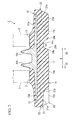
- the follower wheel is rotatably supported by the vehicle frame. Further, as shown in Fig. 2 , a plurality of trunk rollers 2 rotatably supported by the vehicle frame are disposed at a position between the driving wheel and follower wheel at the inner circumferential 11a side of the track main body 11.
- the trunk rollers 2 are rolled on the trunk roller surface S formed at the inner circumferential 11a side of the track main body 11 according to forwarding movement of the rubber track 10 in the track circumferential direction A.
- the trunk roller surface S continuously extends throughout the entire circumference of the track circumferential direction A in a portion of the inner circumferential 11a side of the track main body 11 disposed outside the track main body 11 in the track widthwise direction B situated outward of the protrusion section 13b of the core metal 12.
- the rubber track 10 is wound between the driving wheel and the follower wheel.
- an area of a portion of the ground surface 26 disposed at the one side B1 from the imaginary line L is larger than an area of a portion disposed at the other side B2. Accordingly, as described above, in a state in which the one side B1 is directed toward the inside of the track-type vehicle, the rubber track 10 is attached to the driving wheel. As a result, in the rubber track 10, the ground surface 26 of a portion disposed at a position of the inside of the track-type vehicle from the imaginary line L can be increased in comparison with the ground surface 26 disposed at the outside. In addition, durability of the portion disposed at the inside can be increased to hardly cause damage to the portion, and a lifespan of the rubber track 10 can be increased.
- a bump amount of the interval bump section 23 is set to be smaller than that of the first bump section 21 and the second bump section 22. Accordingly, the end section of the core metal 12 can be prevented from being cracked. As a result, the lifespan of the rubber track 10 can be increased.
- the through-groove sections 24 and 25 are asymmetrically disposed in the track widthwise direction B with respect to the imaginary line L. Accordingly, for example, like the embodiment, even when the plurality of lug sections 14 and 15 are substantially symmetrically disposed in the track widthwise direction B with respect to the imaginary line L, the areas of the ground surfaces 26 can be easily varied at both sides in the track widthwise direction B with respect to the imaginary line L. As a result, the above-mentioned effect can be reliably obtained.
- the first bump section 21 and the second bump section 22 have the concave surface 21b and the concave surface 22b, respectively.
- the bump amount of the first bump section 21 is gradually reduced from the other side B2 to the one side B1.
- the bump amount of the second bump section 22 is gradually reduced from the one side B1 to the other side B2. Accordingly, even when mud is stuck to the first bump section 21 and the second bump section 22 upon running of the track-type vehicle, the mud can be easily removed.
- the through-groove sections 24 and 25 are formed at the lug sections 14 and 15.
- a width in the track widthwise direction B of the first through-groove section 24 is gradually increased from the bottom surface 24a side toward the opening section 24b. Accordingly, even when the mud is stuck to the inside of the first through-groove section 24 upon running of the track-type vehicle, the mud can be easily removed from the first through-groove section 24. As a result, excavation of the rubber track 10 can be further improved, and the propulsive force of the rubber track 10 can be easily secured.
- the through-groove sections 24 and 25 are formed in the lug sections 14 and 15. Accordingly, a sideslip upon running of the track-type vehicle can be suppressed by an edge effect due to the edge sections 24c and 25c defining the opening sections 24b and 25b of the through-groove sections 24 and 25 of the lug sections 14 and 15.
- the technical scope of the present invention is not limited to the embodiment but various modifications may be made without departing from the teaching of the present invention.
- the first lug section 14 and the second lug section 15 may have the same shape and the same size.
- the plurality of lug sections 14 and 15 may be completely symmetrically disposed in the track widthwise direction B with respect to the imaginary line L.
- the first lug section 14 and the second lug section 15 may extend in the track widthwise direction B.
- the first bump section 21, the second bump section 22 and the interval bump section 23 may not be provided.
- a depth of the first through-groove section 24 may be set such that the bottom surface 24a of the first through-groove section 24 reaches the outer circumferential surface 11b of the track main body 11.
- the bottom surface 24a of the first through-groove section 24 is constituted by the track main body 11.
- the through-groove sections 24 and 25 are not limited to the configuration shown in the embodiment.
- the through-groove sections 24 and 25 may not be formed in all of the lugs.
- the second through-groove section 25 may not be formed in the second lug section 15.
- both of the first through-groove section 24 and the second through-groove section 25 may be formed in both of the lug sections 14 and 15.
- the second through-groove sections 25 are symmetrically disposed in the track widthwise direction B with respect to the imaginary line L, it is not limited thereto.
- the second through-groove sections 25 may be disposed on the imaginary line L while being deviated to the other side B2 with respect to the imaginary line L.
- the plurality of through-groove sections 24 and 25 may be asymmetrically disposed in the track widthwise direction B with respect to the imaginary line L.
- the plurality of through-groove sections can be symmetrically disposed in the track widthwise direction B with respect to the imaginary line L.
- first lug section 14 and the second lug section 15 deviated in the track widthwise direction B with respect to the imaginary line L are provided as the lug sections 14 and 15, it is not limited thereto.
- third lug sections 51 symmetrically disposed in the track widthwise direction B with respect to the imaginary line L may be provided as the lug section.
- the first through-groove sections 24 may be formed in every other third lug section 51, and for example, like the rubber track 60 shown in Fig. 6 , the first through-groove sections 24 may be formed in all of the third lug sections 51.
- the third lug section 51 extends throughout the entire length in the track widthwise direction B of the track main body 11, it is not limited thereto but the third lug section 51 may not extend throughout the entire length.
- top surfaces 14a and 15a of the lug sections 14 and 15 extend in the track widthwise direction B, it is not limited thereto.
- the top surfaces 14a and 15a of the lug sections 14 and 15 may be inclined with respect to the track widthwise direction B.
- the imaginary line L passes through a center in the track widthwise direction B of the track main body 11, it is not limited thereto.
- the imaginary line L may be deviated from the center in the track widthwise direction B.
- the driving wheel has a sprocket shape and the engaging hole 17 is formed in the lug interval section 16 of the track main body 11 as the engaging section engaged with the driving wheel
- the engaging hole 17 is formed in the lug interval section 16 of the track main body 11 as the engaging section engaged with the driving wheel
- engaging protrusion sections may protrude from the inner circumferential 11a side of the lug interval section 16 as the engaging section.
- the lifespan of the rubber track can be increased.
Landscapes
- Engineering & Computer Science (AREA)
- Chemical & Material Sciences (AREA)
- Combustion & Propulsion (AREA)
- Transportation (AREA)
- Mechanical Engineering (AREA)
- Tires In General (AREA)
- Handcart (AREA)
Applications Claiming Priority (2)
| Application Number | Priority Date | Filing Date | Title |
|---|---|---|---|
| JP2010262579 | 2010-11-25 | ||
| PCT/JP2011/077024 WO2012070609A1 (ja) | 2010-11-25 | 2011-11-24 | ゴムクローラ |
Publications (3)
| Publication Number | Publication Date |
|---|---|
| EP2644480A1 true EP2644480A1 (de) | 2013-10-02 |
| EP2644480A4 EP2644480A4 (de) | 2014-05-07 |
| EP2644480B1 EP2644480B1 (de) | 2018-02-21 |
Family
ID=46145947
Family Applications (1)
| Application Number | Title | Priority Date | Filing Date |
|---|---|---|---|
| EP11843624.5A Not-in-force EP2644480B1 (de) | 2010-11-25 | 2011-11-24 | Gummiraupenkette |
Country Status (6)
| Country | Link |
|---|---|
| US (1) | US9334000B2 (de) |
| EP (1) | EP2644480B1 (de) |
| JP (2) | JP5785952B2 (de) |
| CN (1) | CN103347775B (de) |
| CA (1) | CA2818841C (de) |
| WO (1) | WO2012070609A1 (de) |
Families Citing this family (9)
| Publication number | Priority date | Publication date | Assignee | Title |
|---|---|---|---|---|
| JP5851546B2 (ja) * | 2014-04-14 | 2016-02-03 | 株式会社ブリヂストン | クローラ |
| JP6499010B2 (ja) * | 2015-05-21 | 2019-04-10 | 株式会社ブリヂストン | 弾性クローラおよび弾性クローラ装置 |
| KR101788659B1 (ko) * | 2015-07-16 | 2017-11-15 | 동일고무벨트주식회사 | 러버트랙 |
| CN109715480B (zh) * | 2016-09-14 | 2021-08-31 | 福山橡胶工业株式会社 | 弹性履带牵引器和履带牵引式行驶装置 |
| US11572115B2 (en) * | 2019-07-17 | 2023-02-07 | Srj, Inc. | Tread pattern |
| US11970225B2 (en) | 2019-10-02 | 2024-04-30 | Polaris Industries Inc. | Snow track for a snowmobile |
| JP7404048B2 (ja) * | 2019-12-05 | 2023-12-25 | 株式会社ブリヂストン | クローラ走行装置、クロ-ラ監視システム、クロ-ラ走行車及びクロ-ラ監視方法 |
| CA3180766A1 (en) * | 2021-11-02 | 2023-05-02 | Soucy International Inc. | Endless track for track system and track system comprising same |
| JP2024031542A (ja) * | 2022-08-26 | 2024-03-07 | 住友ゴム工業株式会社 | 弾性クローラ |
Family Cites Families (17)
| Publication number | Priority date | Publication date | Assignee | Title |
|---|---|---|---|---|
| JPS58124379U (ja) | 1982-02-18 | 1983-08-24 | オ−ツタイヤ株式会社 | クロ−ラ用無端帯 |
| US5380076A (en) * | 1990-02-14 | 1995-01-10 | Kabushiki Kaisha Komatsu Seisakusho | Rubber crawler belt of a tracked vehicle |
| JPH06293281A (ja) * | 1993-04-06 | 1994-10-21 | Ohtsu Tire & Rubber Co Ltd :The | クローラ形走行装置 |
| EP0919455B1 (de) * | 1996-08-20 | 2007-03-07 | Yanmar Co., Ltd. | Schwenkbare erdbaumschine |
| JP3923602B2 (ja) * | 1997-07-01 | 2007-06-06 | ヤンマー株式会社 | 旋回作業車 |
| JPH10100955A (ja) | 1996-09-27 | 1998-04-21 | Komatsu Ltd | ゴム履帯のラグパターン |
| JP4188494B2 (ja) | 1999-04-28 | 2008-11-26 | 住友ゴム工業株式会社 | ゴムクローラ及びゴムクローラ走行装置 |
| JP2001322574A (ja) * | 2000-03-06 | 2001-11-20 | Bridgestone Corp | ゴムクローラ |
| JP2002002564A (ja) * | 2000-06-28 | 2002-01-09 | Komatsu Ltd | 履帯走行装置 |
| CA2337466C (en) * | 2001-02-22 | 2004-01-27 | Soucy International Inc. | Track with a drive pitch different from the tread pitch |
| JP4162513B2 (ja) | 2003-03-10 | 2008-10-08 | 株式会社クボタ | ゴムクローラ |
| JP4595345B2 (ja) | 2004-02-23 | 2010-12-08 | トヨタ自動車株式会社 | 半導体装置の製造方法 |
| JP3883129B2 (ja) | 2004-03-22 | 2007-02-21 | 住友ゴム工業株式会社 | 梯子型クローラ |
| JP4530405B2 (ja) * | 2004-05-27 | 2010-08-25 | 住友ゴム工業株式会社 | ゴムクローラ |
| KR100589650B1 (ko) * | 2004-10-29 | 2006-06-19 | 대륙화학공업 주식회사 | 탈륜방지용 무심금 크로라 |
| US20100013298A1 (en) * | 2006-08-25 | 2010-01-21 | Bridgestone Corporation | Rubber track |
| WO2010122929A1 (ja) * | 2009-04-22 | 2010-10-28 | 株式会社ブリヂストン | ゴムクローラ |
-
2011
- 2011-11-24 EP EP11843624.5A patent/EP2644480B1/de not_active Not-in-force
- 2011-11-24 JP JP2012545782A patent/JP5785952B2/ja not_active Expired - Fee Related
- 2011-11-24 CA CA2818841A patent/CA2818841C/en not_active Expired - Fee Related
- 2011-11-24 CN CN201180065882.4A patent/CN103347775B/zh not_active Expired - Fee Related
- 2011-11-24 WO PCT/JP2011/077024 patent/WO2012070609A1/ja not_active Ceased
- 2011-11-24 US US13/989,008 patent/US9334000B2/en active Active
-
2015
- 2015-03-30 JP JP2015070171A patent/JP5933783B2/ja not_active Expired - Fee Related
Also Published As
| Publication number | Publication date |
|---|---|
| US9334000B2 (en) | 2016-05-10 |
| JP2015143102A (ja) | 2015-08-06 |
| JP5785952B2 (ja) | 2015-09-30 |
| US20130241278A1 (en) | 2013-09-19 |
| JP5933783B2 (ja) | 2016-06-15 |
| CA2818841A1 (en) | 2012-05-31 |
| WO2012070609A1 (ja) | 2012-05-31 |
| CN103347775B (zh) | 2016-01-20 |
| EP2644480B1 (de) | 2018-02-21 |
| JPWO2012070609A1 (ja) | 2014-05-19 |
| CN103347775A (zh) | 2013-10-09 |
| EP2644480A4 (de) | 2014-05-07 |
| CA2818841C (en) | 2017-03-07 |
Similar Documents
| Publication | Publication Date | Title |
|---|---|---|
| US9334000B2 (en) | Rubber track | |
| CN102481957B (zh) | 履带式行进装置 | |
| CA2994092A1 (en) | Elastic crawler and elastic crawler device | |
| EP3356211B1 (de) | Selbstausrichtender leitradentwurf für gummiraupenkette | |
| JP4142932B2 (ja) | 弾性クローラ | |
| US9919752B2 (en) | Elastic crawler | |
| PH12015000272A1 (en) | Duo crawler for wet paddy with improved in mud extraction performance | |
| JP2009029206A (ja) | ゴムクローラ | |
| JP6779583B2 (ja) | 弾性クローラ | |
| JP2009255863A (ja) | ゴムクローラ | |
| US10435090B2 (en) | Elastic crawler | |
| JP5657258B2 (ja) | ゴムクローラ及びゴムクローラ組込体 | |
| JP4376333B2 (ja) | 低振動ゴムクローラ | |
| JP5587656B2 (ja) | クローラ式走行装置 | |
| JP5871488B2 (ja) | ゴムクローラ | |
| JP6479319B2 (ja) | ゴムクローラ | |
| JPH08150969A (ja) | 弾性クローラ | |
| JP4878927B2 (ja) | ゴムクローラ | |
| JPS6236695Y2 (de) | ||
| JP2000159161A (ja) | ゴムクローラ | |
| JPS607273Y2 (ja) | クロ−ラ走行式農作業機 | |
| JP2009227033A (ja) | 芯金レスゴムクローラ | |
| JP2022032336A (ja) | 弾性クローラ | |
| JP2012006471A (ja) | クローラ式走行装置 | |
| JP2014189085A (ja) | ゴムクローラ |
Legal Events
| Date | Code | Title | Description |
|---|---|---|---|
| PUAI | Public reference made under article 153(3) epc to a published international application that has entered the european phase |
Free format text: ORIGINAL CODE: 0009012 |
|
| 17P | Request for examination filed |
Effective date: 20130524 |
|
| AK | Designated contracting states |
Kind code of ref document: A1 Designated state(s): AL AT BE BG CH CY CZ DE DK EE ES FI FR GB GR HR HU IE IS IT LI LT LU LV MC MK MT NL NO PL PT RO RS SE SI SK SM TR |
|
| DAX | Request for extension of the european patent (deleted) | ||
| REG | Reference to a national code |
Ref country code: DE Ref legal event code: R079 Ref document number: 602011045895 Country of ref document: DE Free format text: PREVIOUS MAIN CLASS: B62D0055253000 Ipc: B62D0055240000 |
|
| A4 | Supplementary search report drawn up and despatched |
Effective date: 20140407 |
|
| RIC1 | Information provided on ipc code assigned before grant |
Ipc: B62D 55/26 20060101ALI20140401BHEP Ipc: B62D 55/24 20060101AFI20140401BHEP |
|
| 17Q | First examination report despatched |
Effective date: 20161024 |
|
| GRAP | Despatch of communication of intention to grant a patent |
Free format text: ORIGINAL CODE: EPIDOSNIGR1 |
|
| INTG | Intention to grant announced |
Effective date: 20170831 |
|
| GRAS | Grant fee paid |
Free format text: ORIGINAL CODE: EPIDOSNIGR3 |
|
| GRAA | (expected) grant |
Free format text: ORIGINAL CODE: 0009210 |
|
| AK | Designated contracting states |
Kind code of ref document: B1 Designated state(s): AL AT BE BG CH CY CZ DE DK EE ES FI FR GB GR HR HU IE IS IT LI LT LU LV MC MK MT NL NO PL PT RO RS SE SI SK SM TR |
|
| REG | Reference to a national code |
Ref country code: GB Ref legal event code: FG4D |
|
| REG | Reference to a national code |
Ref country code: CH Ref legal event code: EP |
|
| REG | Reference to a national code |
Ref country code: AT Ref legal event code: REF Ref document number: 971398 Country of ref document: AT Kind code of ref document: T Effective date: 20180315 |
|
| REG | Reference to a national code |
Ref country code: IE Ref legal event code: FG4D |
|
| REG | Reference to a national code |
Ref country code: DE Ref legal event code: R096 Ref document number: 602011045895 Country of ref document: DE |
|
| REG | Reference to a national code |
Ref country code: NL Ref legal event code: MP Effective date: 20180221 |
|
| REG | Reference to a national code |
Ref country code: LT Ref legal event code: MG4D |
|
| REG | Reference to a national code |
Ref country code: AT Ref legal event code: MK05 Ref document number: 971398 Country of ref document: AT Kind code of ref document: T Effective date: 20180221 |
|
| PG25 | Lapsed in a contracting state [announced via postgrant information from national office to epo] |
Ref country code: FI Free format text: LAPSE BECAUSE OF FAILURE TO SUBMIT A TRANSLATION OF THE DESCRIPTION OR TO PAY THE FEE WITHIN THE PRESCRIBED TIME-LIMIT Effective date: 20180221 Ref country code: NO Free format text: LAPSE BECAUSE OF FAILURE TO SUBMIT A TRANSLATION OF THE DESCRIPTION OR TO PAY THE FEE WITHIN THE PRESCRIBED TIME-LIMIT Effective date: 20180521 Ref country code: CY Free format text: LAPSE BECAUSE OF FAILURE TO SUBMIT A TRANSLATION OF THE DESCRIPTION OR TO PAY THE FEE WITHIN THE PRESCRIBED TIME-LIMIT Effective date: 20180221 Ref country code: HR Free format text: LAPSE BECAUSE OF FAILURE TO SUBMIT A TRANSLATION OF THE DESCRIPTION OR TO PAY THE FEE WITHIN THE PRESCRIBED TIME-LIMIT Effective date: 20180221 Ref country code: NL Free format text: LAPSE BECAUSE OF FAILURE TO SUBMIT A TRANSLATION OF THE DESCRIPTION OR TO PAY THE FEE WITHIN THE PRESCRIBED TIME-LIMIT Effective date: 20180221 Ref country code: LT Free format text: LAPSE BECAUSE OF FAILURE TO SUBMIT A TRANSLATION OF THE DESCRIPTION OR TO PAY THE FEE WITHIN THE PRESCRIBED TIME-LIMIT Effective date: 20180221 Ref country code: ES Free format text: LAPSE BECAUSE OF FAILURE TO SUBMIT A TRANSLATION OF THE DESCRIPTION OR TO PAY THE FEE WITHIN THE PRESCRIBED TIME-LIMIT Effective date: 20180221 |
|
| PG25 | Lapsed in a contracting state [announced via postgrant information from national office to epo] |
Ref country code: LV Free format text: LAPSE BECAUSE OF FAILURE TO SUBMIT A TRANSLATION OF THE DESCRIPTION OR TO PAY THE FEE WITHIN THE PRESCRIBED TIME-LIMIT Effective date: 20180221 Ref country code: BG Free format text: LAPSE BECAUSE OF FAILURE TO SUBMIT A TRANSLATION OF THE DESCRIPTION OR TO PAY THE FEE WITHIN THE PRESCRIBED TIME-LIMIT Effective date: 20180521 Ref country code: SE Free format text: LAPSE BECAUSE OF FAILURE TO SUBMIT A TRANSLATION OF THE DESCRIPTION OR TO PAY THE FEE WITHIN THE PRESCRIBED TIME-LIMIT Effective date: 20180221 Ref country code: RS Free format text: LAPSE BECAUSE OF FAILURE TO SUBMIT A TRANSLATION OF THE DESCRIPTION OR TO PAY THE FEE WITHIN THE PRESCRIBED TIME-LIMIT Effective date: 20180221 Ref country code: AT Free format text: LAPSE BECAUSE OF FAILURE TO SUBMIT A TRANSLATION OF THE DESCRIPTION OR TO PAY THE FEE WITHIN THE PRESCRIBED TIME-LIMIT Effective date: 20180221 Ref country code: GR Free format text: LAPSE BECAUSE OF FAILURE TO SUBMIT A TRANSLATION OF THE DESCRIPTION OR TO PAY THE FEE WITHIN THE PRESCRIBED TIME-LIMIT Effective date: 20180522 |
|
| PG25 | Lapsed in a contracting state [announced via postgrant information from national office to epo] |
Ref country code: RO Free format text: LAPSE BECAUSE OF FAILURE TO SUBMIT A TRANSLATION OF THE DESCRIPTION OR TO PAY THE FEE WITHIN THE PRESCRIBED TIME-LIMIT Effective date: 20180221 Ref country code: EE Free format text: LAPSE BECAUSE OF FAILURE TO SUBMIT A TRANSLATION OF THE DESCRIPTION OR TO PAY THE FEE WITHIN THE PRESCRIBED TIME-LIMIT Effective date: 20180221 Ref country code: PL Free format text: LAPSE BECAUSE OF FAILURE TO SUBMIT A TRANSLATION OF THE DESCRIPTION OR TO PAY THE FEE WITHIN THE PRESCRIBED TIME-LIMIT Effective date: 20180221 Ref country code: AL Free format text: LAPSE BECAUSE OF FAILURE TO SUBMIT A TRANSLATION OF THE DESCRIPTION OR TO PAY THE FEE WITHIN THE PRESCRIBED TIME-LIMIT Effective date: 20180221 |
|
| REG | Reference to a national code |
Ref country code: DE Ref legal event code: R097 Ref document number: 602011045895 Country of ref document: DE |
|
| PG25 | Lapsed in a contracting state [announced via postgrant information from national office to epo] |
Ref country code: DK Free format text: LAPSE BECAUSE OF FAILURE TO SUBMIT A TRANSLATION OF THE DESCRIPTION OR TO PAY THE FEE WITHIN THE PRESCRIBED TIME-LIMIT Effective date: 20180221 Ref country code: SK Free format text: LAPSE BECAUSE OF FAILURE TO SUBMIT A TRANSLATION OF THE DESCRIPTION OR TO PAY THE FEE WITHIN THE PRESCRIBED TIME-LIMIT Effective date: 20180221 Ref country code: CZ Free format text: LAPSE BECAUSE OF FAILURE TO SUBMIT A TRANSLATION OF THE DESCRIPTION OR TO PAY THE FEE WITHIN THE PRESCRIBED TIME-LIMIT Effective date: 20180221 Ref country code: SM Free format text: LAPSE BECAUSE OF FAILURE TO SUBMIT A TRANSLATION OF THE DESCRIPTION OR TO PAY THE FEE WITHIN THE PRESCRIBED TIME-LIMIT Effective date: 20180221 |
|
| PLBE | No opposition filed within time limit |
Free format text: ORIGINAL CODE: 0009261 |
|
| STAA | Information on the status of an ep patent application or granted ep patent |
Free format text: STATUS: NO OPPOSITION FILED WITHIN TIME LIMIT |
|
| 26N | No opposition filed |
Effective date: 20181122 |
|
| PG25 | Lapsed in a contracting state [announced via postgrant information from national office to epo] |
Ref country code: SI Free format text: LAPSE BECAUSE OF FAILURE TO SUBMIT A TRANSLATION OF THE DESCRIPTION OR TO PAY THE FEE WITHIN THE PRESCRIBED TIME-LIMIT Effective date: 20180221 |
|
| REG | Reference to a national code |
Ref country code: CH Ref legal event code: PL |
|
| PG25 | Lapsed in a contracting state [announced via postgrant information from national office to epo] |
Ref country code: LU Free format text: LAPSE BECAUSE OF NON-PAYMENT OF DUE FEES Effective date: 20181124 Ref country code: MC Free format text: LAPSE BECAUSE OF FAILURE TO SUBMIT A TRANSLATION OF THE DESCRIPTION OR TO PAY THE FEE WITHIN THE PRESCRIBED TIME-LIMIT Effective date: 20180221 |
|
| REG | Reference to a national code |
Ref country code: BE Ref legal event code: MM Effective date: 20181130 |
|
| REG | Reference to a national code |
Ref country code: IE Ref legal event code: MM4A |
|
| PG25 | Lapsed in a contracting state [announced via postgrant information from national office to epo] |
Ref country code: CH Free format text: LAPSE BECAUSE OF NON-PAYMENT OF DUE FEES Effective date: 20181130 Ref country code: LI Free format text: LAPSE BECAUSE OF NON-PAYMENT OF DUE FEES Effective date: 20181130 |
|
| PG25 | Lapsed in a contracting state [announced via postgrant information from national office to epo] |
Ref country code: IE Free format text: LAPSE BECAUSE OF NON-PAYMENT OF DUE FEES Effective date: 20181124 |
|
| PG25 | Lapsed in a contracting state [announced via postgrant information from national office to epo] |
Ref country code: BE Free format text: LAPSE BECAUSE OF NON-PAYMENT OF DUE FEES Effective date: 20181130 |
|
| PG25 | Lapsed in a contracting state [announced via postgrant information from national office to epo] |
Ref country code: MT Free format text: LAPSE BECAUSE OF NON-PAYMENT OF DUE FEES Effective date: 20181124 |
|
| PGFP | Annual fee paid to national office [announced via postgrant information from national office to epo] |
Ref country code: IT Payment date: 20191128 Year of fee payment: 9 |
|
| PG25 | Lapsed in a contracting state [announced via postgrant information from national office to epo] |
Ref country code: TR Free format text: LAPSE BECAUSE OF FAILURE TO SUBMIT A TRANSLATION OF THE DESCRIPTION OR TO PAY THE FEE WITHIN THE PRESCRIBED TIME-LIMIT Effective date: 20180221 |
|
| PGFP | Annual fee paid to national office [announced via postgrant information from national office to epo] |
Ref country code: GB Payment date: 20191120 Year of fee payment: 9 |
|
| PG25 | Lapsed in a contracting state [announced via postgrant information from national office to epo] |
Ref country code: PT Free format text: LAPSE BECAUSE OF FAILURE TO SUBMIT A TRANSLATION OF THE DESCRIPTION OR TO PAY THE FEE WITHIN THE PRESCRIBED TIME-LIMIT Effective date: 20180221 |
|
| PG25 | Lapsed in a contracting state [announced via postgrant information from national office to epo] |
Ref country code: MK Free format text: LAPSE BECAUSE OF NON-PAYMENT OF DUE FEES Effective date: 20180221 Ref country code: HU Free format text: LAPSE BECAUSE OF FAILURE TO SUBMIT A TRANSLATION OF THE DESCRIPTION OR TO PAY THE FEE WITHIN THE PRESCRIBED TIME-LIMIT; INVALID AB INITIO Effective date: 20111124 |
|
| PG25 | Lapsed in a contracting state [announced via postgrant information from national office to epo] |
Ref country code: IS Free format text: LAPSE BECAUSE OF FAILURE TO SUBMIT A TRANSLATION OF THE DESCRIPTION OR TO PAY THE FEE WITHIN THE PRESCRIBED TIME-LIMIT Effective date: 20180621 |
|
| PGFP | Annual fee paid to national office [announced via postgrant information from national office to epo] |
Ref country code: DE Payment date: 20201119 Year of fee payment: 10 Ref country code: FR Payment date: 20201120 Year of fee payment: 10 |
|
| GBPC | Gb: european patent ceased through non-payment of renewal fee |
Effective date: 20201124 |
|
| PG25 | Lapsed in a contracting state [announced via postgrant information from national office to epo] |
Ref country code: IT Free format text: LAPSE BECAUSE OF NON-PAYMENT OF DUE FEES Effective date: 20201124 |
|
| PG25 | Lapsed in a contracting state [announced via postgrant information from national office to epo] |
Ref country code: GB Free format text: LAPSE BECAUSE OF NON-PAYMENT OF DUE FEES Effective date: 20201124 |
|
| REG | Reference to a national code |
Ref country code: DE Ref legal event code: R119 Ref document number: 602011045895 Country of ref document: DE |
|
| PG25 | Lapsed in a contracting state [announced via postgrant information from national office to epo] |
Ref country code: DE Free format text: LAPSE BECAUSE OF NON-PAYMENT OF DUE FEES Effective date: 20220601 |
|
| PG25 | Lapsed in a contracting state [announced via postgrant information from national office to epo] |
Ref country code: FR Free format text: LAPSE BECAUSE OF NON-PAYMENT OF DUE FEES Effective date: 20211130 |