EP2644836A2 - Segment d'enveloppe refroidi par effusion avec un revêtement abradable - Google Patents
Segment d'enveloppe refroidi par effusion avec un revêtement abradable Download PDFInfo
- Publication number
- EP2644836A2 EP2644836A2 EP13158528.3A EP13158528A EP2644836A2 EP 2644836 A2 EP2644836 A2 EP 2644836A2 EP 13158528 A EP13158528 A EP 13158528A EP 2644836 A2 EP2644836 A2 EP 2644836A2
- Authority
- EP
- European Patent Office
- Prior art keywords
- grooves
- seal segment
- abradable coating
- turbine
- coolant
- Prior art date
- Legal status (The legal status is an assumption and is not a legal conclusion. Google has not performed a legal analysis and makes no representation as to the accuracy of the status listed.)
- Granted
Links
Images



Classifications
-
- F—MECHANICAL ENGINEERING; LIGHTING; HEATING; WEAPONS; BLASTING
- F02—COMBUSTION ENGINES; HOT-GAS OR COMBUSTION-PRODUCT ENGINE PLANTS
- F02C—GAS-TURBINE PLANTS; AIR INTAKES FOR JET-PROPULSION PLANTS; CONTROLLING FUEL SUPPLY IN AIR-BREATHING JET-PROPULSION PLANTS
- F02C7/00—Features, components parts, details or accessories, not provided for in, or of interest apart form groups F02C1/00 - F02C6/00; Air intakes for jet-propulsion plants
- F02C7/12—Cooling of plants
-
- F—MECHANICAL ENGINEERING; LIGHTING; HEATING; WEAPONS; BLASTING
- F01—MACHINES OR ENGINES IN GENERAL; ENGINE PLANTS IN GENERAL; STEAM ENGINES
- F01D—NON-POSITIVE DISPLACEMENT MACHINES OR ENGINES, e.g. STEAM TURBINES
- F01D11/00—Preventing or minimising internal leakage of working-fluid, e.g. between stages
- F01D11/08—Preventing or minimising internal leakage of working-fluid, e.g. between stages for sealing space between rotor blade tips and stator
- F01D11/12—Preventing or minimising internal leakage of working-fluid, e.g. between stages for sealing space between rotor blade tips and stator using a rubstrip, e.g. erodible. deformable or resiliently-biased part
- F01D11/122—Preventing or minimising internal leakage of working-fluid, e.g. between stages for sealing space between rotor blade tips and stator using a rubstrip, e.g. erodible. deformable or resiliently-biased part with erodable or abradable material
-
- F—MECHANICAL ENGINEERING; LIGHTING; HEATING; WEAPONS; BLASTING
- F05—INDEXING SCHEMES RELATING TO ENGINES OR PUMPS IN VARIOUS SUBCLASSES OF CLASSES F01-F04
- F05D—INDEXING SCHEME FOR ASPECTS RELATING TO NON-POSITIVE-DISPLACEMENT MACHINES OR ENGINES, GAS-TURBINES OR JET-PROPULSION PLANTS
- F05D2230/00—Manufacture
- F05D2230/90—Coating; Surface treatment
-
- F—MECHANICAL ENGINEERING; LIGHTING; HEATING; WEAPONS; BLASTING
- F05—INDEXING SCHEMES RELATING TO ENGINES OR PUMPS IN VARIOUS SUBCLASSES OF CLASSES F01-F04
- F05D—INDEXING SCHEME FOR ASPECTS RELATING TO NON-POSITIVE-DISPLACEMENT MACHINES OR ENGINES, GAS-TURBINES OR JET-PROPULSION PLANTS
- F05D2240/00—Components
- F05D2240/10—Stators
- F05D2240/11—Shroud seal segments
-
- F—MECHANICAL ENGINEERING; LIGHTING; HEATING; WEAPONS; BLASTING
- F05—INDEXING SCHEMES RELATING TO ENGINES OR PUMPS IN VARIOUS SUBCLASSES OF CLASSES F01-F04
- F05D—INDEXING SCHEME FOR ASPECTS RELATING TO NON-POSITIVE-DISPLACEMENT MACHINES OR ENGINES, GAS-TURBINES OR JET-PROPULSION PLANTS
- F05D2300/00—Materials; Properties thereof
- F05D2300/10—Metals, alloys or intermetallic compounds
- F05D2300/13—Refractory metals, i.e. Ti, V, Cr, Zr, Nb, Mo, Hf, Ta, W
- F05D2300/134—Zirconium
Definitions
- the present invention relates to effusion cooling of seal segments within a gas turbine engine.
- Modern gas turbine engines and more specifically turbofans for use in aviation, provide power by compressing air using a compressor, adding fuel to this compressed air, combusting this mixture such that it expands through the blades of a turbine and exhausting the produced gases.
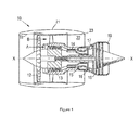
- a ducted fan gas turbine engine generally indicated at 10 has a principal and rotational axis X-X.
- the engine comprises, in axial flow series, an air intake 11, a propulsive fan 12, an intermediate pressure compressor 13, a high-pressure compressor 14, combustion equipment 15, a high-pressure turbine 16, and intermediate pressure turbine 17, a low-pressure turbine 18 and a core engine exhaust nozzle 19.
- a nacelle 21 generally surrounds the engine 10 and defines the intake 11, a bypass duct 22 and a bypass exhaust nozzle 23.
- the gas turbine engine 10 works in a conventional manner so that air entering the intake 11 is accelerated by the fan 12 to produce two air flows: a first air flow A into the intermediate pressure compressor 13 and a second air flow B which passes through the bypass duct 22 to provide propulsive thrust.
- the intermediate pressure compressor 13 compresses the air flow A directed into it before delivering that air to the high pressure compressor 14 where further compression takes place.
- the compressed air exhausted from the high-pressure compressor 14 is directed into the combustion equipment 15 where it is mixed with fuel and the mixture combusted.
- the resultant hot combustion products then expand through, and thereby drive the high, intermediate and low-pressure turbines 16, 17, 18 before being exhausted through the nozzle 19 to provide additional propulsive thrust.
- the high, intermediate and low-pressure turbines respectively drive the high and intermediate pressure compressors 14, 13 and the fan 12 by suitable interconnecting shafts.
- the high-pressure turbine gas temperatures are hotter than the melting point of the material of the blades and vanes, necessitating internal air cooling of these airfoil components.
- the mean temperature of the gas stream decreases as power is extracted. Therefore, the need to cool the static and rotary parts of the engine structure decreases as the gas moves from the high-pressure stage(s), through the intermediate-pressure and low-pressure stages, and towards the exit nozzle.
- Figure 2 shows an isometric view of a typical single stage cooled turbine. Cooling air flows are indicated by arrows.
- High-pressure turbine nozzle guide vanes 31 consume the greatest amount of cooling air on high temperature engines.
- High-pressure blades 32 typically use about half of the NGV flow.
- the intermediate-pressure and low-pressure stages downstream of the HP turbine use progressively less cooling air.
- the high-pressure turbine airfoils are cooled by using high pressure air from the compressor that has by-passed the combustor and is therefore relatively cool compared to the gas temperature.
- Typical cooling air temperatures are between 800 and 1000 K, while gas temperatures can be in excess of 2100 K.
- the cooling air from the compressor that is used to cool the hot turbine components is not used fully to extract work from the turbine. Therefore, as extracting coolant flow has an adverse effect on the engine operating efficiency, it is important to use the cooling air effectively.
- the turbine In an unshrouded turbine, the turbine consists of a disc, rotating about the central shaft of the engine, and a plurality of blades extending radially out from the disc towards the engine casing of the engine. Expansion through the turbine causes its blades to rotate at high speed. The blades of the turbine rotate closely to, and within, an annular assembly of seal segments that form a seal segment ring around the tips of the turbine blades.
- the tip clearance As the turbine rotates, the distance between the tips of the blades and the seal segments is known as the tip clearance. It is desirable for the tips of the turbine blades to rotate as close to the seal segments without rubbing as possible because as the tip clearance increases, the efficiency of the turbine decreases, as a portion of the expanded gas flow will pass through the tip clearance. This is known as over-tip leakage.
- Steps have been taken in order to minimise the over tip leakage.
- Some engines are fitted with an abradable coating on the inside of the seal segment, against which the blades can rub. This means that the blades will cut a groove in this lining, to form a seal against the casing.
- the seal segment is cooled by impingement. Coolant is contained within an annular duct formed by the inner wall of the engine casing and the outer surface of the ring seal segments, which impinges the coolant onto the back face of the seal segment inner wall.
- This method requires a large flow of coolant to sufficiently cool the abradable layer and keep it at an acceptable temperature due to the thermal resistance of the seal segment wall between the coolant and the radially inner surface of the abradable material.
- Coolant is discharged from an outboard annular duct through one or more very small diameter radial ducts, which extend through the seal segment and abradable coating.
- the coolant can therefore cool the seal segment and abradable coating, being in direct contact with both of these components, and finally be impinged on the turbine blade tips.
- GB2009329A describes a turbine wheel shroud of porous abradable material, incorporating transverse, non-porous, divisions to prevent axial flow losses of the cooling air along the length of the shroud.
- a general aim of aspects of the invention is to provide a means for effusion cooling a seal segment incorporating an abrasive coating.
- Another general aim of aspects of the invention is to provide a means of stopping abraded material blocking the effusion ducts.
- the invention provides a turbine casing assembly, comprising an annular seal segment assembly for surrounding the turbine adjacent to the turbine blades; an abradable coating on the inboard surface of the seal segments of the seal segment assembly; one or more coolant ducts extending from the outboard surface of a respective seal segment through the seal segment and abradable coating for carrying a coolant towards the blade tips; and, one or more annular grooves formed in the inboard surface of the abradable coating, the or each coolant duct opening into one of the one or more annular grooves.
- the coolant ducts may extend in a substantially radial direction, or at an angle to the radial direction.
- the annular grooves may extend circumferentially or at an angle to the circumference around the inboard surface of the abradable coating.
- the grooves may be of any suitable cross section, although preferably the mouth of each groove opening towards the blades is no narrower than the inner end of the groove (furthest from the blade).
- Suitable cross sections include a rectangular or trapezoidal cross section.
- the grooves extend continuously from one edge of the seal segment to another edge of the seal segment.
- some or all of the grooves may terminate in end walls within the perimeter of the seal segment. In this way air entrained in a groove can be forced inwards, by an end wall of the groove, towards the blade tips.
- the end walls of the grooves may be radiused to have a concave shape to encourage this flow of air.
- a bond layer material may be present between the abradable coating and the inboard surface of the seal segment.
- this bond layer is formed from a material with a thermal expansion coefficient value that falls between the thermal coefficient values of the seal segment and abradable lining respectively.
- this bond layer comprises zirconia.
- the invention provides a method for the effusive cooling of a seal segment assembly of a turbine, within a turbine casing, comprising passing a coolant through one or more ducts, from the outboard edge of the seal segment assembly, towards the turbine blades, each of the one or more ducts passing through a seal segment of the seal segment assembly and an abradable coating and opening towards the turbine, wherein one or more annular grooves are formed in the inboard surface of the abradable coating, the or each coolant duct opening into one of the one or more annular grooves; and, effusing the coolant from the duct towards the turbine; whereby, any abraded coating can pass into the grooves, so as not to obstruct the ducts.
- the invention provides a turbine assembly, comprising a turbine having a plurality of radially extending blades, an annular seal segment assembly surrounding the turbine adjacent to the tips of the turbine blades, the seal segment assembly comprising as plurality of seal segments; an abradable coating on the inboard surface of each seal segment; one or more coolant ducts extending from the outboard edge of the seal segment through the seal segment and abradable coating, for carrying a coolant towards the blade tips; and, one or more annular grooves formed in the inboard surface of the abradable coating, the or each coolant duct opening into one of the one or more annular grooves.
- the turbine blades may have abrasive tips, for example comprising abrasive grit embedded or similarly attached to the tip of the blade.
- the grooves in the abradable layer help to prevent material abraded from that layer blocking the effusion ducts. More specifically, the relatively large cross-section grooves (compared with the cross-section of the ducts) provide a space in which the abraded material can collect without blocking the ducts and from where it can subsequently be removed due to gas washing the seal segment surface.
- Figure 3 shows a side elevation of a seal segment 40 of a seal segment ring of a gas turbine in accordance with an embodiment of the present invention.
- a bond interlayer 42 bonds an abradable coating layer 44 to the radially inner surface of the seal segment 40.
- the seal segment ring surrounds the tips of turbine blades 46, which rotate within the seal segment 40 assembly.
- Coolant is effused 48 from the outboard side 50 of the seal segment 40 through a series of effusion ducts 52, which extend through the seal segment 40, bond interlayer 42 and abradable coating 44 towards the turbine blades 46.
- the effusion ducts 52 open into one or more grooves 54, which are provided in the inboard surface of the abradable coating 44.
- the grooves 54 are longitudinal and extend circumferentially around the seal segment so as to form annular grooves 54.
- the grooves 54 lie in a parallel orientation relative to one another and to the edge of the circumferential edge of the segment. The dimensions, spacing and cross-section of the grooves is determined by the cooling requirements and what is deemed necessary for preventing a build up of material in use.
- the thickness of abradable liner is between 3mm and 5mm.
- the groove 54 depth may be between 2mm and 3mm to allow for rubs from the blades. It will be appreciated that this will allow a rub up to approximately 2mm.
- the expected grit size may be between 0.1-0.2mm but may be larger or smaller depending on the application.
- the width of the grooves may be up to 1.5mm.
- the holes may be up to 1mm in diameter.
- the tips 56 of the turbine blades 46 incorporate an abrasive material 58. As the blades rotate, these abrasive tips 56 will cut a slight groove 60 into the inboard surface of the abradable coating layer 44 to form a minimal tip clearance between the abradable layer 44 and the blade tips 56.
- the bond interlayer 42 which may comprise zirconia, has a thermal expansion coefficient between that of the seal segment 40 and the abradable material 44. This means that as the seal segment 40, bond interlayer 42 and abradable layer 44 expand and contract, due to heating and cooling, the effects of 'thermal mismatch' will be ameliorated.
- the grooves 54 are of sufficiently large cross-section that they will not be blocked by abraded material 62 which flows into them before it is washed away.
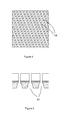
- the grooves 54 may be circumferential around the inboard surface of the abradable layer 44, or may be at an angle to the circumferential direction, as seen in fig. 4 .
- the grooves predominantly extend in a circumferential direction but extend laterally across the segments, in an axial direction relative to the principal direction of rotation of the blades, from one side of the segment to the other.
- the angle of incidence with the rotational path of the blades may be up to 50 degrees.
- the grooves 54 may be of rectangular cross section as seen in fig. 3 , or any other suitable cross section, for example of trapezoidal cross section, as shown in fig. 5 . That is, the grooves may diverge as they extend through the abradable liner towards the outboard surface.
- the initial touches by the blade tips 56 will remove less abradable material 44 than subsequent touches, which will produce less friction and subsequently, less excess heat.
- the grooves 54 are continuous from one edge of the seal segment 40 to another edge of the seal segment 40.
- Figs. 6 and 7 show an alternative embodiment in which the grooves 54' are discontinuous and stop short of the edges of the seal segment 40. More specifically, an array of grooves 54' are formed in the surface of the abradable layer 44 on the inboard surface of the seal segment 40. In this example the grooves 54' are arranged in a regular pattern, in rows of longitudinally aligned grooves 54', with the grooves 54' of one row being off-set longitudinally from the grooves of adjacent rows.
- One or more effusion ducts 52 open into each groove 54'.
- each groove 54' is radiused to provide a smooth, concave shape, to turn entrained air inwards towards the blade tips 56, as indicated by arrow 66.
- seal segments described above can be produced by coating the seal segment 40 with an abradable layer 44 and then machining the grooves 54 in-situ around the inboard surface of the abradable layer.
- the effusion ducts 52 can then be drilled through the abradable layer 44, within the grooves 54, and through the seal segment 40.
- the effusion ducts 52 can be drilled in the seal segment 40 prior to coating the inboard surface with the abradable layer.
- the holes can then be masked off on the inboard side of the seal segment and the abradable layer 44 applied.
- the masking can then be removed to reveal the holes on the inboard side of the seal segment 40, through the abradable layer 44.
- the grooves 54 can then be machined in-situ, such that the holes exit into said grooves.
Landscapes
- Engineering & Computer Science (AREA)
- Mechanical Engineering (AREA)
- General Engineering & Computer Science (AREA)
- Chemical & Material Sciences (AREA)
- Combustion & Propulsion (AREA)
- Turbine Rotor Nozzle Sealing (AREA)
Applications Claiming Priority (1)
| Application Number | Priority Date | Filing Date | Title |
|---|---|---|---|
| GBGB1205663.6A GB201205663D0 (en) | 2012-03-30 | 2012-03-30 | Effusion cooled shroud segment with an abradable system |
Publications (3)
| Publication Number | Publication Date |
|---|---|
| EP2644836A2 true EP2644836A2 (fr) | 2013-10-02 |
| EP2644836A3 EP2644836A3 (fr) | 2017-07-12 |
| EP2644836B1 EP2644836B1 (fr) | 2019-05-08 |
Family
ID=46160008
Family Applications (1)
| Application Number | Title | Priority Date | Filing Date |
|---|---|---|---|
| EP13158528.3A Active EP2644836B1 (fr) | 2012-03-30 | 2013-03-11 | Ensemble de turbine à gaz avec segment d'enveloppe refroidi par effusion avec un revêtement abradable |
Country Status (3)
| Country | Link |
|---|---|
| US (1) | US9528443B2 (fr) |
| EP (1) | EP2644836B1 (fr) |
| GB (1) | GB201205663D0 (fr) |
Cited By (5)
| Publication number | Priority date | Publication date | Assignee | Title |
|---|---|---|---|---|
| WO2015130535A1 (fr) * | 2014-02-25 | 2015-09-03 | Siemens Energy, Inc. | Couche abradable de turbine avec nervures étagées à zone d'usure progressive |
| EP3252274A1 (fr) * | 2016-06-01 | 2017-12-06 | United Technologies Corporation | Mesure d'dosage et direction de joint annulaire |
| US10189082B2 (en) | 2014-02-25 | 2019-01-29 | Siemens Aktiengesellschaft | Turbine shroud with abradable layer having dimpled forward zone |
| US10190435B2 (en) | 2015-02-18 | 2019-01-29 | Siemens Aktiengesellschaft | Turbine shroud with abradable layer having ridges with holes |
| US10408079B2 (en) | 2015-02-18 | 2019-09-10 | Siemens Aktiengesellschaft | Forming cooling passages in thermal barrier coated, combustion turbine superalloy components |
Families Citing this family (8)
| Publication number | Priority date | Publication date | Assignee | Title |
|---|---|---|---|---|
| JP2013177875A (ja) * | 2012-02-29 | 2013-09-09 | Ihi Corp | ガスタービンエンジン |
| US9957834B2 (en) * | 2013-10-03 | 2018-05-01 | United Technologies Corporation | Rotor blade tip clearance |
| US9718735B2 (en) * | 2015-02-03 | 2017-08-01 | General Electric Company | CMC turbine components and methods of forming CMC turbine components |
| US10487847B2 (en) | 2016-01-19 | 2019-11-26 | Pratt & Whitney Canada Corp. | Gas turbine engine blade casing |
| JP6725273B2 (ja) * | 2016-03-11 | 2020-07-15 | 三菱日立パワーシステムズ株式会社 | 翼、これを備えているガスタービン |
| US10495103B2 (en) * | 2016-12-08 | 2019-12-03 | United Technologies Corporation | Fan blade having a tip assembly |
| GB201700914D0 (en) * | 2017-01-19 | 2017-03-08 | Rolls Royce Plc | A sealing element and a method of maufacturing the same |
| FR3071247B1 (fr) * | 2017-09-21 | 2019-09-20 | Safran Ceramics | Procede de fabrication d'une piece en cmc |
Family Cites Families (18)
| Publication number | Priority date | Publication date | Assignee | Title |
|---|---|---|---|---|
| FR2401310A1 (fr) | 1977-08-26 | 1979-03-23 | Snecma | Carter de turbine de moteur a reaction |
| US4299865A (en) * | 1979-09-06 | 1981-11-10 | General Motors Corporation | Abradable ceramic seal and method of making same |
| US4402515A (en) | 1982-03-17 | 1983-09-06 | General Motors Corp. | Labyrinth seal with contamination trap |
| US4650394A (en) * | 1984-11-13 | 1987-03-17 | United Technologies Corporation | Coolable seal assembly for a gas turbine engine |
| US5649806A (en) | 1993-11-22 | 1997-07-22 | United Technologies Corporation | Enhanced film cooling slot for turbine blade outer air seals |
| EP0774050B1 (fr) * | 1994-06-14 | 1999-03-10 | United Technologies Corporation | Structure de stator a rainures circonferentielles interrompues |
| US5951892A (en) | 1996-12-10 | 1999-09-14 | Chromalloy Gas Turbine Corporation | Method of making an abradable seal by laser cutting |
| US6155778A (en) | 1998-12-30 | 2000-12-05 | General Electric Company | Recessed turbine shroud |
| US7510370B2 (en) | 2005-02-01 | 2009-03-31 | Honeywell International Inc. | Turbine blade tip and shroud clearance control coating system |
| US7665961B2 (en) * | 2006-11-28 | 2010-02-23 | United Technologies Corporation | Turbine outer air seal |
| US7704039B1 (en) | 2007-03-21 | 2010-04-27 | Florida Turbine Technologies, Inc. | BOAS with multiple trenched film cooling slots |
| JP2008309051A (ja) | 2007-06-14 | 2008-12-25 | Ihi Corp | タービンシュラウドの冷却構造 |
| US8622784B2 (en) * | 2008-07-02 | 2014-01-07 | Huffman Corporation | Method for selectively removing portions of an abradable coating using a water jet |
| DE102009060570A1 (de) * | 2009-12-23 | 2011-07-28 | Lufthansa Technik AG, 22335 | Verfahren zum Herstellen einer Rotor/Statordichtung einer Gasturbine |
| US8556575B2 (en) * | 2010-03-26 | 2013-10-15 | United Technologies Corporation | Blade outer seal for a gas turbine engine |
| GB201006451D0 (en) | 2010-04-19 | 2010-06-02 | Rolls Royce Plc | Blades |
| GB201014802D0 (en) * | 2010-09-07 | 2010-10-20 | Rolls Royce Plc | Turbine stage shroud segment |
| US9216491B2 (en) * | 2011-06-24 | 2015-12-22 | General Electric Company | Components with cooling channels and methods of manufacture |
-
2012
- 2012-03-30 GB GBGB1205663.6A patent/GB201205663D0/en not_active Ceased
-
2013
- 2013-03-11 EP EP13158528.3A patent/EP2644836B1/fr active Active
- 2013-03-11 US US13/792,750 patent/US9528443B2/en active Active
Cited By (8)
| Publication number | Priority date | Publication date | Assignee | Title |
|---|---|---|---|---|
| WO2015130535A1 (fr) * | 2014-02-25 | 2015-09-03 | Siemens Energy, Inc. | Couche abradable de turbine avec nervures étagées à zone d'usure progressive |
| WO2015130525A1 (fr) * | 2014-02-25 | 2015-09-03 | Siemens Aktiengesellschaft | Carénage de turbine à couche abradable ayant des arêtes et rainures composites non fléchies à deux angles |
| JP2017508916A (ja) * | 2014-02-25 | 2017-03-30 | シーメンス エナジー インコーポレイテッド | 進行性摩耗領域段付き隆条のあるタービン摩耗性層 |
| US9631506B2 (en) | 2014-02-25 | 2017-04-25 | Siemens Aktiengesellschaft | Turbine abradable layer with composite non-inflected bi-angle ridges and grooves |
| US10189082B2 (en) | 2014-02-25 | 2019-01-29 | Siemens Aktiengesellschaft | Turbine shroud with abradable layer having dimpled forward zone |
| US10190435B2 (en) | 2015-02-18 | 2019-01-29 | Siemens Aktiengesellschaft | Turbine shroud with abradable layer having ridges with holes |
| US10408079B2 (en) | 2015-02-18 | 2019-09-10 | Siemens Aktiengesellschaft | Forming cooling passages in thermal barrier coated, combustion turbine superalloy components |
| EP3252274A1 (fr) * | 2016-06-01 | 2017-12-06 | United Technologies Corporation | Mesure d'dosage et direction de joint annulaire |
Also Published As
| Publication number | Publication date |
|---|---|
| GB201205663D0 (en) | 2012-05-16 |
| US20130255278A1 (en) | 2013-10-03 |
| EP2644836A3 (fr) | 2017-07-12 |
| EP2644836B1 (fr) | 2019-05-08 |
| US9528443B2 (en) | 2016-12-27 |
Similar Documents
| Publication | Publication Date | Title |
|---|---|---|
| US9528443B2 (en) | Effusion cooled shroud segment with an abradable system | |
| US10323534B2 (en) | Blade outer air seal with cooling features | |
| CN104797784B (zh) | 涡轮机护罩安装和密封结构 | |
| US9879544B2 (en) | Turbine rotor blades with improved tip portion cooling holes | |
| US10227875B2 (en) | Gas turbine engine component with combined mate face and platform cooling | |
| EP1876326A2 (fr) | Rotor pour moteur de turbine à gaz | |
| US20180073379A1 (en) | Turbine shroud sealing architecture | |
| EP2954168A2 (fr) | Pièce de turbine à gaz comportant un turbulateur incurvé | |
| CN101153545A (zh) | 具有增强约束流体流的表面特征的静止-旋转组件及方法 | |
| US20170089206A1 (en) | Turbine airfoil and method of cooling | |
| US10458291B2 (en) | Cover plate for a component of a gas turbine engine | |
| CA2927194A1 (fr) | Porosite de revetement variable en vue d'influencer la durabilite du carenage et du rotor | |
| US20120027576A1 (en) | Turbine stage shroud segment | |
| CN103307010A (zh) | 原位燃气涡轮机转子叶片和壳体间隙控制的方法和系统 | |
| EP3412870B1 (fr) | Extrémité d'aube de turbine comportant des trous de purge oblongues | |
| US10358978B2 (en) | Gas turbine engine component having shaped pedestals | |
| EP2885520B1 (fr) | Composant pour un moteur à turbine à gaz et procédé de refroidissement associé | |
| EP3553279B1 (fr) | Ailettes de refroidissement de joint d'air extérieur d'aube | |
| EP2791472B1 (fr) | Composant de turbine refroidi par film | |
| WO2014105256A2 (fr) | Refroidissement de plateforme d'élément de turbine à gaz | |
| US20160123169A1 (en) | Methods and system for fluidic sealing in gas turbine engines | |
| US9771817B2 (en) | Methods and system for fluidic sealing in gas turbine engines | |
| US20160369816A1 (en) | Tandem rotor blades with cooling features | |
| CN110249112A (zh) | 具有插入件的涡轮发动机部件 |
Legal Events
| Date | Code | Title | Description |
|---|---|---|---|
| PUAI | Public reference made under article 153(3) epc to a published international application that has entered the european phase |
Free format text: ORIGINAL CODE: 0009012 |
|
| AK | Designated contracting states |
Kind code of ref document: A2 Designated state(s): AL AT BE BG CH CY CZ DE DK EE ES FI FR GB GR HR HU IE IS IT LI LT LU LV MC MK MT NL NO PL PT RO RS SE SI SK SM TR |
|
| AX | Request for extension of the european patent |
Extension state: BA ME |
|
| RAP1 | Party data changed (applicant data changed or rights of an application transferred) |
Owner name: ROLLS-ROYCE PLC |
|
| PUAL | Search report despatched |
Free format text: ORIGINAL CODE: 0009013 |
|
| AK | Designated contracting states |
Kind code of ref document: A3 Designated state(s): AL AT BE BG CH CY CZ DE DK EE ES FI FR GB GR HR HU IE IS IT LI LT LU LV MC MK MT NL NO PL PT RO RS SE SI SK SM TR |
|
| AX | Request for extension of the european patent |
Extension state: BA ME |
|
| RIC1 | Information provided on ipc code assigned before grant |
Ipc: F01D 11/12 20060101AFI20170607BHEP |
|
| STAA | Information on the status of an ep patent application or granted ep patent |
Free format text: STATUS: REQUEST FOR EXAMINATION WAS MADE |
|
| 17P | Request for examination filed |
Effective date: 20180104 |
|
| RBV | Designated contracting states (corrected) |
Designated state(s): AL AT BE BG CH CY CZ DE DK EE ES FI FR GB GR HR HU IE IS IT LI LT LU LV MC MK MT NL NO PL PT RO RS SE SI SK SM TR |
|
| STAA | Information on the status of an ep patent application or granted ep patent |
Free format text: STATUS: EXAMINATION IS IN PROGRESS |
|
| 17Q | First examination report despatched |
Effective date: 20180919 |
|
| GRAP | Despatch of communication of intention to grant a patent |
Free format text: ORIGINAL CODE: EPIDOSNIGR1 |
|
| STAA | Information on the status of an ep patent application or granted ep patent |
Free format text: STATUS: GRANT OF PATENT IS INTENDED |
|
| INTG | Intention to grant announced |
Effective date: 20190226 |
|
| GRAS | Grant fee paid |
Free format text: ORIGINAL CODE: EPIDOSNIGR3 |
|
| GRAA | (expected) grant |
Free format text: ORIGINAL CODE: 0009210 |
|
| STAA | Information on the status of an ep patent application or granted ep patent |
Free format text: STATUS: THE PATENT HAS BEEN GRANTED |
|
| AK | Designated contracting states |
Kind code of ref document: B1 Designated state(s): AL AT BE BG CH CY CZ DE DK EE ES FI FR GB GR HR HU IE IS IT LI LT LU LV MC MK MT NL NO PL PT RO RS SE SI SK SM TR |
|
| REG | Reference to a national code |
Ref country code: GB Ref legal event code: FG4D |
|
| REG | Reference to a national code |
Ref country code: CH Ref legal event code: EP Ref country code: AT Ref legal event code: REF Ref document number: 1130420 Country of ref document: AT Kind code of ref document: T Effective date: 20190515 |
|
| REG | Reference to a national code |
Ref country code: DE Ref legal event code: R096 Ref document number: 602013054892 Country of ref document: DE Ref country code: IE Ref legal event code: FG4D |
|
| REG | Reference to a national code |
Ref country code: NL Ref legal event code: MP Effective date: 20190508 |
|
| REG | Reference to a national code |
Ref country code: LT Ref legal event code: MG4D |
|
| PG25 | Lapsed in a contracting state [announced via postgrant information from national office to epo] |
Ref country code: FI Free format text: LAPSE BECAUSE OF FAILURE TO SUBMIT A TRANSLATION OF THE DESCRIPTION OR TO PAY THE FEE WITHIN THE PRESCRIBED TIME-LIMIT Effective date: 20190508 Ref country code: LT Free format text: LAPSE BECAUSE OF FAILURE TO SUBMIT A TRANSLATION OF THE DESCRIPTION OR TO PAY THE FEE WITHIN THE PRESCRIBED TIME-LIMIT Effective date: 20190508 Ref country code: NO Free format text: LAPSE BECAUSE OF FAILURE TO SUBMIT A TRANSLATION OF THE DESCRIPTION OR TO PAY THE FEE WITHIN THE PRESCRIBED TIME-LIMIT Effective date: 20190808 Ref country code: HR Free format text: LAPSE BECAUSE OF FAILURE TO SUBMIT A TRANSLATION OF THE DESCRIPTION OR TO PAY THE FEE WITHIN THE PRESCRIBED TIME-LIMIT Effective date: 20190508 Ref country code: SE Free format text: LAPSE BECAUSE OF FAILURE TO SUBMIT A TRANSLATION OF THE DESCRIPTION OR TO PAY THE FEE WITHIN THE PRESCRIBED TIME-LIMIT Effective date: 20190508 Ref country code: PT Free format text: LAPSE BECAUSE OF FAILURE TO SUBMIT A TRANSLATION OF THE DESCRIPTION OR TO PAY THE FEE WITHIN THE PRESCRIBED TIME-LIMIT Effective date: 20190908 Ref country code: AL Free format text: LAPSE BECAUSE OF FAILURE TO SUBMIT A TRANSLATION OF THE DESCRIPTION OR TO PAY THE FEE WITHIN THE PRESCRIBED TIME-LIMIT Effective date: 20190508 Ref country code: ES Free format text: LAPSE BECAUSE OF FAILURE TO SUBMIT A TRANSLATION OF THE DESCRIPTION OR TO PAY THE FEE WITHIN THE PRESCRIBED TIME-LIMIT Effective date: 20190508 Ref country code: NL Free format text: LAPSE BECAUSE OF FAILURE TO SUBMIT A TRANSLATION OF THE DESCRIPTION OR TO PAY THE FEE WITHIN THE PRESCRIBED TIME-LIMIT Effective date: 20190508 |
|
| PG25 | Lapsed in a contracting state [announced via postgrant information from national office to epo] |
Ref country code: LV Free format text: LAPSE BECAUSE OF FAILURE TO SUBMIT A TRANSLATION OF THE DESCRIPTION OR TO PAY THE FEE WITHIN THE PRESCRIBED TIME-LIMIT Effective date: 20190508 Ref country code: RS Free format text: LAPSE BECAUSE OF FAILURE TO SUBMIT A TRANSLATION OF THE DESCRIPTION OR TO PAY THE FEE WITHIN THE PRESCRIBED TIME-LIMIT Effective date: 20190508 Ref country code: BG Free format text: LAPSE BECAUSE OF FAILURE TO SUBMIT A TRANSLATION OF THE DESCRIPTION OR TO PAY THE FEE WITHIN THE PRESCRIBED TIME-LIMIT Effective date: 20190808 Ref country code: GR Free format text: LAPSE BECAUSE OF FAILURE TO SUBMIT A TRANSLATION OF THE DESCRIPTION OR TO PAY THE FEE WITHIN THE PRESCRIBED TIME-LIMIT Effective date: 20190809 |
|
| REG | Reference to a national code |
Ref country code: AT Ref legal event code: MK05 Ref document number: 1130420 Country of ref document: AT Kind code of ref document: T Effective date: 20190508 |
|
| PG25 | Lapsed in a contracting state [announced via postgrant information from national office to epo] |
Ref country code: SK Free format text: LAPSE BECAUSE OF FAILURE TO SUBMIT A TRANSLATION OF THE DESCRIPTION OR TO PAY THE FEE WITHIN THE PRESCRIBED TIME-LIMIT Effective date: 20190508 Ref country code: AT Free format text: LAPSE BECAUSE OF FAILURE TO SUBMIT A TRANSLATION OF THE DESCRIPTION OR TO PAY THE FEE WITHIN THE PRESCRIBED TIME-LIMIT Effective date: 20190508 Ref country code: DK Free format text: LAPSE BECAUSE OF FAILURE TO SUBMIT A TRANSLATION OF THE DESCRIPTION OR TO PAY THE FEE WITHIN THE PRESCRIBED TIME-LIMIT Effective date: 20190508 Ref country code: EE Free format text: LAPSE BECAUSE OF FAILURE TO SUBMIT A TRANSLATION OF THE DESCRIPTION OR TO PAY THE FEE WITHIN THE PRESCRIBED TIME-LIMIT Effective date: 20190508 Ref country code: CZ Free format text: LAPSE BECAUSE OF FAILURE TO SUBMIT A TRANSLATION OF THE DESCRIPTION OR TO PAY THE FEE WITHIN THE PRESCRIBED TIME-LIMIT Effective date: 20190508 Ref country code: RO Free format text: LAPSE BECAUSE OF FAILURE TO SUBMIT A TRANSLATION OF THE DESCRIPTION OR TO PAY THE FEE WITHIN THE PRESCRIBED TIME-LIMIT Effective date: 20190508 |
|
| REG | Reference to a national code |
Ref country code: DE Ref legal event code: R097 Ref document number: 602013054892 Country of ref document: DE |
|
| RAP2 | Party data changed (patent owner data changed or rights of a patent transferred) |
Owner name: ROLLS-ROYCE PLC |
|
| PG25 | Lapsed in a contracting state [announced via postgrant information from national office to epo] |
Ref country code: IT Free format text: LAPSE BECAUSE OF FAILURE TO SUBMIT A TRANSLATION OF THE DESCRIPTION OR TO PAY THE FEE WITHIN THE PRESCRIBED TIME-LIMIT Effective date: 20190508 Ref country code: SM Free format text: LAPSE BECAUSE OF FAILURE TO SUBMIT A TRANSLATION OF THE DESCRIPTION OR TO PAY THE FEE WITHIN THE PRESCRIBED TIME-LIMIT Effective date: 20190508 |
|
| PLBE | No opposition filed within time limit |
Free format text: ORIGINAL CODE: 0009261 |
|
| STAA | Information on the status of an ep patent application or granted ep patent |
Free format text: STATUS: NO OPPOSITION FILED WITHIN TIME LIMIT |
|
| PG25 | Lapsed in a contracting state [announced via postgrant information from national office to epo] |
Ref country code: TR Free format text: LAPSE BECAUSE OF FAILURE TO SUBMIT A TRANSLATION OF THE DESCRIPTION OR TO PAY THE FEE WITHIN THE PRESCRIBED TIME-LIMIT Effective date: 20190508 |
|
| 26N | No opposition filed |
Effective date: 20200211 |
|
| PG25 | Lapsed in a contracting state [announced via postgrant information from national office to epo] |
Ref country code: PL Free format text: LAPSE BECAUSE OF FAILURE TO SUBMIT A TRANSLATION OF THE DESCRIPTION OR TO PAY THE FEE WITHIN THE PRESCRIBED TIME-LIMIT Effective date: 20190508 |
|
| PG25 | Lapsed in a contracting state [announced via postgrant information from national office to epo] |
Ref country code: SI Free format text: LAPSE BECAUSE OF FAILURE TO SUBMIT A TRANSLATION OF THE DESCRIPTION OR TO PAY THE FEE WITHIN THE PRESCRIBED TIME-LIMIT Effective date: 20190508 |
|
| PG25 | Lapsed in a contracting state [announced via postgrant information from national office to epo] |
Ref country code: MC Free format text: LAPSE BECAUSE OF FAILURE TO SUBMIT A TRANSLATION OF THE DESCRIPTION OR TO PAY THE FEE WITHIN THE PRESCRIBED TIME-LIMIT Effective date: 20190508 |
|
| REG | Reference to a national code |
Ref country code: CH Ref legal event code: PL |
|
| REG | Reference to a national code |
Ref country code: BE Ref legal event code: MM Effective date: 20200331 |
|
| PG25 | Lapsed in a contracting state [announced via postgrant information from national office to epo] |
Ref country code: LU Free format text: LAPSE BECAUSE OF NON-PAYMENT OF DUE FEES Effective date: 20200311 |
|
| PG25 | Lapsed in a contracting state [announced via postgrant information from national office to epo] |
Ref country code: CH Free format text: LAPSE BECAUSE OF NON-PAYMENT OF DUE FEES Effective date: 20200331 Ref country code: IE Free format text: LAPSE BECAUSE OF NON-PAYMENT OF DUE FEES Effective date: 20200311 Ref country code: LI Free format text: LAPSE BECAUSE OF NON-PAYMENT OF DUE FEES Effective date: 20200331 |
|
| PG25 | Lapsed in a contracting state [announced via postgrant information from national office to epo] |
Ref country code: BE Free format text: LAPSE BECAUSE OF NON-PAYMENT OF DUE FEES Effective date: 20200331 |
|
| PG25 | Lapsed in a contracting state [announced via postgrant information from national office to epo] |
Ref country code: MT Free format text: LAPSE BECAUSE OF FAILURE TO SUBMIT A TRANSLATION OF THE DESCRIPTION OR TO PAY THE FEE WITHIN THE PRESCRIBED TIME-LIMIT Effective date: 20190508 Ref country code: CY Free format text: LAPSE BECAUSE OF FAILURE TO SUBMIT A TRANSLATION OF THE DESCRIPTION OR TO PAY THE FEE WITHIN THE PRESCRIBED TIME-LIMIT Effective date: 20190508 |
|
| PG25 | Lapsed in a contracting state [announced via postgrant information from national office to epo] |
Ref country code: MK Free format text: LAPSE BECAUSE OF FAILURE TO SUBMIT A TRANSLATION OF THE DESCRIPTION OR TO PAY THE FEE WITHIN THE PRESCRIBED TIME-LIMIT Effective date: 20190508 Ref country code: IS Free format text: LAPSE BECAUSE OF FAILURE TO SUBMIT A TRANSLATION OF THE DESCRIPTION OR TO PAY THE FEE WITHIN THE PRESCRIBED TIME-LIMIT Effective date: 20190908 |
|
| PGFP | Annual fee paid to national office [announced via postgrant information from national office to epo] |
Ref country code: DE Payment date: 20230328 Year of fee payment: 11 |
|
| P01 | Opt-out of the competence of the unified patent court (upc) registered |
Effective date: 20230528 |
|
| PGFP | Annual fee paid to national office [announced via postgrant information from national office to epo] |
Ref country code: GB Payment date: 20240319 Year of fee payment: 12 |
|
| PGFP | Annual fee paid to national office [announced via postgrant information from national office to epo] |
Ref country code: FR Payment date: 20240327 Year of fee payment: 12 |
|
| REG | Reference to a national code |
Ref country code: DE Ref legal event code: R119 Ref document number: 602013054892 Country of ref document: DE |
|
| PG25 | Lapsed in a contracting state [announced via postgrant information from national office to epo] |
Ref country code: DE Free format text: LAPSE BECAUSE OF NON-PAYMENT OF DUE FEES Effective date: 20241001 |
|
| PG25 | Lapsed in a contracting state [announced via postgrant information from national office to epo] |
Ref country code: DE Free format text: LAPSE BECAUSE OF NON-PAYMENT OF DUE FEES Effective date: 20241001 |
|
| GBPC | Gb: european patent ceased through non-payment of renewal fee |
Effective date: 20250311 |
|
| PG25 | Lapsed in a contracting state [announced via postgrant information from national office to epo] |
Ref country code: GB Free format text: LAPSE BECAUSE OF NON-PAYMENT OF DUE FEES Effective date: 20250311 |
|
| PG25 | Lapsed in a contracting state [announced via postgrant information from national office to epo] |
Ref country code: FR Free format text: LAPSE BECAUSE OF NON-PAYMENT OF DUE FEES Effective date: 20250331 |