EP2644923B1 - Kupplungvorrichtung zwischen zwei drehenden Elemente - Google Patents
Kupplungvorrichtung zwischen zwei drehenden Elemente Download PDFInfo
- Publication number
- EP2644923B1 EP2644923B1 EP20130159786 EP13159786A EP2644923B1 EP 2644923 B1 EP2644923 B1 EP 2644923B1 EP 20130159786 EP20130159786 EP 20130159786 EP 13159786 A EP13159786 A EP 13159786A EP 2644923 B1 EP2644923 B1 EP 2644923B1
- Authority
- EP
- European Patent Office
- Prior art keywords
- members
- elements
- rotation
- housings
- plate
- Prior art date
- Legal status (The legal status is an assumption and is not a legal conclusion. Google has not performed a legal analysis and makes no representation as to the accuracy of the status listed.)
- Active
Links
Images

Classifications
-
- F—MECHANICAL ENGINEERING; LIGHTING; HEATING; WEAPONS; BLASTING
- F16—ENGINEERING ELEMENTS AND UNITS; GENERAL MEASURES FOR PRODUCING AND MAINTAINING EFFECTIVE FUNCTIONING OF MACHINES OR INSTALLATIONS; THERMAL INSULATION IN GENERAL
- F16D—COUPLINGS FOR TRANSMITTING ROTATION; CLUTCHES; BRAKES
- F16D11/00—Clutches in which the members have interengaging parts
- F16D11/14—Clutches in which the members have interengaging parts with clutching members movable only axially
-
- F—MECHANICAL ENGINEERING; LIGHTING; HEATING; WEAPONS; BLASTING
- F16—ENGINEERING ELEMENTS AND UNITS; GENERAL MEASURES FOR PRODUCING AND MAINTAINING EFFECTIVE FUNCTIONING OF MACHINES OR INSTALLATIONS; THERMAL INSULATION IN GENERAL
- F16D—COUPLINGS FOR TRANSMITTING ROTATION; CLUTCHES; BRAKES
- F16D11/00—Clutches in which the members have interengaging parts
- F16D11/08—Clutches in which the members have interengaging parts actuated by moving a non-rotating part axially
- F16D11/10—Clutches in which the members have interengaging parts actuated by moving a non-rotating part axially with clutching members movable only axially
-
- F—MECHANICAL ENGINEERING; LIGHTING; HEATING; WEAPONS; BLASTING
- F16—ENGINEERING ELEMENTS AND UNITS; GENERAL MEASURES FOR PRODUCING AND MAINTAINING EFFECTIVE FUNCTIONING OF MACHINES OR INSTALLATIONS; THERMAL INSULATION IN GENERAL
- F16D—COUPLINGS FOR TRANSMITTING ROTATION; CLUTCHES; BRAKES
- F16D27/00—Magnetically- or electrically- actuated clutches; Control or electric circuits therefor
- F16D27/10—Magnetically- or electrically- actuated clutches; Control or electric circuits therefor with an electromagnet not rotating with a clutching member, i.e. without collecting rings
-
- F—MECHANICAL ENGINEERING; LIGHTING; HEATING; WEAPONS; BLASTING
- F16—ENGINEERING ELEMENTS AND UNITS; GENERAL MEASURES FOR PRODUCING AND MAINTAINING EFFECTIVE FUNCTIONING OF MACHINES OR INSTALLATIONS; THERMAL INSULATION IN GENERAL
- F16D—COUPLINGS FOR TRANSMITTING ROTATION; CLUTCHES; BRAKES
- F16D27/00—Magnetically- or electrically- actuated clutches; Control or electric circuits therefor
- F16D27/10—Magnetically- or electrically- actuated clutches; Control or electric circuits therefor with an electromagnet not rotating with a clutching member, i.e. without collecting rings
- F16D27/118—Magnetically- or electrically- actuated clutches; Control or electric circuits therefor with an electromagnet not rotating with a clutching member, i.e. without collecting rings with interengaging jaws or gear teeth
Definitions
- the invention relates to a coupling device between two shafts or two rotating elements about the same axis of rotation to allow the selective rotation of one element by the other.
- Coupling devices comprising two members, each integral with one of the elements to be coupled.
- the members are axially movable relatively to one another between a remote position in which the members do not cooperate and the elements are decoupled, and a engaged position in which the members cooperate with each other to ensure a rotational connection of the two. elements.
- Such a device is known eg. of US 1748146 .
- the invention is more particularly relating to the coupling by obstacle, in which protrusions of one of the members are housed in recesses facing the other member when they are engaged.
- a known coupling of this type is the dog clutch coupling.
- such couplings generally require a relative speed of rotation between the two bodies zero or low to allow penetration of the protrusions in the recesses. It is therefore necessary beforehand to precisely synchronize the speeds of the two elements. It is sometimes possible to dispense with such synchronization, but at the cost of significant noise interconnection, and risk of deterioration of organs.
- the invention relates to a coupling device of the obstacle type, tolerant to a lack of synchronization.
- a coupling device for two elements mounted rotating about the same axis of rotation to enable the selective rotation of one element by the other, the device comprising two members each integral with one of the elements, the members being axially movable relatively to each other between a distant position in which the organs do not do not cooperate and the elements are decoupled, and a meshing position in which the members cooperate with each other to ensure a rotational connection of the two elements.
- one of the members forms a plate having a face perpendicular to the axis of rotation and in which are formed a plurality of housings which extend in radial directions; the other of the members carrying rollers which are rotatably mounted according to radial axes to project from said element so that each can penetrate into one of the housings when the members are engaged and cooperate with the lateral faces of the housing to provide a connection in rotation of the two organs.
- rollers when bringing the two elements together, if the rollers are not in front of housing, they abut against the face of the plateau opposite but can then roll on the plateau, until falling into the housing. They then form obstacles that communicate the rotational movement of the element to which they are connected to the other member by pressing on the faces of the housing. Thus, it is not necessary to provide a precise synchronization. Just make sure that both bodies rotate at speeds that are not too far from each other, to allow the entry of the rollers in the housing.
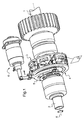
- the device of the invention is intended to selectively couple two shafts 1 and 2 rotatably mounted along the same axis X of rotation.
- the shaft 1 is secured to a pinion, while the shaft 2 is integral with a motor.
- the device of the invention essentially comprises two members, including a plate 3 and a roll holder 4 which are respectively integral in rotation with the shafts 1 and 2.
- the roll holder 4 is mounted on the shaft 2 via splines. (not visible here) which allow its axial displacement by means of a fork 5, itself moved by an actuator 6.
- the plate 3 comprises a plate 10 on which are fixed sectors 11, here six sectors, which are regularly spaced.
- Each of the sectors 11 comprises a cage 12 which is attached to the plate 10 and which has a front face 13 facing the roller holder 4 which is coplanar with the other front faces of the other sectors 11, so as to define together a flat surface P perpendicular to the axis X.
- the cages 12 have flanks which are equipped with removable plates 14, so that two removable plates 14 facing two adjacent stands 12 define between them a housing 15, the parallel faces both extend in directions parallel to a radial direction. The removable plates 14 then form the lateral faces of the housings 15.
- the roll holder 4 comprises a plate 20 associated with a central hub 21 which has six orifices regularly spaced and hollow in radial directions (the orifices are not visible).
- the plate 20 further comprises six bearings 22 arranged at the periphery of the plate 20 to be in alignment with one of the orifices of the central hub.
- Rollers 23 are mounted to turn on pins 24 (which are seen here the head exceed) each engaged in one of the orifices of the central hub 21 and in one of the bearings 22.
- pins 24 which are seen here the head exceed
- the plates 14 are made of a damping material capable of absorbing transmission jolts between the roll holder 3 and the plate 4.
- an axial abutment member is provided between the roll holder 4 and the plate 3 in order to stop these two elements axially when the rollers 23 have penetrated into the housings 15.
- the axial abutment member comprises platelets similar to the pads 14 which are arranged at the bottom of the housing 15 so that the rollers bear against these bottom plates.
- any other mode of relative axial displacement may be considered in the context of the invention, such as for example a displacement by a hydraulic pusher.
- the plate here consists of a plate on which sectors are reported, any other method of manufacture may be considered, from as the tray has a flat surface on which can come to support the rollers, and housing in which the rollers can be engaged.
Landscapes
- Engineering & Computer Science (AREA)
- General Engineering & Computer Science (AREA)
- Mechanical Engineering (AREA)
- Mechanical Operated Clutches (AREA)
- Friction Gearing (AREA)
Claims (3)
- Kupplungsvorrichtung zur Kopplung zweier Elemente, die um eine selbe Drehachse (X) drehbar gelagert sind, um einen selektiven Drehantrieb eines Elements durch das andere zu ermöglichen, wobei die Vorrichtung zwei Organe (3, 4) umfasst, die jeweils mit einem der zu koppelnden Elemente verbunden sind, wobei die Organe relativ zueinander axial zwischen einer entfernten Position, in der die Organe nicht zusammenwirken und die Elemente entkoppelt sind, und einer Eingriffsposition beweglich sind, in der die Organe miteinander zusammenwirken, um eine Drehverbindung der beiden Elemente zu gewährleisten, dadurch gekennzeichnet, dass eines der Organe eine Scheibe (3) bildet, die eine Fläche (P) hat, die senkrecht zur Drehachse ist, und in der eine Vielzahl von Aufnahmen (15) ausgebildet sind, die sich in radiale Richtungen erstrecken, wobei das andere der Elemente Rollen (23) trägt, die um radiale Achsen drehbar gelagert sind, um von dem genannten Element derart vorzustehen, dass sie jeweils in eine der Aufnahmen eingreifen können, wenn die Organe in Eingriff stehen, und mit den seitlichen Flächen (14) der Aufnahme zusammenwirken können, um eine Drehverbindung der beiden Organe sicherzustellen.
- Vorrichtung nach Anspruch 1, wobei die Scheibe eine Platte (10) umfasst, die gleichmäßig beabstandete Sektoren (11) aufnimmt, wobei die Sektoren Flanken haben, die lösbare kleine Platten (14) aufnehmen, derart, dass zwei gegenüberliegende kleine Platten, die von zwei angrenzenden Sektoren getragen werden, seitliche Flächen einer Aufnahme definieren.
- Vorrichtung nach Anspruch 2, wobei die kleinen Platten (14) aus einem Dämpfungsmaterial hergestellt sind, das dazu geeignet ist, die Übertragungsstöße zwischen den beiden Organen zu absorbieren.
Applications Claiming Priority (1)
| Application Number | Priority Date | Filing Date | Title |
|---|---|---|---|
| FR1252806A FR2988790B1 (fr) | 2012-03-28 | 2012-03-28 | Dispositif d'accouplement entre deux elements tournants |
Publications (2)
| Publication Number | Publication Date |
|---|---|
| EP2644923A1 EP2644923A1 (de) | 2013-10-02 |
| EP2644923B1 true EP2644923B1 (de) | 2015-05-06 |
Family
ID=47845882
Family Applications (1)
| Application Number | Title | Priority Date | Filing Date |
|---|---|---|---|
| EP20130159786 Active EP2644923B1 (de) | 2012-03-28 | 2013-03-18 | Kupplungvorrichtung zwischen zwei drehenden Elemente |
Country Status (4)
| Country | Link |
|---|---|
| US (1) | US9222522B2 (de) |
| EP (1) | EP2644923B1 (de) |
| CN (1) | CN103362974B (de) |
| FR (1) | FR2988790B1 (de) |
Families Citing this family (4)
| Publication number | Priority date | Publication date | Assignee | Title |
|---|---|---|---|---|
| US10151353B2 (en) * | 2014-01-23 | 2018-12-11 | GM Global Technology Operations LLC | Mechanical clutch with friction reducing interface |
| US9254747B2 (en) * | 2014-03-05 | 2016-02-09 | Shu-Chen Chan | Wheel clutch device of a rollator |
| JP2019019911A (ja) * | 2017-07-19 | 2019-02-07 | 日本精工株式会社 | クラッチ装置 |
| CN108468726B (zh) * | 2018-06-21 | 2019-12-17 | 朱东明 | 一种自动变速器 |
Family Cites Families (19)
| Publication number | Priority date | Publication date | Assignee | Title |
|---|---|---|---|---|
| US612814A (en) * | 1898-10-25 | Wagon-coupling | ||
| US900578A (en) * | 1908-06-20 | 1908-10-06 | Francis M Nichols | Clutch. |
| US1642907A (en) * | 1923-05-16 | 1927-09-20 | Sundh August | Flexible coupling |
| US1748146A (en) * | 1926-12-13 | 1930-02-25 | Ricefield Louis | Coupling |
| US1933072A (en) * | 1928-02-29 | 1933-10-31 | Ricefield Louis | Coupling |
| US2003166A (en) * | 1933-10-26 | 1935-05-28 | Zancan Ottavio | Front drive for motor cars |
| US2050910A (en) * | 1934-12-11 | 1936-08-11 | Zancan Ottavlo | Clutch |
| US2236101A (en) * | 1940-05-31 | 1941-03-25 | Detroit Power Screwdriver Comp | Torque limiting chuck |
| FR1367974A (fr) * | 1963-08-20 | 1964-07-24 | Dispositif d'accouplement élastique | |
| US3539044A (en) * | 1968-06-27 | 1970-11-10 | United Parcel Service General | Self-synchronizing clutch |
| DE2548803C2 (de) * | 1975-10-31 | 1983-09-22 | Albert Tschan KG Maschinenfabrik, 6680 Neunkirchen | Elastische Klauenkupplung |
| US4184380A (en) * | 1978-03-10 | 1980-01-22 | Rivin Evgeny I | Gears having resilient coatings |
| GB2022771B (en) * | 1978-06-08 | 1982-11-17 | Engineering Dev Ltd | Flexible couplings dampers and the like |
| FR2453314B1 (fr) * | 1979-04-04 | 1985-11-15 | Demag Ag Mannesmann | Accouplement a griffes |
| US4944196A (en) * | 1989-03-10 | 1990-07-31 | The Board Of Governors Of Wayne State University | Conjugate gear system |
| JP4779358B2 (ja) * | 2004-12-24 | 2011-09-28 | オイレス工業株式会社 | 電動式パワーステアリング装置用の軸連結機構 |
| CN2918864Y (zh) * | 2006-04-04 | 2007-07-04 | 广州市巨大传动设备有限公司 | 包容球面滚子式万向联轴器 |
| US8413781B2 (en) * | 2009-07-14 | 2013-04-09 | Patrick J. Dugas | Positive locking roller stop device |
| CN201802781U (zh) * | 2010-08-27 | 2011-04-20 | 曹磊 | 新型联轴器 |
-
2012
- 2012-03-28 FR FR1252806A patent/FR2988790B1/fr active Active
-
2013
- 2013-03-18 EP EP20130159786 patent/EP2644923B1/de active Active
- 2013-03-26 CN CN201310101139.0A patent/CN103362974B/zh active Active
- 2013-03-26 US US13/850,702 patent/US9222522B2/en active Active
Also Published As
| Publication number | Publication date |
|---|---|
| FR2988790A1 (fr) | 2013-10-04 |
| CN103362974A (zh) | 2013-10-23 |
| EP2644923A1 (de) | 2013-10-02 |
| US20130256079A1 (en) | 2013-10-03 |
| FR2988790B1 (fr) | 2014-04-11 |
| US9222522B2 (en) | 2015-12-29 |
| CN103362974B (zh) | 2016-08-03 |
Similar Documents
| Publication | Publication Date | Title |
|---|---|---|
| EP2543590B1 (de) | Elektrisches Motorisierungssystem eines Rads | |
| CA2825054C (fr) | Dispositif de freinage et d'entrainement en rotation d'une roue d'aeronef | |
| WO2002099313A1 (fr) | Dispositif de verrouillage des pignons de transmission | |
| FR2952689A1 (fr) | Differentiel a glissement limite avec dispositif de poussee dynamique | |
| EP2644923A1 (de) | Kupplungvorrichtung zwischen zwei drehenden Elemente | |
| EP0957293B1 (de) | Elektromagnetische Betätigungseinrichtung mit Gewindespindelantrieb | |
| EP2829470B1 (de) | Vorrichtung zum Drehantrieb eines Luftfahrzeugrads | |
| EP3757414A1 (de) | Vorrichtung zur drehmomentübertragung | |
| EP4185483B1 (de) | Getriebevorrichtung und rollende maschine mit einer solchen getriebevorrichtung | |
| EP1695907A1 (de) | Vorrichtung zur Verriegelung der Befestigungstruktur eines Blattes an der Nabe eines Drehflüglerrotors | |
| EP2745879A2 (de) | Übertragungsvorrichtung mit automatischer Ein- und Auskupplung | |
| EP1845181B1 (de) | Rotationsschaftmaschine, eine solche Schaftmaschine umfassende Webmaschine und Verfahren zur Steuerung einer solchen Schaftmaschine | |
| FR2940773A1 (fr) | Dispositif de transmission pour engin roulant automoteur | |
| EP3048043B1 (de) | Vorrichtung zum drehantrieb eines luftfahrzeugrads | |
| EP2612049B1 (de) | Drehmomentübertragungsvorrichtung | |
| FR2675867A1 (fr) | Dispositif de transmission a viscocoupleur controle, notamment pour vehicule automobile. | |
| EP2909509B1 (de) | Differentialvorrichtung für ein motorisiertes radfahrzeug | |
| EP2159439B1 (de) | Reibungsvorrichtung für Momentübertragung | |
| FR3136024A1 (fr) | Dispositif de couplage pour réducteur à deux rapports de vitesses | |
| EP2628888B1 (de) | Elektromechanischer rotationsantrieb für eine last mit einem momentenbegrenzer | |
| FR3096421A1 (fr) | Boîtier de transmission et engin automoteur roulant équipé d'un tel boîtier | |
| FR2888626A1 (fr) | Synchroniseur de vehicule automobile | |
| EP4544201A1 (de) | Kupplungsvorrichtung für ein untersetzungsgetriebe mit zwei übersetzungsverhältnissen | |
| FR2545177A1 (fr) | Differentiel a embrayage pour vehicules automobiles | |
| FR2760058A1 (fr) | Dispositif d'embrayage centrifuge, notamment pour vehicule leger |
Legal Events
| Date | Code | Title | Description |
|---|---|---|---|
| PUAI | Public reference made under article 153(3) epc to a published international application that has entered the european phase |
Free format text: ORIGINAL CODE: 0009012 |
|
| AK | Designated contracting states |
Kind code of ref document: A1 Designated state(s): AL AT BE BG CH CY CZ DE DK EE ES FI FR GB GR HR HU IE IS IT LI LT LU LV MC MK MT NL NO PL PT RO RS SE SI SK SM TR |
|
| AX | Request for extension of the european patent |
Extension state: BA ME |
|
| 17P | Request for examination filed |
Effective date: 20140328 |
|
| RBV | Designated contracting states (corrected) |
Designated state(s): AL AT BE BG CH CY CZ DE DK EE ES FI FR GB GR HR HU IE IS IT LI LT LU LV MC MK MT NL NO PL PT RO RS SE SI SK SM TR |
|
| GRAP | Despatch of communication of intention to grant a patent |
Free format text: ORIGINAL CODE: EPIDOSNIGR1 |
|
| INTG | Intention to grant announced |
Effective date: 20141017 |
|
| GRAS | Grant fee paid |
Free format text: ORIGINAL CODE: EPIDOSNIGR3 |
|
| GRAA | (expected) grant |
Free format text: ORIGINAL CODE: 0009210 |
|
| AK | Designated contracting states |
Kind code of ref document: B1 Designated state(s): AL AT BE BG CH CY CZ DE DK EE ES FI FR GB GR HR HU IE IS IT LI LT LU LV MC MK MT NL NO PL PT RO RS SE SI SK SM TR |
|
| REG | Reference to a national code |
Ref country code: GB Ref legal event code: FG4D Free format text: NOT ENGLISH |
|
| REG | Reference to a national code |
Ref country code: CH Ref legal event code: EP |
|
| REG | Reference to a national code |
Ref country code: IE Ref legal event code: FG4D Free format text: LANGUAGE OF EP DOCUMENT: FRENCH |
|
| REG | Reference to a national code |
Ref country code: AT Ref legal event code: REF Ref document number: 725920 Country of ref document: AT Kind code of ref document: T Effective date: 20150615 |
|
| REG | Reference to a national code |
Ref country code: DE Ref legal event code: R096 Ref document number: 602013001661 Country of ref document: DE Effective date: 20150625 |
|
| REG | Reference to a national code |
Ref country code: AT Ref legal event code: MK05 Ref document number: 725920 Country of ref document: AT Kind code of ref document: T Effective date: 20150506 |
|
| REG | Reference to a national code |
Ref country code: NL Ref legal event code: MP Effective date: 20150506 |
|
| REG | Reference to a national code |
Ref country code: LT Ref legal event code: MG4D |
|
| PG25 | Lapsed in a contracting state [announced via postgrant information from national office to epo] |
Ref country code: FI Free format text: LAPSE BECAUSE OF FAILURE TO SUBMIT A TRANSLATION OF THE DESCRIPTION OR TO PAY THE FEE WITHIN THE PRESCRIBED TIME-LIMIT Effective date: 20150506 Ref country code: HR Free format text: LAPSE BECAUSE OF FAILURE TO SUBMIT A TRANSLATION OF THE DESCRIPTION OR TO PAY THE FEE WITHIN THE PRESCRIBED TIME-LIMIT Effective date: 20150506 Ref country code: NO Free format text: LAPSE BECAUSE OF FAILURE TO SUBMIT A TRANSLATION OF THE DESCRIPTION OR TO PAY THE FEE WITHIN THE PRESCRIBED TIME-LIMIT Effective date: 20150806 Ref country code: ES Free format text: LAPSE BECAUSE OF FAILURE TO SUBMIT A TRANSLATION OF THE DESCRIPTION OR TO PAY THE FEE WITHIN THE PRESCRIBED TIME-LIMIT Effective date: 20150506 Ref country code: PT Free format text: LAPSE BECAUSE OF FAILURE TO SUBMIT A TRANSLATION OF THE DESCRIPTION OR TO PAY THE FEE WITHIN THE PRESCRIBED TIME-LIMIT Effective date: 20150907 Ref country code: LT Free format text: LAPSE BECAUSE OF FAILURE TO SUBMIT A TRANSLATION OF THE DESCRIPTION OR TO PAY THE FEE WITHIN THE PRESCRIBED TIME-LIMIT Effective date: 20150506 |
|
| PG25 | Lapsed in a contracting state [announced via postgrant information from national office to epo] |
Ref country code: LV Free format text: LAPSE BECAUSE OF FAILURE TO SUBMIT A TRANSLATION OF THE DESCRIPTION OR TO PAY THE FEE WITHIN THE PRESCRIBED TIME-LIMIT Effective date: 20150506 Ref country code: GR Free format text: LAPSE BECAUSE OF FAILURE TO SUBMIT A TRANSLATION OF THE DESCRIPTION OR TO PAY THE FEE WITHIN THE PRESCRIBED TIME-LIMIT Effective date: 20150807 Ref country code: AT Free format text: LAPSE BECAUSE OF FAILURE TO SUBMIT A TRANSLATION OF THE DESCRIPTION OR TO PAY THE FEE WITHIN THE PRESCRIBED TIME-LIMIT Effective date: 20150506 Ref country code: BG Free format text: LAPSE BECAUSE OF FAILURE TO SUBMIT A TRANSLATION OF THE DESCRIPTION OR TO PAY THE FEE WITHIN THE PRESCRIBED TIME-LIMIT Effective date: 20150806 Ref country code: RS Free format text: LAPSE BECAUSE OF FAILURE TO SUBMIT A TRANSLATION OF THE DESCRIPTION OR TO PAY THE FEE WITHIN THE PRESCRIBED TIME-LIMIT Effective date: 20150506 Ref country code: IS Free format text: LAPSE BECAUSE OF FAILURE TO SUBMIT A TRANSLATION OF THE DESCRIPTION OR TO PAY THE FEE WITHIN THE PRESCRIBED TIME-LIMIT Effective date: 20150906 |
|
| PG25 | Lapsed in a contracting state [announced via postgrant information from national office to epo] |
Ref country code: EE Free format text: LAPSE BECAUSE OF FAILURE TO SUBMIT A TRANSLATION OF THE DESCRIPTION OR TO PAY THE FEE WITHIN THE PRESCRIBED TIME-LIMIT Effective date: 20150506 Ref country code: DK Free format text: LAPSE BECAUSE OF FAILURE TO SUBMIT A TRANSLATION OF THE DESCRIPTION OR TO PAY THE FEE WITHIN THE PRESCRIBED TIME-LIMIT Effective date: 20150506 |
|
| REG | Reference to a national code |
Ref country code: DE Ref legal event code: R097 Ref document number: 602013001661 Country of ref document: DE |
|
| PG25 | Lapsed in a contracting state [announced via postgrant information from national office to epo] |
Ref country code: PL Free format text: LAPSE BECAUSE OF FAILURE TO SUBMIT A TRANSLATION OF THE DESCRIPTION OR TO PAY THE FEE WITHIN THE PRESCRIBED TIME-LIMIT Effective date: 20150506 Ref country code: RO Free format text: LAPSE BECAUSE OF NON-PAYMENT OF DUE FEES Effective date: 20150506 Ref country code: SK Free format text: LAPSE BECAUSE OF FAILURE TO SUBMIT A TRANSLATION OF THE DESCRIPTION OR TO PAY THE FEE WITHIN THE PRESCRIBED TIME-LIMIT Effective date: 20150506 Ref country code: CZ Free format text: LAPSE BECAUSE OF FAILURE TO SUBMIT A TRANSLATION OF THE DESCRIPTION OR TO PAY THE FEE WITHIN THE PRESCRIBED TIME-LIMIT Effective date: 20150506 |
|
| PLBE | No opposition filed within time limit |
Free format text: ORIGINAL CODE: 0009261 |
|
| STAA | Information on the status of an ep patent application or granted ep patent |
Free format text: STATUS: NO OPPOSITION FILED WITHIN TIME LIMIT |
|
| REG | Reference to a national code |
Ref country code: FR Ref legal event code: PLFP Year of fee payment: 4 |
|
| 26N | No opposition filed |
Effective date: 20160209 |
|
| PG25 | Lapsed in a contracting state [announced via postgrant information from national office to epo] |
Ref country code: IT Free format text: LAPSE BECAUSE OF FAILURE TO SUBMIT A TRANSLATION OF THE DESCRIPTION OR TO PAY THE FEE WITHIN THE PRESCRIBED TIME-LIMIT Effective date: 20150506 |
|
| PG25 | Lapsed in a contracting state [announced via postgrant information from national office to epo] |
Ref country code: SI Free format text: LAPSE BECAUSE OF FAILURE TO SUBMIT A TRANSLATION OF THE DESCRIPTION OR TO PAY THE FEE WITHIN THE PRESCRIBED TIME-LIMIT Effective date: 20150506 |
|
| PG25 | Lapsed in a contracting state [announced via postgrant information from national office to epo] |
Ref country code: BE Free format text: LAPSE BECAUSE OF NON-PAYMENT OF DUE FEES Effective date: 20160331 |
|
| PG25 | Lapsed in a contracting state [announced via postgrant information from national office to epo] |
Ref country code: MC Free format text: LAPSE BECAUSE OF FAILURE TO SUBMIT A TRANSLATION OF THE DESCRIPTION OR TO PAY THE FEE WITHIN THE PRESCRIBED TIME-LIMIT Effective date: 20150506 Ref country code: LU Free format text: LAPSE BECAUSE OF FAILURE TO SUBMIT A TRANSLATION OF THE DESCRIPTION OR TO PAY THE FEE WITHIN THE PRESCRIBED TIME-LIMIT Effective date: 20160318 |
|
| REG | Reference to a national code |
Ref country code: CH Ref legal event code: PL |
|
| REG | Reference to a national code |
Ref country code: IE Ref legal event code: MM4A |
|
| PG25 | Lapsed in a contracting state [announced via postgrant information from national office to epo] |
Ref country code: IE Free format text: LAPSE BECAUSE OF NON-PAYMENT OF DUE FEES Effective date: 20160318 Ref country code: CH Free format text: LAPSE BECAUSE OF NON-PAYMENT OF DUE FEES Effective date: 20160331 Ref country code: LI Free format text: LAPSE BECAUSE OF NON-PAYMENT OF DUE FEES Effective date: 20160331 |
|
| REG | Reference to a national code |
Ref country code: FR Ref legal event code: PLFP Year of fee payment: 5 |
|
| REG | Reference to a national code |
Ref country code: FR Ref legal event code: CD Owner name: MESSIER-BUGATTI-DOWTY, FR Effective date: 20170518 |
|
| PG25 | Lapsed in a contracting state [announced via postgrant information from national office to epo] |
Ref country code: SE Free format text: LAPSE BECAUSE OF FAILURE TO SUBMIT A TRANSLATION OF THE DESCRIPTION OR TO PAY THE FEE WITHIN THE PRESCRIBED TIME-LIMIT Effective date: 20150506 Ref country code: NL Free format text: LAPSE BECAUSE OF FAILURE TO SUBMIT A TRANSLATION OF THE DESCRIPTION OR TO PAY THE FEE WITHIN THE PRESCRIBED TIME-LIMIT Effective date: 20150506 |
|
| PG25 | Lapsed in a contracting state [announced via postgrant information from national office to epo] |
Ref country code: MT Free format text: LAPSE BECAUSE OF FAILURE TO SUBMIT A TRANSLATION OF THE DESCRIPTION OR TO PAY THE FEE WITHIN THE PRESCRIBED TIME-LIMIT Effective date: 20150506 |
|
| REG | Reference to a national code |
Ref country code: FR Ref legal event code: PLFP Year of fee payment: 6 |
|
| PG25 | Lapsed in a contracting state [announced via postgrant information from national office to epo] |
Ref country code: HU Free format text: LAPSE BECAUSE OF FAILURE TO SUBMIT A TRANSLATION OF THE DESCRIPTION OR TO PAY THE FEE WITHIN THE PRESCRIBED TIME-LIMIT; INVALID AB INITIO Effective date: 20130318 Ref country code: SM Free format text: LAPSE BECAUSE OF FAILURE TO SUBMIT A TRANSLATION OF THE DESCRIPTION OR TO PAY THE FEE WITHIN THE PRESCRIBED TIME-LIMIT Effective date: 20150506 Ref country code: CY Free format text: LAPSE BECAUSE OF FAILURE TO SUBMIT A TRANSLATION OF THE DESCRIPTION OR TO PAY THE FEE WITHIN THE PRESCRIBED TIME-LIMIT Effective date: 20150506 |
|
| PG25 | Lapsed in a contracting state [announced via postgrant information from national office to epo] |
Ref country code: TR Free format text: LAPSE BECAUSE OF FAILURE TO SUBMIT A TRANSLATION OF THE DESCRIPTION OR TO PAY THE FEE WITHIN THE PRESCRIBED TIME-LIMIT Effective date: 20150506 Ref country code: MK Free format text: LAPSE BECAUSE OF FAILURE TO SUBMIT A TRANSLATION OF THE DESCRIPTION OR TO PAY THE FEE WITHIN THE PRESCRIBED TIME-LIMIT Effective date: 20150506 |
|
| PG25 | Lapsed in a contracting state [announced via postgrant information from national office to epo] |
Ref country code: AL Free format text: LAPSE BECAUSE OF FAILURE TO SUBMIT A TRANSLATION OF THE DESCRIPTION OR TO PAY THE FEE WITHIN THE PRESCRIBED TIME-LIMIT Effective date: 20150506 |
|
| PGFP | Annual fee paid to national office [announced via postgrant information from national office to epo] |
Ref country code: GB Payment date: 20260317 Year of fee payment: 14 |
|
| PGFP | Annual fee paid to national office [announced via postgrant information from national office to epo] |
Ref country code: DE Payment date: 20260320 Year of fee payment: 14 |
|
| PGFP | Annual fee paid to national office [announced via postgrant information from national office to epo] |
Ref country code: FR Payment date: 20260318 Year of fee payment: 14 |